TFT14402560 3 E(5.98D)v1.0(1) (PDF)
File information
Title: TFT14402560-3-E_5.98D_v1.0.doc
Author: huangsuling
This PDF 1.4 document has been generated by pdfFactory Pro www.fineprint.com.cn / pdfFactory Pro 2.25 (Windows XP Chinese), and has been sent on pdf-archive.com on 24/05/2016 at 12:29, from IP address 91.233.x.x.
The current document download page has been viewed 1465 times.
File size: 851.77 KB (28 pages).
Privacy: public file


File preview
SPECIFICATION
产品说明书
Revision: 1.0
版本: 1.0
Part Number:TFT14402560-3-E
This module uses ROHS material
模块用环保材料
P.1
Version: 1.0
April 11, 2014
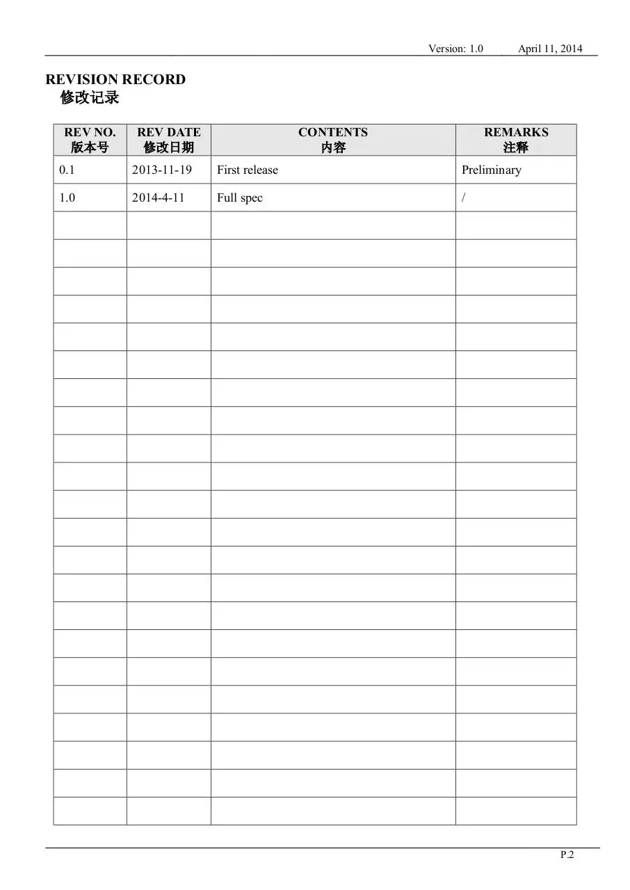
REVISION RECORD
修改记录
REV NO.
版本号
REV DATE
修改日期
CONTENTS
内容
REMARKS
注释
0.1
2013-11-19
First release
Preliminary
1.0
2014-4-11
Full spec
/
P.2
Version: 1.0
April 11, 2014
CONTENTS 内容
n GENERAL INFORMATION
主要特征描述
n EXTERNAL DIMENSIONS
外形尺寸
n ABSOLUTE MAXIMUM RATINGS
极限参数
n ELECTRICAL CHARACTERISTICS
模块电气特性
n BACKLIGHT CHARACTERISTICS
背光电气特性
n ELECTRO-OPTICAL CHARACTERISTICS
光电参数
n INTERFACE DESCRIPTION
接口定义描述
n REFERENCE APPLICATION CIRCUIT
参考应用电路
n RELIABILITY TEST CONDITIONS
可靠性试验条件
n INSPECTION CRITERION
检查标准
n PRECAUTIONS FOR USING LCD MODULES
使用注意事项
n PACKING SPECIFICATION
包装规格书
n PRIOR CONSULT MATTER
提前商议事项
n FACTORY CONTACT INFORMATION
工厂联系信息
WRITTEN BY
制作
CHECKED BY
检查
APPROVED BY
核准
HUANG SU LING
ZHANG SHUI
ZHANG SHU HANG
P.3
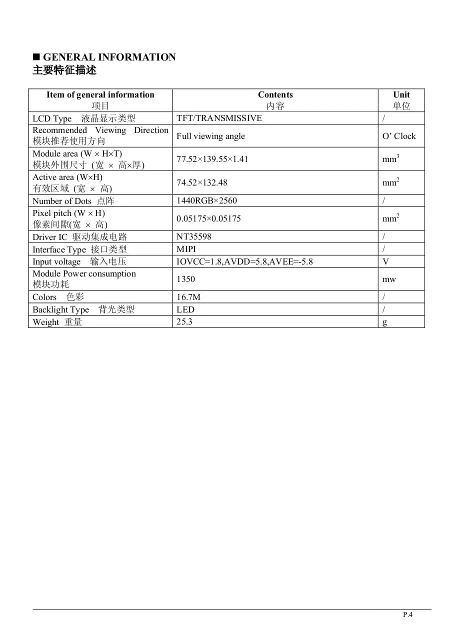
n GENERAL INFORMATION
主要特征描述
Item of general information
项目
LCD Type 液晶显示类型
Recommended Viewing Direction
模块推荐使用方向
Module area (W ´ H´T)
模块外围尺寸 (宽 ´ 高´厚)
Active area (W´H)
有效区域 (宽 ´ 高)
Number of Dots 点阵
Pixel pitch (W ´ H)
像素间隙(宽 ´ 高)
Driver IC 驱动集成电路
Interface Type 接口类型
Input voltage 输入电压
Module Power consumption
模块功耗
Colors 色彩
Backlight Type 背光类型
Weight 重量
Contents
内容
TFT/TRANSMISSIVE
Unit
单位
/
Full viewing angle
O’ Clock
77.52×139.55×1.41
mm3
74.52×132.48
mm2
1440RGB×2560
/
0.05175×0.05175
mm2
NT35598
MIPI
IOVCC=1.8,AVDD=5.8,AVEE=-5.8
/
/
V
1350
mw
16.7M
LED
25.3
/
/
g
P.4
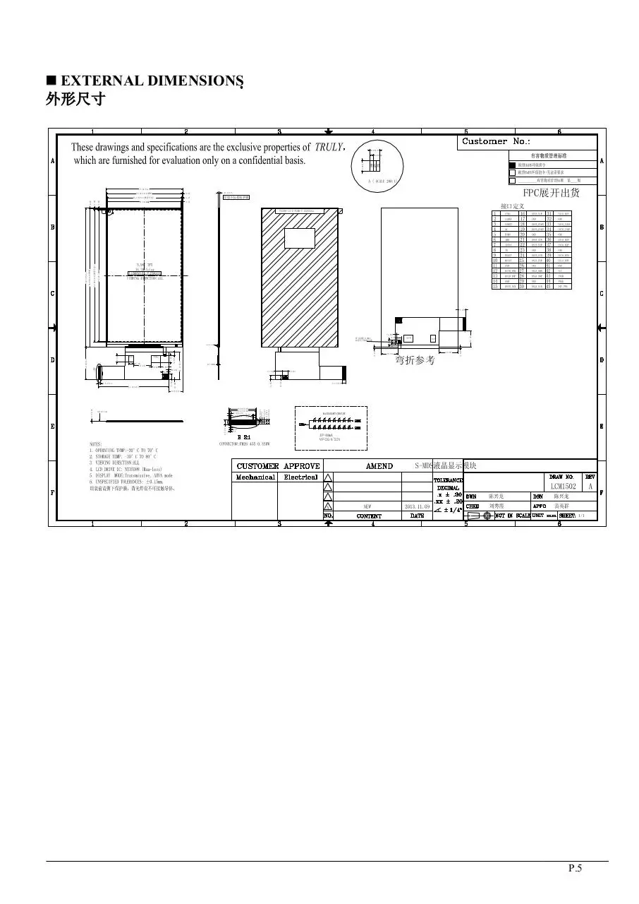
n EXTERNAL DIMENSIONS
外形尺寸
0.05175
0.05175
0.01725
FPC展开出货
(0.6)
(1.2)
74.52(AA)
(1.5)
(1.47)
(1.18)
(0.47)
77.52±0.2
76.32±0.2( TFT)
75.12±0.2(推荐开窗)
1.41±0.15
厚度不包括保护膜
接口定义
132.48( AA)
139.55±0.2
138.88±0.2(TFT)
133.08±0.2(推荐开窗)
TS598-13-C-P2S8-T XXXXXXa
(7.85)
(4.8)
(0.96)
(5)
弯折参考
(1.02)
(19.07)
(16.65)
(5.75)
(7.56)
(4.85)
71.57±0.2
0.7(MAX)
(5.56)
(0.39)
(6)
2.5±0.3
4
(1.22)
(8.66)
(4.54)
(2.97)
(7.07)
(9.62)
27.77±0.2
(6.74)
32.9±0.3
(5.11)
(17.74)
(16.32)
(1.85)
焊盘高度0.3MAX
焊盘不可接触导体
PROTECT GLUE
3.5±0.3
0.6±0.02
+0.04
0.3±0.020.3-0.03
0.3±0.1
1±0.1
1.1±0.1
2.1±0.1
2.25±0.1
13.8±0.07
13.2±0.03
CONTECT SIDE
2.5±0.3
0.2±0.03
13.8±0.3
0.1
0.2
0.2
IF=40mA
VF=20.6~25V
1/1
P.5
n ABSOLUTE MAXIMUM RATINGS
极限参数
Parameter of absolute
Symbol
Min
Max
Unit
maximum ratings 参数
符号
最小值
最大值
单位
Analog power supply
AVDD
-0.3
6.6
V
模拟电压
AVEE
-6.6
0.3
V
I/O power supply
IOVCC
-0.3
5.5
V
接口电压
Input voltage
VIN
-0.3
4
V
输入电压
Operating temperature
Top
-20
70
°C
操作温度
Storage temperature
TST
-30
80
°C
储存温度
Humidity
RH
90%(Max60 °C)
RH
湿度
Note: Absolute maximum ratings means the product can withstand short-term, NOT more than 120 hours.
If the product is a long time to withstand these conditions, the life time would be shorter.
备注:极限条件仅指产品能短暂承受的范围,不可超过 120 小时。如果产品长时间在极限条件,将有
损产品的使用寿命。
n ELECTRICAL CHARACTERISTICS
模块电气特性
DC CHARACTERISTICS
直流特性
Parameter of DC
characteristics 参数
Analog power supply
模拟电压
I/O power supply
接口电压
Input Current
输入电流
Input voltage 'H' level
输入高电平
Input voltage 'L' level
输入低电平
Output voltage 'H' level
输出高电平
Output voltage 'L' level
输出低电平
Symbol
符号
AVDD
AVEE
Min
最小值
4.6
-6.0
Typ
典型值
5.8
-5.8
Max
最大值
6.0
-4.6
Unit
单位
V
V
IOVCC
1.65
1.8
3.6
V
IIOVCC
IAVDD
IAVEE
-
55
15
16
66
22.5
19.5
mA
VIH
0.7IOVCC
-
IOVCC
V
VIL
GND
-
0.3IOVCC V
VOH
0.8IOVCC
-
IOVCC
VOL
GND
-
0.2IOVCC V
V
P.6
n BACKLIGHT CHARACTERISTICS
背光电气特性
Item of backlight
characteristics 项目
Forward voltage正向电压
Symbol
Vf
Min.
20.6
Typ.
Max.
22.8
25.0
2*8
Number of LED 灯数
Connection mode 连 接 类
P/S
Parallel/Serial 型
Using condition: constant current driving method If=40mA(+/-10%).
使用条件:恒流的驱动方式是 If=40mA(+/-10%).
Unit
Condition
Piece
If=40mA;Ta=25
℃
-
-
-
V
n ELECTRO-OPTICAL CHARACTERISTICS
光电参数
Item of
electro-optical
characteristics
项目
Response time
响应时间
Contrast ratio
对比度
Luminance
uniformity
均匀度
Surface
Luminance
表面亮度
Symbol
符号
Condition 条件
Tr+ Tf
Cr
d WHITE
θ=0°
Æ=0°
Ta=25℃
Lv
Min
Typ
Max
最小值 典型值 最大值
Unit
单位
Remark
注释
Note
备
注
-
40
60
ms
FIG 1.
4
300
900
-
---
FIG 2.
1
80
-
-
%
FIG 2.
3
280
350
-
cd/m2 FIG 2.
2
Viewing angle
range
q
视角范围
Æ = 90°
Æ = 270°
Æ = 0°
Æ = 180°
70
70
70
70
80
80
80
80
-
deg
deg
deg
deg
FIG 3.
FIG 3
FIG 3
FIG 3
6
NTSC ratio
色彩饱和度
-
-
65
-
%
-
-
θ=0°
Æ=0°
Ta=25℃
0.5798
0.2867
0.2471
0.5256
0.0992
0.0073
0.2266
0.2333
0.6298
0.3367
0.2971
0.5756
0.1492
0.0573
0.2866
0.2933
0.6798
0.3867
0.3471
0.6256
0.1992
0.1073
0.3466
0.3533
-
FIG 2.
5
-
Red x
Red y
Green x
CIE (x, y)
Green y
chromaticity
Blue x
CIE 色度坐标
Blue y
White x
White y
Note1.
Contrast Ratio(CR) is defined mathematically by the following formula. For more
information see FIG 2.:
Contrast Ratio(CR) = Average Surface Luminance with all white pixels (P1, P2, ……)
Average Surface Luminance with all black pixels (P1, P2, ……)
P.7
备注1. 对比度是由以下公式计算所得。详见FIG 2.。
对比度= 显示白色画面时平均表面亮度(P 1,P2, ……) /显示黑色画面时平均表面亮度(P
1,P2, ……)
Note2.
Surface luminance is the LCD surface luminance with all white pixels.
information see FIG 2.
Lv = Average Surface Luminance with all white pixels (P1, P2, …… )
备注2. 表面亮度是在显示白色画面时,测试的亮度值,详见FIG 2.。
Lv =平均的表面亮度(P1, P2, …… )
For more
Note3.
The uniformity in surface luminance (d WHITE) is determined by measuring luminance at
each test position, and then dividing the maximum luminance of all white pixels by minimum
luminance of all white pixels. For more information see FIG 2.
d WHITE =
Minimum Surface Luminance with all white pixels (P1, P2, ……)
Maximum Surface Luminance with all white pixels (P1, P2, ……)
备注3. 均匀度是在显示白色画面时,测试P1到P9的亮度,然后再用9个点亮度的最小值除
以最大值。详见FIG 2.。
均匀度 =白色画面下表面亮度最小值 (P1, P2, ……) /白色画面下表面高度最大值 (P1,
P2, ……)
Note4.
Response time is the time required for the display to transition from White to black(Rise
Time, Tr) and from black to white(Decay Time, Tf). For additional information see FIG 1..
备注4. 响应时间是 Tr(上升时间)与Tf(下降时间)的和; Tr 指显示白色画面转为显
示黑色画面需要时间, Tf 指显示黑色画面转为显示白色画面需要时间。详见FIG 1.。
Note5.
CIE(x, y) chromaticity is the Center point value. For more information see FIG 2.
备注5. 选择中心点 分别测试x,y值。详见FIG 2.。
Note6.
Viewing angle is the angle at which the contrast ratio is greater than a specific value. For
TFT module, the specific value of conrast ratio is 10; For monochrome and color stn module, the
specific value of conrast ratio is 2.The angles are determined for the horizontal or x axis and the
vertical or y axis with respect to the z axis which is normal to the LCD surface. For more
information see FIG 3.
备注6. 视角
指对比度大于等于一个特定值时的可视范围,对TFT屏,对比度特定值
为10,对黑白屏,CSTN屏,对比度特定值为2。视角由横轴(x轴),竖轴(y轴)同Z轴
(垂直于LCD表面)之间的夹角来定义。详见FIG 3.。
Note7.
For Viewing angle and response time testing, the testing data is base on Autronic-Melchers’s
ConoScope. Series Instruments. For contrast ratio, Surface Luminance, Luminance uniformity and
CIE,the testing data is base on CS-2000 photo detector.
备注7. 视角和响应时间, 测试数据基于Autronic-Melchers’s ConoScope.系列。而
对比度,表面亮度,均匀度,CIE坐标,测试数据基于CS-2000 photo detector。
Note8.
For TN type TFT transmissive module, Gray scale reverse occurs in the direction of
panel viewing angle
备注8. TN型TFT全透产品,在视角方向会发生灰度反转。
P.8
FIG.1.
The definition of Response Time
FIG.2.
Measuring method for Contrast ratio, surface luminance, Luminance uniformity,CIE
(x, y) chromaticity
Fig2 Note1 For TFT Module
Test point:9 points( as 9 Points diagram )
A : H/6 (if AA size<4.0inch);
B : V/6 (if AA size<4.0inch);
H,V : Active Area(AA) size
Measurement instrument: CS-2000; Light spot size Æ=5mm, 350mm distance from the LCD
surface to detector lens.
Fig2 Note2 For non-TFT Module and Dot-Matrix type Module
2.1 If the minimum side size is bigger than 20 mm,the testing method is the same as TFT module.
2.2 If the minimum side size is less than 20 mm, then testing 5 point datas (as 5 Points diagram),
Both A and B are 5 mm.
2.3 Measurement instrument: CS-2000 is priority selected to measure.
Light spot size Æ=5mm, 350mm distance from the LCD surface to detector lens.
2.4 Measurement instrument : ConoScope will be selelected to measure If CS-2000 cannot meet
the measurement requirement.
Light spot size Æ=0.2-2.0mm. About 2-3mm distance from the LCD surface to detector lens,
but suggest to confirm the best distance on focusing the picture to be clearest when actually
measuring.
Fig2 Note3 For non-TFT Module and non-Dot-Matrix type Module
The test point is defined by the fact size and shape of module,but the center point and four edges
should be selected.
3.1 Measurement instrument: CS-2000 is priority selected to measure..
P.9
Download TFT14402560-3-E(5.98D)v1.0(1)
TFT14402560-3-E(5.98D)v1.0(1).pdf (PDF, 851.77 KB)
Download PDF
Share this file on social networks
Link to this page
Permanent link
Use the permanent link to the download page to share your document on Facebook, Twitter, LinkedIn, or directly with a contact by e-Mail, Messenger, Whatsapp, Line..
Short link
Use the short link to share your document on Twitter or by text message (SMS)
HTML Code
Copy the following HTML code to share your document on a Website or Blog
QR Code to this page

This file has been shared publicly by a user of PDF Archive.
Document ID: 0000376163.