regulator (PDF)
File information
Title: Microsoft Word - regulator.docx
Author: Sumedhe
This PDF 1.3 document has been generated by PrimoPDF http://www.primopdf.com / Nitro PDF PrimoPDF, and has been sent on pdf-archive.com on 18/02/2011 at 02:10, from IP address 74.240.x.x.
The current document download page has been viewed 1710 times.
File size: 212.96 KB (5 pages).
Privacy: public file

File preview
MAXSUM
REGULATOR PCB VERSION 1.1
MAXSUM
PCB Specification:
Material
Number of Copper Layers
Finish
Silk Screen
Board Thickness
Copper Thickness
Solder Mask
Board Size
FR-4 Fiber Glass
1
HAL (no lead free)
Yes – White
1.6mm
1 oz
Yes (Green)
9.65 cm X 6.70 cm
Features:
•
•
•
•
•
•
•
•
•
Can be used as a single polarity power supply or dual polarity power supply.
Can be used as a fixed voltage supply (using 78xx and 779xx series) or adjustable voltage power
supply.
Can be used as AC to DC regulator or DC to DC (Read Tips 3) regulator.
Enough space to mount big heat sink for high current usage.
Many circuit protection features.
o Short circuit protection (via optional dual fuses)
o Protection Diodes to protect regulator chips from capacitor discharges.
Additional holes to mount few sizes of capacitors and variable resistors.
Compact design yet enough space to mount parts nicely.
Improve ripple rejection (refer the data sheet for LM31
LM317 and circuit diagram)
Dual LED indicators to show status of the system.
Circuit Diagram:
2
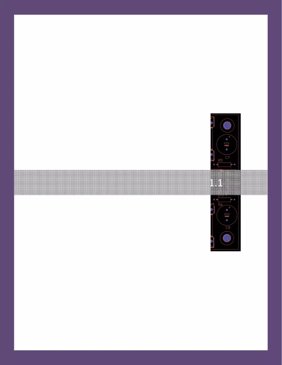
The actual circuit diagram used to produce the PCB is given in the above figure. The parts that should
put in to the PCB will depend on the outcome user needs. For example user can use jumpers instead of
fuses if he does not want over current protection (not recommended). Please refer to “Tips” part of this
document for more information.
Part List:
Part
C1, C2
C3, C4, C9, C10
C5, C6
C7, C8
D1, D2, D3, D4
D5, D6, D7, D8
F1, F2
IC1
IC2
IC3
LED1, LED2
R1, R2
R3, R4
R5, R6
U$1
U$2
Heat Sinks
Value
4700uF
0.1uF
10uF
1000uF
HER305
1N4002
Fuse
LM317
78xx
79xx / LM337
LED
See Tips 1
See Tips 1
See Tips 2
AC/DC Input
DC Out
-
Package
EB20D
C025_050-025X075
E2,5-5
E5-10,5
DO201-15
DO41-10
HK20Q
TO220
T0220
TO220
LED5MM
RTRIMT93YA
Resistor Flat
Resistor Flat
3POL350 (3mm pitch)
3POL350 (3mm pitch)
Usage:
The PCB can use to make single/dual and fix/adjustable power supply. However the user should put
appropriate parts to do that.
You can give AC or DC input to get regulated DC output. If you like to use this as DC to DC regulator, then
make sure to reed Tips number 3.
3
Fix Voltage Dual Power Supply Regulator:
Do not insert parts in side red regions
Insert a Jumper here!
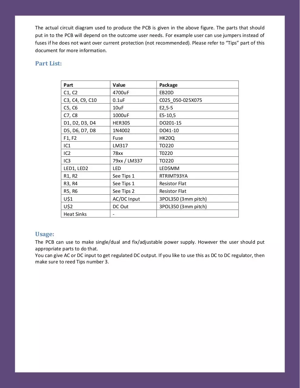
To make fix voltage dual power supply please insert the all the items in the part list except R1, R2, R3,
R4, D5, D6, D7, D8, C5 ,C6 and IC1 that are shown in a red boxes. IC2 should be 78xx while IC3 should be
79xx.. Last two digits represent the fix voltage you want. For example, use 7805 and 7905 for ±5V
regulator.. Do not put anything for IC2.
It is very important of inserting a jumper (a wire) instead of C6. Please see the figure.
Adjustable Dual Voltage Regulator:
To make an adjustable dual voltage regulator, you should insert all the items except IC2. IC1 should be
LM317 while IC2 should be LM337.
4
Tips
1. You need to calculate R1, R2, R3 and R4 for according to the output voltage you need. You can
take help from http://www.whatcircuits.com/lm317-calculator-v2/ .
Positive voltage output with respective to R1 and R3 is given by
Vout+ = 1.25(1+R1/R3)
Similarly negative voltage output with respective to R2 and R4 is given by
Vout- = -1.25(1+R2/R4)
For example if you want to build +/-15V adjustable regulator and if we want to use 10KOhm
potentiometer for R1, then we can find R3 just by using the equation.
R3 =
R1
V0ut +
− 1
1.25
=
10 KOhm
= 0.909 KOhm
15
− 1
1.25
However, it may be difficult to find 0.909Kohm resistor. So you can use some close value
available, 820Ohms resistor instead. Using
2. R5 and R6 are current limiting resistors for LED. To calculate R5 and R6, you can get some help
from http://www.hebeiltd.com.cn/?p=zz.led.resistor.calculator
If you are using fix output regulator, it will be easy to calculate the resistance using this
calculator (in the link) .However if you are building variable regulator, since output voltage is
changing as you change the potentiometers, it is vise to calculate resistor when you have
maximum possible output. However, note that as you decrease the voltage LED will become
dimmer or off.
3. If you would like to use this as DC to DC regulator, then you can omit D1 , D2, D3 and D4 diodes.
Now make sure to insert jumpers instead of D2 and D4 diodes. DO NOT put jumpers to D1 and
D4 spots.
Note: Even you use this as DC to DC keeping these diodes will save the circuit from polarity
changes.
Please contact us via eBay mail if you have any additional questions or if any
of this document are not clear. We are happy to help you as much as we can.
Our eBay user ID is “maxsum”
5
Download regulator
regulator.pdf (PDF, 212.96 KB)
Download PDF
Share this file on social networks
Link to this page
Permanent link
Use the permanent link to the download page to share your document on Facebook, Twitter, LinkedIn, or directly with a contact by e-Mail, Messenger, Whatsapp, Line..
Short link
Use the short link to share your document on Twitter or by text message (SMS)
HTML Code
Copy the following HTML code to share your document on a Website or Blog
QR Code to this page

This file has been shared publicly by a user of PDF Archive.
Document ID: 0000028632.