.MAY
15, 19°^
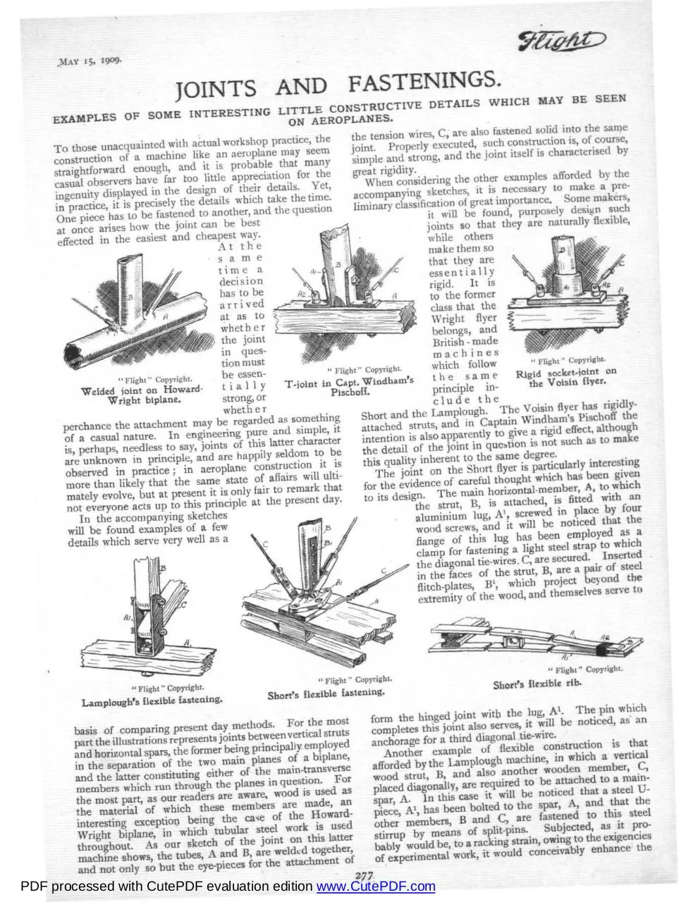
JOINTS AND FASTENINGS.
EXAMPLES
T o those
unalCquainted
with actual workshop practice, the
of a machine like an aeroplane may ijeem
•
• „- Q a r e a i s o fastened solid into the same
*ejensu>
^
^ c o n s t m c t i is> of course
joint. ^ j™9^^
a n dt h e j o i n t i t s e l f 1S characterised by
the other examples afforded by the
One P i ce'has to be fastened to another, and the question
at once arises how the joint can be best
effected in the easiest and cheapest way.
J\ t t n e
s a m e
time a
decision
has to be
arrived
at as to
whether
the joint
in question must
" Flight" Copyright.
be essen"Flight" Copyright.
T-joint in Capt. Windham's
t i a11 y
Welded joint on HowardPiscboff.
Wright biplane.
strong, or
sg,
01 a casual nature. Ii- - - D
is, perhaps, needless to say, joints of - " - " . - ;
t
b
are unknown in principle, and are happly se dom to be
observed in practice ; in aeroplane oon^uctoon, rt ^s
more than likely that the same state of affairs^ U um
mately evolve, but at present it is only fa. to remark tot
not everyone acts up to this principle at the present day.
In the accompanying sketches
will be found examples of a few
details which serve very well as a
it Will Dc luuiiu,
puii^«>-v
c-
joints so that they are naturally flexible,
while others
make them so
that they are
essentially
rigid. It is
to the former
class that the
Wright flyer
belongs, and
British - made
machines
" Flight" Copyright.
which follow
Rigid socket'joint on
the same
the Voisin flyer.
principle include the
such as
"
extremity of the'wood, and themselves serve to
" Flight" Copyright.
" Flight" Copyright.
" Flight" Copyright.
Lamplough's flexible fastening.
Short's flexible fastening.
V
Short's flexible rib-
anchorage for a . h M diagonal
m
for the attachment
277
and not with
only so
but the evaluation edition www.CutePDF.com
PDF processed
CutePDF
�
MAY 15,
1909.
Another little device initially designed for a special
purpose, but which might conceivably have extended
utility, is the flexible rib on the Short flyer. It is a feature
of the Short construction that the surfaces of their main
planes are as rigid and exact in contour as they can
possibly make them. On the other hand, however, it
will be recollected that their machine embodies rearward
extensions of the main-plane in the form of " lips," which
can be flexed on either side of the neutral stream line for
the purposes of righting and steering. One of the
accompanying sketches shows how this flexibility is
obtained. The top and bottom laths, A and A1, which
longevity of a joint of this description had the members,
B and C, been themselves faced with steel so to prevent
the split-pin cutting into the wood.
••-•In the Voisin flyer, which is an example of rigid construction, the attachment of the vertical-strut, B, to the
horizontal-spar, A, is accomplished by means of an
aluminium socket,
A1, which
is
fastened to the
spar itself by two
bolts, A2. The
heads of these
bolts, it
will b e
noticed,
are used
" Flight " Copyright.
as e y e A detail on the Rep monoplane.
pieces
:: '":.'•'.'•'-'.:
for the
attachment of the diagonal stay-wires, C, which, by the
way, would seem to be in a position to exert an appreciable leverage upon the bolt-heads. On Captain Windham's Pischoff, the socket is replaced by a pair of anglebrackets, A', which are similarly fastened to the mainspar, A, but have, of course, to be bolted to the vertical
strut, B, in addition. As a result, it is not so simple a
job to make a really rigid connection, although the
method doubtless lends itself to cheap construction.
Some other details not related to the particular type of
joint which we have just discussed, are also included
among the accompanying sketches, one of which, for
instance, shows a little detail in the construction of the
Rep monoplane. It illustrates a connection between a
rectangular steel tie-rod, B, and a main spar, A, which is
carried out by means of a swivel, C, carried on a bracket,
A1, formed by steel flitch-plates screwed to the main spar
itself. This particular joint is one used in connection
with the warpings of the wings, but as a detail of construction it is, of course, not limited to this particular
application.
form the rib, are caused to grip the transverse-lath, B,
which forms the trailing edge of the lip in question, by
means of a light steel band, A3. This is so arranged that
when the lip is flexed up or down the laths can accommodate themselves by sliding into their natural positions
without in any way disturbing their joint with the rear
edge.
Mention has already been made of the fact that while
some constructors believe in tight bracing, others use
comparatively slack wires. In the former case it is
commonly considered desirable to afford some means of
keeping the wires taut, and of readily adjusting them.
The device for doing this is in most cases a simple barrel
nut, such as that illustrated, in which the wire, B, is
divided and attached to a pair of right and left-handed
steel screws, A1, which engage with the nut barrel, A.
Through the centre of the nut a hole is drilled so that it
can be conveniently turned by the use of a "tommybar," and the same hole serves for locking the nut by
means of a piece of wire, A2, arranged as shown in the
sketch.
.
•-.-;.:
®
@
* Army Dirigible II."
.
TRIALS were made at Farnborough on Tuesday and
Wednesday last with the new Army dirigible. Only short
flights were made, that on the first day lasting for about
an hour, but on the second day it was noticed that a
steadying sail had been fitted beneath the balloon.
As far as could be judged the trials were satisfactory,
although no information was divulged officially.
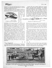
"Flight" Copyright.
; Adjustment for tightening stay-wires.
Latest form of the Robin biplane which is fitted with an 8'cyl. 5O.h,p, Antoinette motor, chain transmission and
two propellers. It has a span of 12 metres, and a plane surface of 52 sq. metres. The feature of this aeroplane is
the pronounced curvature of the lower plane.
278
�
SEPTEMBER 18,
tion in the first instance, but for our own part we favour
the other aspect of the case for the two points which it
has in its favour, the first being that the better a machine
is made the less liable is it to give trouble any way,
and the second being that when it does get smashed
a well-made article is always more easily and satisfactorily
repaired than one which is half a wreck to start with.
Moreover, there is always the consideration that a
1909.
supply ; it has a weight of 36 sq. ft. to the lb., and the
waterproofing is done by a celluloid treatment. The
seams in the complete covering are diagonal, and each
half of a deck, from an extremity to the centre, is practically enclosed with a kind of fabric bag, the edges of
adjacent bags are laced together in the centre, while at
intervals the fabric is tacked down to the supporting ribs.
In order to prevent the fabric being torn, a thin strip of
wood is placed between the
fabric and the heads of the
nails.
Main Decks.
The skeleton framework
on which the surfaces are
stretched consists, for each
deck, of a pair of transverse
spars having a section 1 in.
deep by 11 ins. At the ex" Flight " Copyright.
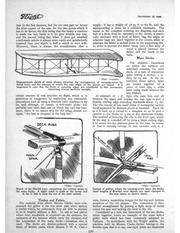
Diagrammatic sketch of main planes, showing the arrangement of warping-wires (in tremities these spruce spars
dotted line), and the manner in which the rear edges of the planes are flexed. It is are joined together by a
important to note that the front or entering edges are unaffected by this movement, piece of bent elm, a scafe
remaining always perfectly straight.
joint being made between the
two timbers,
certain amount of risk attaches to flight, which it is
fore and aft
At intervals of 1 ft.,, light
g ribs pass
p
gratuitous to exaggerate by neglecting any reasonable
between the spars and overlap the rear spar to give a
proportions such as using a decently built machine to fly
flexible trailing edge extending rearwards about 15 ins.
on, and although, of course, a well-made glider will
The ribs consist of two small strips of rectangular section
probably cost more than one on which less care has been
wood separated by distance pieces at intervals. Each rib
spent, there is no reason why the old adage should not
as it is built up is curved to a template so as to give a
apply, " the best is cheapest in the long run."
camber to the decks of 3 ins. at the maximum versine.
The method of fastening the ribs to the front spar, which
by the way is rounded off to form a blunt cutting edge,
is to secure the last distance piece to the spar by screws
DECK R.I&S
so that it virtually belongs to that member and, as it
" Flight" Copyright.
"Flight" Copyright.
Sketch of the flexiWe-joint connecting the vertical struts to
the main decks. A slight notch is made at the lower end
of the U bolt to keep the eye of the strut central.
Instead of pulleys where the warping-wires leave the decks,
short lengths of Bowden wire sheath are used clamped to
the rear spars, as shown above.
Timber and Fabric.
were, forms a supporting tongue for the top and bottom
members of the rib proper. The connection is then
further strengthened by putting a light strap of metal
round the spar and tacking the ends to the rib.
Considered as a unit, the framework of the two decks,
taken together, forms an example of the usual lattice
girder work which has been commonly adopted on
biplanes. In accordance with the Wright system, the
machine built by Messrs. Clarke further belongs to the
flexible type, that is to say, non-rigid joints are employed
The material from which Messrs. Clarke have constructed the glider is for the most part silver spruce,
a timber which, we understand, they are able to procure
in 20 ft. lengths without a flaw. In one or two places
where bent woodwork is required—as, for instance, the
extension of the runners which carry the elevator, and
the extremities of the main decks—American elm is
used. The decks are double-surfaced with a special
fabric of British make, which Messrs. T. W. K. Clarl.e
570
�
SEPTEMBER I S , 1909.
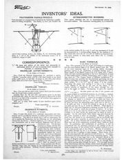
INVENTORS' IDEAS.
FEATHERING PADDLE WHEELS.
INTERCONNECTED RUDDERS.
T H I S describes an arrangement of eccentrics for feathering a paddlewheel for lifting aeroplanes. The blades, A, have just reached the
THIS patent describes the use of interconnected vertical and
horizontal rudders. The horizontal steering-plane, A, is connected
end of their working stroke; the blades, B, are feathering, while
those at C are at the middle of the downward stroke.—E. E.
Lindkvist, 16,941 of 1908.
to the vertical rudder, B, by a rod, C, and any movement of B will
be accompanied by a corresponding change in the position of A.
The claims also cover the use of a pair of rudders so connected that
they move towards or away from each other.—H. C. Lobnitz,
9,235 of 1909.
; BASIC FORMULA
CORRESPONDENCE.
• » • The name and address of the writer (not necessarily for
publication) MUST in all cases accompany letters intended for
insertion, or containing queries.
PROPELLER ADVERTISEMENTS.
To the Editor of FLIGHT.
SIR,—Until the Watford Engineering Co. produces a i4l-in.
" Beedle " propeller which will lift 2 lbs. dead weight at any speed
under 1,580 r.p.m. on less than 7 5 amps at 200 volts, they cannot
justly claim not to have been beaten by the " Cochrane."
Yours faithfully,
WILLIAM COCHRANE.
PROPELLER
THRUST.
,
To the Editor of FLIGHT.
SIR,—Can you tell me what is the utmost thrust per horse-power
that can be got from a perfect propeller ?
Quoting from the lift and drift experiments given in the issue
of February 6th, 1909, the best curvature gives a ratio of lift to drift
of 15 to I, so that in the propellers so far evolved there appears to
be a great loss of power.
Will you or some kind reader of your excellent paper please
enlighten me?
... .-.
Yours respectfully,
Marple.
II. G. DAWSON.
INGENIOUS FITMENTS.
To the Editor of FLIGHT.
SIR,—I trust this sketch of a combined strut-socket and wirestrainer will be of sufficient interest to readers of FLIGHT to warrant
reproduction. The idea is so simple that it will be unnecessary for
me to explain the illustration, but the following are the advantages
claimed for the device :—Extreme lightness, as it takes the place of
two turnbuckles, and in some instances dispenses with six wireattachment eyes. For the same
reasons it is cheap, and the wire
is attached much more easily and
quickly than by other methods.
It offers no head resistance, being
immediately behind the socket
and strut, and it has no left-hand
screws, which are often difficult
to replace in case of loss. Patents
are pending which cover several
variations of this arrangement,
and I shall be pleased to send
further particulars to prospective users. I may mention that Messrs.
Handley Page, Ltd., are taking up the manufacture of same, and
can give early deliveries. Wishing FLIGHT continued popularity
and success,
I am, yours faithfully,
Elland.
F. BROCKWAY.
' To the Editor of FLIGHT.
SIR,—The conquest of the air is still proceeding at a rapid pace,
and the cross-Channel flight of M. Bleriot marks a new era. One
of the most important signs of its coming within thoroughly
practical regions is the production of formulas bearing upon it.
Major Squier, of the Signal Corps of the U.S. Army, who, I understand, has been recently appointed by the U.S. Government as head
of their newly-created Aviation Department, read a paper a short
time since, on " The Present Status of Military Aeronautics,"* in
which he went very carefully into the principles governing the construction and flight of aeroplanes. He gives the formula for a single
plane surface, P — 2 k<r A V2 sine o, where P is the pressure
supporting the plane, and causing it to rise, k is a constant,
a the density of the air, A the area of the plane, V the
relative velocity of translation of the plane through the air,
and a the angle of flight. Transposing, he gives the equation
p
A F 2 = i —; •
• He then points out that, if the pressure and
r
2 X-o- sine a
>
r
the angle of flight are maintained constant, in, of course, a constant
1
medium, the equation assumes the form, A V' = constant, or the
area of the surfaces required to support an aeroplane is inversely as
the velocity at which it is driven. At 40 miles per hour, the
supporting area measures 500 sq. ft. If the speed were increased to
60 miles per hour, the supporting plane need only be 222 sq. ft. ;
at 80 miles per hour it would be reduced to 125 sq. ft. ; and at
100 miles per hour 80 sq. ft. would be sufficient. These figures, I
think, are of very great importance, showing, as they do, the great
value of the speed at which the aeroplane is driven. If an aeroplane is to be of any value for attack, it must be made as small as
possible, or in other words, the speed must be raised as much as
possible. On the other hand, Major Squier also gives formulae for
the power required to drive an aeroplane. Without going very
much into the details of the calculation,'it may be mentioned that
he gives the power required, as proportional to the cube of the
speed. All of these formulae will be recognised as very similar to
those that rule in all engineering problems, where fluids are dealt
with. In ventilation, and compressed air problems, it will be
remembered that the resistance opposed to the passage of the air
varies as the square of the velocity, and the power required to move
the air varies as the cube of the velocity. Moving an aeroplane, or
any airship through the air, is in fact the converse of moving air
through any duct or gallery, or mine passage. Major Squier points
out also how important the question of skin-friction is. Of course,
skin-friction increases with the area of the supporting planes. Skinfriction must be a very large item in the resistance offered to the
passage of dirigible balloons through the air. Skin-friction again is
the important item in the problem of moving air through ducts,
&c, and in moving ships through the water. It is the rapid increase
of the skin-friction, with the velocity, which causes the great increase
of power required to drive the great ocean liners, and the large battleships, through the water.
W. WiNDHAM.
* This Paper was reproduced in full in FLIGHT over a series of issues
commencing February 27th, 1909.
�
OCTOBER 9,
1909.
FURTHER DETAILS OF SANTOS DUMONT'S No. 20
side of the aviator's seat. The centrally placed leve
which lies behind the back of the pilot operates th>
wings as described last week, but it is interesting t<
observe that M. Santos Dumont ha
a piece of brass tube some two o
three inches long sewn on to the bad
the very full illustrated description
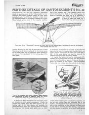
which we gave last week of the " Demoiselle," we now
reproduce four further sketches which we have made
specially, in order to still further elucidate certain minor
but important details for the benefit of readers of FLIGHT.
These include a front view of the complete machine,
SUPPLEMENTING
Front view of the " Demoiselle," showing the main stays for the leading edge of the wings as well as the warping
wires passing from the seat.
another showing the tail with its universal-joint, a third
illustrating special fitments adopted for the tubular struts
for the main girder, and the remaining sketch relating to
the system of lacing adopted for the trailing edge of the
main plane.
of his jacket, so that when he is seated in place the tub<
slips over the lever in question and enables him to rel)
upon a positive action when he leans over to the right oi
left. In the same sketch, too, may be observed the
position occupied by the two chassis wheels.
As regards the tail, this in itself is constructed with t
bamboo rim as mentioned last week, but the universal
swivel is formed entirely of pieces of tube, in the use o
which the inventor is very clever. The intermediate
T-piece has one vertical arm that swivels in the brasec
View of the complete tail, which is moved bodily upwards
and downwards as well as sideways, about the special
swivel-joint shown in greater detail in the inset.
Tubular struts of oval section fit into sockets
brased on to thin metal collars in order to stiffen
the main girder-frame. As will be observed
above, these collars are rendered rigid with the
main bamboos by means of small clamping
plates and screws.
In the first of these illustrations two important points
are brought out with special prominence. Firstly, the
tubular stays which form the chief supports for the
leading edge of the main planes, and secondly, the
precise manner in which the operating-wires for warping
the wings are run through small guide-tubes on either
sockets which couple up the main bamboos together, and
the tail itself swivels upon the horizontal arm of the
T-piece. Our sketch also shows the connecting-wires that
pass to the hand-lever on the right and the hand-wheel
on the left for elevating and for steering respectively,
and also denotes the presence of the small helical springs
619
C 2
�
OCTOBER 9,
In the above sketch is shown the lacing bymeans of which the rear edge of the main planes
is held taut about a strong wire, which is itself
clipped to the ends of the ribs. The surfaces of
the wings are in this way stretched tightly.
that automatically take up any slack or allow for any
contractions in the operating-wires.
It will be remembered that we spoke last week of the
ignition-switch that is fitted into the steering-lever for
enabling the engine to be stopped at a moment's notice
if necessary. In addition to the three controls for the
monoplane proper, it should also have been stated that
the throttle-valve on the engine is coupled up to a pedal
conveniently placed for the left foot. In this way the
two engine-controls can be manipulated, although the
operator's hands need never leave the even more important lever and wheel on which the evolutions of his
flyer depend so greatly. Our other illustrations with their
inscriptions readily speak for themselves, and hence n&
further reference need be made to them here.
CLOSE OF THE BERLIN
during the last four days of the Berlin flying
week Rougier, Latham and Farman each made long
flights, no records were broken, and so the proceedings
became rather monotonous. The unfortunate disputes
over money matters did not improve affairs. The
semi-official announcement that the Bleriot monoplane
was " seized " was subsequently officially denied, and, as
a matter of fact, the machine was sent on to Cologne on
the 30th ult. The poor organisation was, however,
responsible for two further disputes on the penultimate
day, when the aeroplanes of Senors Sanchez Besa and
Edwards were detained, as it was alleged they had not
fulfilled their contracts.
Taking up the story of the actual flying from
where we had to break off last week, at the conclusion
of Wednesday's proceedings, on Thursday, the 30th. ult.,
the hero of the day was Latham, for he succeeded in
improving upon Rougier's record for the distance prize,
flying 33 rounds of the course—82*5 kiloms.—in
1 hr. 22 mins., and only stopping because of the falling
darkness. An amusing incident arose out of this.
Latham, in trying to land in the dark, was unable
to quite clear a lamp-post, and when he did reach earth
he found himself in the clutches of a policeman,
who wanted to arrest him for damaging the lamppost. Eventually, however, the committee set matters
right.
Those German polizei are real humorists.
Rougier was the only other one to do anything noteworthy, and he flew with a passenger—Duray—to a
height of 70 metres. Both Baron de Caters and Leblanc
also made flights, but they were quite short. The following day Rougier came to the front, and his trip of
130 kiloms. for the distance was not improved upon
before the end of the meeting.
His time was
2h. 41m. 50s. and like Latham on the previous day he
was only prevented from continuing by the gathering
darkness. Farman also made an a'ttsmpt for the distance
prize, but he could only manage 33 laps, or 82-5 kiloms.
in 1 hr. 30 mins. De Caters also made a dozen turns
round the course, his time for the 30 kiloms. being
33 mins. 30 sees. At one time all these three flyers were
in the air together, and the spectacle had all the appearance of a real race, as the machines were of similar type.
On Saturday last Farman made another attempt for
the Distance Prize, but was unfortunate. After flying
steadily for 1 hr. 3 mins. motor troubles began to develop,
and he had to come down. Other than this the afternoon
crowd had very little to see except a couple of short flights
by de Caters and Molon. Rougier had dismounted his
ALTHOUGH
1909.
MEETING.
engine in order to make some adjustments, and it was
well after five o'clock before he was ready to take the air
again. Then, after a couple of trial flights to see that
everything was in order, he went up with Duray and;
made five circuits of the track, 1375 kiloms. in
17 mins. 27 sees. He afterwards took up Col. Pelle, one
of the military attaches to the French Embassy, and flew
with him once round the track. Very little out of the
ordinary was done on the last Sunday, and although
Latham hoped to be able to retrieve his misfortunes, he
was doomed to disappointment. For some reason thj
motor on his machine could not be got to work properly
until ten minutes after the closing time, when he flew to
a height of 178 metres, but it was too late. Rougier made
his try for the height prize earlier, and attained an altitude
of 158 metres, sufficient to give him the first prize. He
also made a splendid flight accompanied by M. GaorgesPrade, during which he rose to a height of 70 metres and!
completed a dozen circuits, or about 30 kiloms., in
36 mins. Farman made a gallant attempt in the distance
contest, and kept going for two hours, but owing to one
of the wings touching the ground after the first twenty
minutes, the time officially recorded was not sufficient to
improve his position. He also had a try for the passenger
prize, but only completed one of the four laps.
Altogether the meeting was not quite the success it
might have been, a result largely due to the want of
proper organisation. One of the chief complaints levelled
against the management was the long distance of the
ground from the railway station, while the cheap seats
were so far away from the grand stand that it was only
possible to tell what was going on by the aid of glasses.
RESULTS.
Distance Prize.
1. Rougier (Voisin). Berlin Cup and 40,000 marks
(£2,000)
130 Idioms.
2. H. Latham (Antoinette). 15,000 marks (^750) 82*5 ,,
3. H. Farman (Farman). 5,000 marks (£250) ...
83*09 „
If he had not touched ground at the 30th kilom. in his long,
flight, Farman's record would have been n o kiloms.
Speed Prize (20 kiloms.).
1. H. Latham (Antoinette). 8,000 marks (£400)
18m. 46fs.
2. H. Farman (Farman). 2,000 marks (£ 100) ... 22m. 20s.
3. De Caters (Voisin)
... 22m. 47*s.
Altitude Prize.
1. Rougier (Voisin). 10,000 marks £500)
... 158 metres.
2. Latham (Antoinette). 5,000 marks (.£250) ...
85 ,,
After the cloje of this event Latham flew to a height of 178 m.
Passenger Prize (10 kiloms.).
I. Rougier (Voisin). 10,000 marks (£500).
620
�
OCTOBER 16,
and seems to be a very good solution of a particular difficulty which
has to be overcome. Wheels are necessary for running along the
ground when starting, but skis are better suited to withstand the
shock of landing. In those devices which combine both members,
the wheels are mounted so that they are normally some six
or eight inches below the level of the runners. They are suspended
1909.
is not a great deal in this matter which calls for special comment as
the result of an examination of the actual machines. Sometimes
the fabric is hardly fastened down at all, at others it is stuck down
with cement or tacked down with nails to occasional ribs. A pre-
ELASTIC.
" Flight" Copyright.
P A R I S F L I G H T SHOW.—Sketch illustrating the use of
wheels in conjunction with ski for the chassis of an aeroplane.
in such a manner as to be capable of taking the dead weight of the
machine, but on sudden impact with the ground the wheels rise and
the runners take the load, thus preventing damage to the wheelmounting which is otherwise liable to take place. Even on a socalled smooth flying ground a chassis wheel gets quite an amount of
bumping about; in fact, it is rather remarkable that more accidents
have not happened with this member.
Elastic Springs.
The suspension at present employed almost invariabiy includes the
use of elastic springs. These springs are built up out of innumerable
fine strands of elastic until they form a cable which averages from an
inch to an inch and a quarter in diameter, according to the load.
The cable is covered with a woven cotton fabric and is fitted with a
"Flight" Copyright.
P A R I S F L I G H T S H O W . —Sketch illustrating how Ithe
surface fabric may be protected from the nails which secure
it to the rib by the use of rib laths. T h e above sketch
illustrates a portion of a wing tip seen from beneath.
caution which some builders take in the latter case is to place a thin
strip of wood outside the fabric to prevent the nail heads from
tearing through. The method adopted by Santos Dumont of sewing
the upper and- lower surfaces together between the ribs is interesting
and uncommon. Many firms are using strips of aluminium
" Flight" Copyright.
" Flight " Copyright.
P A R I S F L I G H T SHOW.—Portion of an elastic spring,
showing the brass ferrule which is clamped to its extremity
to provide a means of attachment to the machine.
clamp at each end, so that it can conveniently be attached to its
anchorages. The price which the accessory dealers are asking for
these elastic springs suggests a very keen eye to the main chance, in
spite of the present cost of rubber; for a single " spring" about
12 ins. in length 35 fis. was demanded.
P A R I S F L I G H T S H O W . — Sketch illustrating Santos
Dumont's method of fastening the fabric by sewing the
upper and lower surfaces together between the ribs.
bent into c section for the leading edges of the decks,
as it is light, and gives a smooth continuous front.
A
method of finishing off the trailing edge, ; which is at
once effective and neat, is to run a steel wire through
a pocket which can be conveniently made by turning back
the fabric. Incisions in the cloth expose the wires at intervals
coinciding with ribs of the framework, over the ends of which it can
T i m b e r and Steel.
Turning to the materials used for the construction of aeroplanes,
timber is unquestionably still more popular than steel, although there
are not wanting prominent designers, like M. Esnault-Pelterie, who
use steelwork very largely in their machines. Spruce for spars and
other fairly bulky members, and ash for the lighter pieces, especially
those which are curved, are the most common woods employed.
Tubular steelwork for the chassis is, of course, frequently to be seen.
Deck Surfaces.
The surfacing of the decks or wings is in most cases carried out
with rubber-proofed fabric, although in a few instances fine untreated
canvas is considered adequate. From the many letters we have
received on the subject, we are led to suppose that the method of
fastening the surface material to the skeleton framework of the deck
presents points of special difficulty to our readers, but in reality there
" Flight" Copyright.
PARIS FLIGHT SHOW.—Sketch illustrating the use o£
sheet aluminium for the leading edge of the main decks.
65O
�
OCTOBER 30,
1909.
THE ANTOINETTE
MONOPLANE.
(Concluded from page 662.)
Thick Wings and their Buoyancy.
T H E i, thickness of the wings already mentioned is a
result of adopting a system of construction designed to
secure a maximum of strength with a minimum of weight,
but it may be remarked en passant that the volumetric
capacity which this thickness confers on the wings
showed itself to be of more than incidental advantage
kept exceptionally taut by the large number of ribs that
go to make up the wing framework.
The outstretched wings form a pair of cantilevers, of
which the main transverse spars are the principal
members. Each spar is constructed on the latticegirder principle, and tapers in dipth towards the
extremity. At its inner end it is mounted in a substantial bracket, which is attached to the body of the
machine. This bracket, in the case of the rear pair of
spats, is pivoted, as shown in an accompanying sketch,
MAIM
SPAH
so that it can rock bodily
QJIDE.
when the wings are
warped.
In addition to these
main transverse spars
HOLLOW
y
POST
there are other transversemembers unattached to
the body of the machine,
but serving, nevertheless,
to give strength to the
wing framework. Across
these spars pass the
curved main ribs, which
".Flight"
Copyright.
"Flight" Copyright.
" Flight" Copyright.
are spaced at intervals
The Antoinette Flyer. of about 18 ins.; they
The Antoinette Flyer. — The Antoinette Flyer.—Sketch show—Sketch showing how
Sketch showing how the main ing the attachment of the axle-strut
the stay-wires for the are also built up latticespars in the wings are trussed to the sliding-guide on the vertical
wings are attached to girder fashion. Between
by hollow posts and diagonal pillar. The strut is of hollow wood,
and has a steel end-piece.
the mast.
wires.
the main ribs light open
ribs, constructed without the lattice bracing, are provided for the addiin the matter of buoyancy when Mr. Latham so
tional support of the surface fabric. Near the body of
unfortunately had to alight on the sea in his crossthe machine these latter members have a spacing of only
Channel flights.
about 2 ins., but elsewhere their distance apart is twice
Of the other special features, it is necessary only to
as much. As the result of this very carefully thoughtmention the boat-like body and the distance of the tail
out system of construction, the manufacturers claim that
behind the main planes, which distinctly seems to be
their wing framework for wings of 15 to 25 square metres
relatively greater than on other machines.
in surface can be produced as light as 1 kilog. per
Wing Construction,
square metre, not including the fabric.
The wings are built up upon two transverse main
In addition to their mounting on the body of the
spars, neither of which, however, forms the edge of the
machine, to which reference has already been made, the
wing, as is so commonly the case in the decks of
wings are further supported by wires, which radiate (rom
biplanes. Both the leading and trailing edges of the
a central wooden mast projecting above the body.
Antoinette wings are sharp, and their upper and lower
These wires are attached to the main transverse spars
surfaces (made of Michelin rubber-proofed fabric) are
about the centre of their length, and each spar is itself
THE ANTOINETTE FLYER.—In the above illustration of an early Antoinette monoplane the arrangement of
the spars and ribs and th* framework of the wing can be seen through the surface material. The above view also
shows the lattice-girder main frame, which in the latest machines is covered in.
681
�
OCTOBER 30,
1909.
independently trussed by a vertical
post and diagonal wires. The posts
used for this purpose are, like the
main-mast, of hollow construction,
and each is one continuous member from top to bottom. It is
placed a little to the side of the
main-spar which it trusses, being
notched to receive that member.
This arrangement avoids the
necessity of dividing the post at
the centre. Each end of the post
is fitted with a steel ferrule, on the
outside of which is a screw thread.
A suitable attachment for the staywires is provided by a light steel
plate threaded over the ferrule,
and clamped between two nuts.
The Body and Chassis.
The body of the machine consists of a hollow V-section lattice
girder, the fore part of which is
encased with a veneer of cedar,
"Flight" Copyright Photo.
THE ANTOINETTE FLYER.—View of the latest model, showing the cedar
hull. The framework under the surface is illustrated in another view, showing
an earlier type.
is a very light skid at the rear to protect the
rudder. The forward skid is made of ash,
and has a maximum square section of about
2J ins. Its extremity is laminated and
curved upwards, the tip being protected by
a steel place.
The Tail.
At the rear of the body is the tail, consisting of two fixed planes, and three
movable planes. The fixed members include a vertical and a horizontal plane
arranged like the feathers on the shaft of an
arrow, and their object is to fulfil much the
same purpose in respect to the flight of the
machine. The movable members are virtually extensions of these planes ; the continuation of the horizontal plane forming an
elevator, while the continuation of the
vertical plane makes a rudder. An additional rudder .working in unison with the
first is provided beneath the elevator.
; ;
Control.
The control of the machine is effected
by means of two hand wheels and a pedal.
The wheels are placed vertically on each
side of the pilot's seat, and lie just
outside the body of the machine. That on the right
when moved forwards dips the trailing edge of the
elevator. A
SPAR
similar movement of the
left-hand
wheel warps
the trailing
edge of the
right-hand
m a i n-w i n g
downwards.
Pressing for" Flight" Copyright.
ward the right
The Antoinette Flyer.—Sketch showing
foot puts the
bow the rear spars in the wings are
trailing edge
pivoted to the frame to facilitate
of the rudder
warping.
THE ANTOINETTE FLYER.—In the above view of the tail the
triangular horizontal plane which forms the elevator is shown depressed
for descent, while the two triangular rudders are shown set over for
turning to the right.
and pointed like the bows of a boat. Further aft the
cedar gives place to a covering of rubber-proofed fabric,
and this material is also carried over the top side of the
frame, thus forming a kind of deck. An open cockpit is
provided for the accommodation of the pilot's seal.
The machine is supported on the ground by a pair of
small pneumatic shod wheels, attached to an axle which
is provided with pneumatic suspension. This latter is
obtained by means of a plunger in a steel tube ; the tube
is a downward continuation of the main-mast already
mentioned. The bracing of the axle to a sliding collar
which rides on the outside of the stationary tube, and
thereby prevents the axle from tilting, is effected by
hollow wood struts fitted with steel forks spliced in their
extremities.
An ash skid is provided in front of the machine to
prevent the propeller from hitting the ground, and there
632
�
NOVEMBER 13,
1909.
ORIGINALITY IN MONOPLANE DESIGN.
AN EXPERIMENTAL MACHINE
unusual features have been embodied in the
monoplane of which we reproduce a side elevation
herewith, and which i, being constructed by the Aerial
Manufacturing Co. of Great Britain and Ireland for a
VARIOUS
NOW BUILDING IN LONDON.
::
the leaf springs absorb shocks due to any roughness of
the ground.
Needless to say both the above-mentioned systems
need to be given a practical trial before any conclusive
statement can be made concerning their value. Other
novel details are being embodied at the same time on
SMALL PLANK ON RUDDER
RUDDER
client of theirs. First
and foremost it will be
observed that various
subsidiary planes are
introduced locally at
different spots with the
object of assisting in
the distribution of strains
within the machine itself, while even the
petrol tank is shaped
similarly, although it is
only the width of the
main framework. For
convenience of reference, the main plane is shown in
black, the small supplementary planes, including the
elevator, are cross-hatched, and the petrol tank is merely
shown in outline in the drawing.
Hardly less noticeable is the curious double-hinged
framework, with its wheels in front, that is intended to
facilitate starting and alighting. In the position indicated
by the full lines, the two small planes carried by it
(double cross-hatched) serve to assist in lifting the
machine, while since the lower wheel leaves the ground
last, the full weight is only taken after a fair altitude has
been attained. The further object of the arrangement
is to cushion the descent by allowing the lower wheel to
reach the ground some time prior to arrival of the
complete machine, and then, as the hinges allow the
framework to fold up into the position indicated by the
dotted lines, to cause the small planes to act as brakes,
retarding further forward progress, at the same time that
this particular monoplane, and hence future experiments
with it will be watched with considerable interest. The
machine itself is of quite large dimensions, as may be
judged from the scale on the drawing, the length overall
being no less than 44 ft., and the span being also 44 ft.
from tip to tip of the wings. An engine of novel design,
developing about 50-h.p., is moreover, we understand,
to be employed in conjunction with a 10-foot 4-bladed
propeller. In due course, too, it is hoped that the
machine will be placed on view in London, but the
makers are unable to allow it to he seen in their works at
the present time as they are also carrying out other
commissions there, in connection with which they are
pledged to secrecy.
•
A n Aviation Catalogue.
A REMINDER that flight is rapidly attaining a commercial position is to hand in the shape of a catalogue
issued by the Richelieu-Automobiles, Paris. It contains
particulars and prices of Bleriot, Antoinette, Wright,
Voisin, and R.E.P. aeroplanes, and dirigibles of the
Astra, Lebaudy and Zodiac types, as well as various
motors specially adapted for flying machines. In this
connection special illustrated prominence is given to the
Wolseley 8-cyl. V motor, and the prices quoted for the
various aeroplanes are given either without motor, with
ordinary motor, or with Wolseley motor, a striking compliment to the British product. The catalogue also
contains particulars of hangars of various sizes, and prices
of many accessories used by aviators.
Flying at the Antarctic.
IN view of the several proposals with regard to the
use of airships and aeroplanes in connection with the
exploration of Polar regions, it is interesting to note that
in the course of his remarks at the R.A.C. recently
anent his experiences in the Antarctic seas, Sir E. H.
Shackleton, C.V.O., explained that it was almost
impossible for any work to be done by flyers in the Far
South regions. There was always a very strong wind
blowing across the plateau, so that aeroplanes were out
of the question, while balloons would be of no use, as
at a height of 700 feet the gas would contract, and the
valve once opened would not again close properly.
Thus, Antarctic research was narrowed down to a
question of men, dogs, and motor cars.
\
Sketch of a bracket for joints of framework of aeroplanes
which is being manufactured by the Aerial Manufacturing
Company of Great Britain and Ireland, of Upper Charles
Street, Finsbury. Great rigidity and lightness are claimed
for these, whilst the price is quite small, we understand.
The sketch shows a single bracket, and also one each side
of a joint, making a very rigid fixture, with wiring connection included.
726
�
NOVEMBER 13, 1909.
German Airship Manoeuvres.
v
DURING the latter end of last week the four German
military dirigibles continued their manoeuvres at Cologne,
and on the 4th in^t. a series of altitude trials were carried
out. "Parseval III" rose to a height of 800 metres,
while the "Gross II " and '• Parseval I " went up as high
as 1,200 metres; but the "Zeppelin I I " was unable to
take part, owing to some motor defect. Just before
midnight on Tuesday week the airships, with the exception of " Pdrseval I," set out for a night cruise, and
carried out a series of imaginary attacks on the fortress
of Coblentz. They all remained in the air for the
stipulated time of eight hours. On Saturday the
manoeuvres came to an end, when the four airships
sailed in procession over the city, passing round the
double tower of the famous Cathedral.
Armament For and Against Dirigibles.
FROM Austria comes a little information regarding
two inventions which are at present receiving the attention
of the Ministry of War of that country. One, the idea
of Louis Bertuch, is for a torpedo, which could be fired
from the ordinary Army rifle and yet would effectively
disable the largest airships at a height of 1,000 feet.
The second idea, evolved by an engineer named Gratz,
consists of a projectile which could be discharged
from an altitude of more than 1,400 feet from a dirigible
of any size.
An American Balloon Record.
IN connection with the " Centennial " Races held
at St. Louis, Missouri, on October 4th, 1909, Mr.
Clifford B. Harman, an Ae.C.A. pilot, in the balloon
" New York " (80,000 c.f.) set up a new American endurance record of 48 hours. The balloon, which was
built of vulcanized rubber material made in America, left
the Aero Club Park at St. Louis at 5.15 p.m. on
October 4th, and landed at 5.41 p.m. on October 6th
at Edina, Missouri. The distance between these points
was 150 miles, but a much greater distance was really
traversed, as the winds were extremely variable, and the
balloon kept travelling in a circuitous direction. The
highest altitude reached was 24,200 ft., and the temperature varied from 90° F. to 39° F.
CORRESPONDENCE.
The name and address of tke writer (not necessarily ft? fiubtiration) MUST in all cases accompany letters intended for insertion*
or containing queries.
A DEFINITION OF " V2."
WIRE BRACING.
To the Editonof FLIGHT.
To the Editor of FLIGHT.
~ S I R , — I have no doubt that a number of readers of FLIGHT who
are building aeroplanes have a great difficulty in bracing up their
machines. I am building a biplane, and am using the system of
which I have enclosed a rough sketch, and find it works most
satisfactorily either for the planes or outriggers or any other part. It
SIR,—Referring to the account of the Wright Bros.' early experiences (by Wilbur Wright), I note that the curve for the decks is
given as having been originated by them, whereas I have always
been under the impression that it was the strict and ideal Lilienthal
curve.
Did then Lilienthal use a plane with just an ordinary semicircular curve ?
I shall esteem it a favour if you can enlighten me on this point,
and give me a definition of V2 at the same time, as I continually
stumble upon it in the columns of your valuable paper.
Yours faithfully,
Chiswick.
is what I call continuous bracing ; the wire is fitted with a bolt at one
end, goes under one strut and over the other, and is pulled taut with
an adjuster made of a spoke and nipple and a bent plate.
This makes a good sound job, and I trust it may be of some use
toUhe readers of FLIGHT.
Yours truly,
Wandsworth.
WALTER YEATMAN.
,-=rr
A
QUESTION OF WEIGHT.
To the Editor of FLIGHT.
WALTER E. FOX.
[The tables compiled by Lilienthal relating to the lift of aerofoils
were based on his experiments with cambered surfaces having the
curvature of an arc of a circle. There is not, so far as we know,
any record of Lilienthal having moved the maximum versine of the
camber nearer the leading edge, nor have we found any record of
any experimenter having done so prior to the Brothers Wright.
The symbol V2, which is so commonly used in articles on flight,
should be read " square of the speed." It implies a value obtained
by multiplying the speed by itself. Thus, if the speed is actually
10 miles an hour, then V2 equals 100. Air resistance is proportional
to V2. That is to say, the ratio of two resistances, one being at
10 miles an hour and the other at 20 miles an hour, will be represented, not by the figures 10 and 20 themselves, but by their squares,
which are 100 and 400 respectively. It will be noticed that the
greater resistance is thereby four times instead of only twice as great
as the smaller.—ED.J
BROOKLANDS AND FLIGHT.
To the Editor of FLIGHT.
• .:. -
SIR,—Having in view the graat interest which the original use of
Brooklands as an aviation ground has aroused, it might interest you
to see and possibly to publish the enclosed letter, which I have
forwarded to the many applicants we have had for sheds and
accommodation at Brooklands.
Yours faithfully,
F. LINDSAY LLOYD, Clerk of the Course.
& SIR,—I am making a model monoplane with a total area of
7^jsq. ft. Will you or one of your readers of your excellent paper
let me know what the maximum weight of the model should be with
engine complete, i.e., to obtain good results ; also what h.p. and
dimensions of propellers. Wishing your paper every success,
Yours faithfully,
M. M. W.
733
[Enclosure.]
" W i t h reference to your application for facilities for exercising
an aeroplane at Brooklands, I beg to inform you that we are proposing to proceed on the following lines :—
" We will erect and maintain a suitable shed for each tenant, and
let same for the rents mentioned below. For these payments the
�
JANUARY 8,
(/IjGHf
1910.
THE LILIENTHAL AND PILCHER
GLIDERS COMPARED.
{Concluded from page 8.)
W i l l o w and B a m b o o .
open umbrella. In order to close the wings, it was only
necessary to unlash the attachment between the front
T H E R E is a subtle difference in the construction of
edge and the main frame, when the ribs would then all
these two gliders, otherwise so much alike, which is
swing round one above the other into any convenient
directly attributable to the difference in the materials
position.
employed, for where Lilienthal used willow sticks, Pilcher
adopted bamboo. Both had, it will be seen, sufficiently
Lilienthal obtained much the same effect, but in his
awkward materials to deal with, but Pilcher, it must be
case the ribs folded up side by side, being hinged to a
central bracket into which their wedge extremities
normally fitted like the spokes of a wheel.
In this machine the hinge centres are 6 ft. apart, and
UPRIGHT
in the Pilcher machine the same points are separated by
a distance of 7 ft. 6 ins. In both cases the hinges are
joined by a wooden beam, but whereas in the Pilcher
glider this member consists of a simple rectangular piece
of wood, in the Lilienthal machine it is a built-up
structure in the form of the letter X ; which system was
MAIN BEM*\
•O
"Flight " Copyright.
Method of attaching the ribs to the wing standards on the
Pilcher glider.
confessed, made a far more engineering-looking job of
his work than Lilienthal, whose constructive methods
are somehow reminiscent of bent-wood furniture. Both
designers embodied the principle of folding-wings in
their machines, and thus both were under the same
necessity of adapting their construction to suit the special
requirements imposed by this important condition. At
the same time, however, both had to provide their wings
when finished with an artificial camber, and it is particularly interesting to compare the two methods by
which these details were accomplished.
T h e F o l d i n g of the W i n g s .
Pilcher, who was working with bamboo, fitted the inner
" Flight" Copyright.
Head of a wing standard on the Pilcher glider, showing
radiating tie-wires.
adopted in order to enable the staying of the wings to be
conveniently accomplished. It would doubtless have
been better had Pilcher attached more importance to the
strains on the main beam of his machine, because it was
that which gave way during his last glide.
P i l c h e r and H i s W i r e .
Pilcher adopted a very different method of bracing
his wings to that employed by Lilienthal,
]ll|illll fllWHUBWrj) in fact, it is in this respect that the
y. *
two machines are most unlike.
He
oocl l u g
relied entirely upon the use of piano-wire
for cambering the surfaces of his wings
to the desired shape, and in order to get the effect
sought he braced each to a central hinge pin consisting
of a bamboo pole some 6 ft. in height, which stood
~~ Stay Wives
up 3 ft. above the deck and projected 3 ft. beneath it.
Radiating from the top and bottom ends of this pole
are a number of wires, for the most part there are three
" Flight" Copyright.
wires attached above and beneath each rib, only the
O n e of the ribs of the Pilcher glider.
two front ribs in each wing having less than this
number.
There are nine ribs in each wing, and
extremities of the ribs of his wings with wooden plugs, to
altogether 50 wires were required to stay them.
which he lashed a loop of iron wire so as to form a ring.
How Pilcher managed to retain all these wires properly
These rings he subsequently strung over the central
taut is a matter for conjecture, but he must have been a
standard, around which each wing spread out like an
man of great patience if he really gave proper attention
19
c
�
JANUARY 8,
I
l/Qggg
1910.
to each of the 100 wires on which the camber of his
surfaces depended. It is no easy matter to adjust wires
used for such a purpose, as no sooner is a slack wire
tightened up a little too much, than it relieves the strain
upon two or three other wires, which become slack in turn.
And Pilcher, it must be remembered, worked before the
days of those very pretty little wire strainers which commonly form a feature in the bracing of modern flyers,
and his method of adjustment must have been as tedious
as it was effective. Each of his wires he fitted with a
curtain-ring—Pilcher was very fond of curtain-rings—and
on the rib he fastened a wire eye. The wires were cut
to a fixed length in advance, and calculated to allow
about an inch between the ring and the eye when in
place. This gap was filled up by a piece of string, passed
several times through each member to give the required
strength, and by pulling on one end of the string a very
minute adjustment could be made in the tension. More
curtain-rings were employed for fastening the other ends
of the wires to the vertical bamboo poles, so that the
wings could be folded without twisting the wires.
Another little device for which Pilcher's construction is
peculiar is his method of plugging his bamboo rods with
wood. The wood plugs were glued into the hollow ends
of the bamboo, which were then carefully lashed with
string. Pilcher was very careful about lashing the ends
of his bamboo poles as he evidently fully appreciated
their liability to split. His use of wire eyes as lugs is
another neat detail well worthy of attention, and these
little fittings he would also lash in place.
L i l i e n t h a r s Stiffening R i b s .
Lilienthal, who very possibly had a natural objection
to the use of a lot of wires, hit upon a very ingenious
method of doing away with some of them, for he
maintained the camber of his wings by the use of
detachable supplementary ribs, of which there were four
placed fore and aft above the deck. These ribs were
strips of wood having an inverted T section, and they
were cut to shape so as to serve as templates. As
their permanence would have interfered with the
" F l i g h t ' ' Copyright.
Method of attaching the supplementary stiffening ribs on
the Lilienthal glider.
folding of the wings, they were fitted in such a
manner as to be detachable, and the method of doing
this was to fasten small steel clamps on to the primary
ribs of the wings, through which the flange of the template
could slide. As the wings were naturally flexible there
was no difficulty in sliding the curved templates in place
from one end, and once in position these members were
fastened by little clips. Their purpose was primarily to
give the wings the desired camber, although they would
of course tend to increase the rigidity of the structure ;
by their use, the necessity for employing a large
number of wires was obviated, in fact, there were only
two tie-wires radiating from each of the vertical posts
mounted above the hinge plates.
Beneath the wings,
however, there was a wire to every rib, but even in this
respect Lilienthal contrived to do without some 78 wires
which Pilcher found necessary.
Relative Cambering-.
It may be remarked that the number of ribs in each
of the two machines is identical, viz., 18, but the camber
and arching of the wings themselves is distinctly different
in the two cases. Pilcher employed an umbrella-like
form, in which the camber may be described as being
of a uniform character. Lilienthal, on the other hand,
flattened the extremities of his wings to such an extent
that the curvature of some of the ribs was virtually
reversed.
The maximum camber on the Lilienthal
glider, as on the Pilcher machines, occurs at the hinge of
the wing, which on the former is situated 18 ins., and on
the latter 2 ft. 6 ins. behind the leading edge. At this
point the camber is deeper on the Lilienthal than on the
Pilcher glider, but on the Lilienthal machine the camber
is almost confined to this point alone, and is far more
concentrated, if the term may be used, than in Pilcher's
construction.
It is known that Lilienthal experimented with cambers
of considerable height in proportion to the chord, and he
has stated that the maximum versine (camber) of the
wing curvature should be less than -jL of the chord, and
preferably only ^ to TV for considerations of stability.
Both machines had the surface material attached
above the ribs.
T h e Framework.
Having compared the wings and supplementary surfaces, it is of interest to consider the main frames of the
two machines, by which we imply that central structure to
which the whole is braced, and on which the pilot
supports his weight.
In the Lilienthal glider this
member is of somewhat peculiar form, and is best
observed by reference to the accompanying plan; it
bears in a marked degree that bent-wood furniture
appearance to which we have already drawn attention.
One of the principal members is an approximately
circular hoop of willow, across which pass in a fore and aft
direction two willow rods that ultimately converge at a
point where the bamboo tail rod emerges from the wing
surface. Transversely across the hoop passes the main
beam to which reference has already been made, and
immediately behind this an orifice is provided in the
surface to accommodate the upper part of the pilot's body.
Two small bolsters attached to the frame rest under the
pilot's shoulders, and the pilot's arms pass through rests
provided for them in the corners of the X-shaped main
beam. Just in front of this beam is another transverse
rod which the pilot can grip with his hands, and in front of
the main hoop member is another bent-wood construction
lashed in place with wicker, the object of this device
being to act as a fender in the event of collision.
On Pilcher's glider the main frame consists of two
bamboo rods spaced 18 inches apart above the main
�
"=r
JANUARY
15,
_
.#»iJTl
1/UGHT]
1910.
CORRESPONDENCE.
* * Tne name and address of the writer
{not necessarily fJr p*Wat<4H,)t MUST in all cases accompany letters intended
or containing
queries.
for
insertion,
C o r r e s p o n d e n t s a s k i n g q u e s t i o n s r e l a t i n g t o a r t i c l e s w h i c h t h e y h a v e r e a d in F L I G H T , w o u l d m u c h facilitate our w o r k of
reference b y k i n d l y i n d i c a t i n g t h e v o l u m e a n d p a g e in their l e t t e r s .
N O T E . — O w i n g t o t h e g r e a t m a s s of v a l u a b l e a n d i n t e r e s t i n g correspondence w h i c h w e receive, immediate publication i s i m p o s s i b l e , b u t e a c h l e t t e r will a p p e a r practically
in s e q u e n c e a n d a t t h e e a r l i e s t p o s s i b l e m o m e n t .
SURFACING.
downwards in the direction of the arr<
. this has the effect of
opening the join, allowing the spliced piece to go further in, and
when released, automatically tightening up the join.
A simple method of attaching the vertical and horizontal stays to
the tail outrigger or fusilage of an aeroplane or glider is shown in
Fig. 2.
[284]
In answer to your correspondent, re-surfacing, I thought
the method I adopted might be useful. I made a number of wood
blocks the shape of the curved ribs, and fastened them in position
on a board thus, with pins, with the heads cut off to keep in
position.
Having stuck one of the main spars to the fabric, I fastened i* to
one edge of the ribs, covered the ribs with adhesive, brought the
•fabric over, and fastened the other spar down, and left until quite
d r y ; carefully removed them from the blocks by raising them with a
chisel, a
...
 Historical archive . public document