Expandable Modular Mixer public doc (PDF)
File information
This PDF 1.7 document has been generated by Adobe InDesign CS5.5 (7.5.1) / Adobe PDF Library 9.9, and has been sent on pdf-archive.com on 11/11/2011 at 17:55, from IP address 188.142.x.x.
The current document download page has been viewed 4649 times.
File size: 6.57 MB (23 pages).
Privacy: public file
File preview
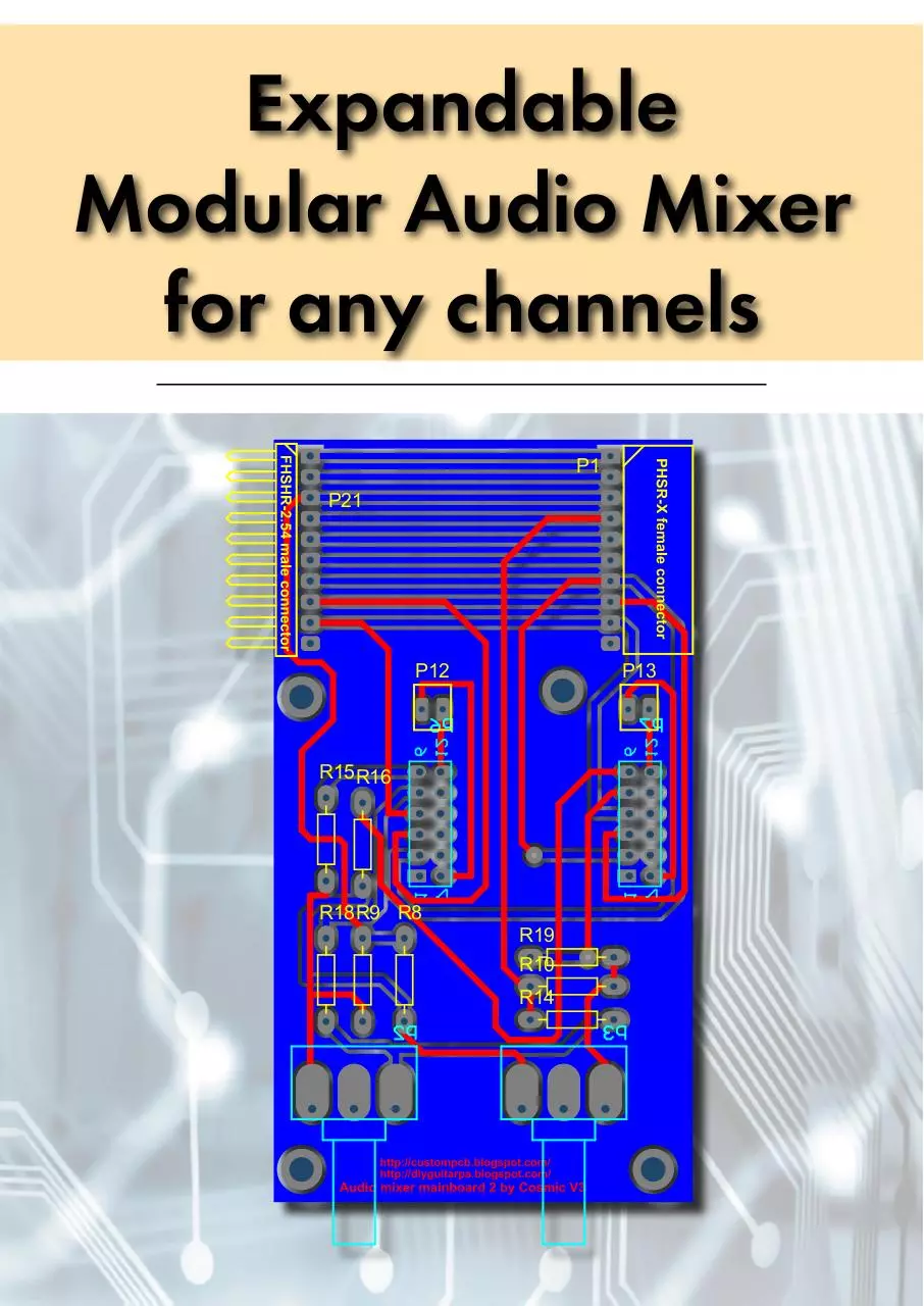
Expandable
Modular Audio Mixer
for any channels
P1
P21
P12
P13
R15 R16
R18 R9 R8
R19
R10
R14
1
2
Printed Circuit Boards for instrument and hi-fi preamps . . . . . . . . . . . . . . . . . . . . . . . . . . . . . 13
Top and bottom PCBs and overlay of stereo jFET preamp . . . . . . . . . . . . . . . . . . . . . . . . . . . . . . . . . . . . . . . . . . . . . . . 14
Top and bottom PCBs and overlay of simple dual OpAmp preamp . . . . . . . . . . . . . . . . . . . . . . . . . . . . . . . . . . . . . . . 15
Top and bottom PCBs and overlay of INA217 microphone preamp . . . . . . . . . . . . . . . . . . . . . . . . . . . . . . . . . . . . . . . 16
Two single OpAmp - stereo universal preamp . . . . . . . . . . . . . . . . . . . . . . . . . . . . . . . . . . . . . . . . . . . . . . . . . . . . . . . . . 18
Two single OpAmp - stereo low noise universal preamp . . . . . . . . . . . . . . . . . . . . . . . . . . . . . . . . . . . . . . . . . . . . . . . . 19
Top and bottom PCBs and overlay of power filters (ver.3) . . . . . . . . . . . . . . . . . . . . . . . . . . . . . . . . . . . . . . . . . . . . . . 20
Top and bottom PCBs and overlay of power filters (ver.2) . . . . . . . . . . . . . . . . . . . . . . . . . . . . . . . . . . . . . . . . . . . . . . . 21
Top and bottom PCBs and overlay of power filters (ver.1) . . . . . . . . . . . . . . . . . . . . . . . . . . . . . . . . . . . . . . . . . . . . . . 22
Top and bottom PCBs and overlay of power filters (ver.4) . . . . . . . . . . . . . . . . . . . . . . . . . . . . . . . . . . . . . . . . . . . . . . 23
Top and bottom PCBs and overlay of power filters (ver.5) . . . . . . . . . . . . . . . . . . . . . . . . . . . . . . . . . . . . . . . . . . . . . . . 24
Switch module for preamps . . . . . . . . . . . . . . . . . . . . . . . . . . . . . . . . . . . . . . . . . . . . . . . . . . . . . . . . . . . . . . . . . . . . . . 25
The PCB of power supply . . . . . . . . . . . . . . . . . . . . . . . . . . . . . . . . . . . . . . . . . . . . . . . . . . . . . . . . . . . . . . . . . . . . . . . . 26
Variable line output board . . . . . . . . . . . . . . . . . . . . . . . . . . . . . . . . . . . . . . . . . . . . . . . . . . . . . . . . . . . . . . . . . . . . . . . 28
Simple headphone amplifier . . . . . . . . . . . . . . . . . . . . . . . . . . . . . . . . . . . . . . . . . . . . . . . . . . . . . . . . . . . . . . . . . . . . . . 29
Balanced headphone amplifier . . . . . . . . . . . . . . . . . . . . . . . . . . . . . . . . . . . . . . . . . . . . . . . . . . . . . . . . . . . . . . . . . . . 30
Images and Picasa galleries about the prototype of this project . . . . . . . . . . . . . . . . . . . . . . 38
Modelling the PCBs of this project before manufacturing . . . . . . . . . . . . . . . . . . . . . . . . . . . . . . . . . . . . . . . . . . . . . . . 39
Examples how to setup the 3 stages of mainboards . . . . . . . . . . . . . . . . . . . . . . . . . . . . . . . . . . . . . . . . . . . . . . . . . . . 40
The selectable prototype of jFEt and OpAmp projects . . . . . . . . . . . . . . . . . . . . . . . . . . . . . . . . . . . . . . . . . . . . . . . . . . 41
Audio mixer with jFET and OpAmp preamps . . . . . . . . . . . . . . . . . . . . . . . . . . . . . . . . . . . . . . . . . . . . . . . . . . . . . . . . . 42
Microphone preamp with INA217 . . . . . . . . . . . . . . . . . . . . . . . . . . . . . . . . . . . . . . . . . . . . . . . . . . . . . . . . . . . . . . . . 43
5
6
-15V
1
2
3
4
5
6
A
GND
7
8
9
10
11
12
A
+15V
GND
Header 6X2A
+15V a1
R9
1
8
P1
1.6kA
6.8K
3
2
C12
47uF 60V
C13
47uF 60V
R13
2.2K
GND
REF
R4
1K
GND
R7
RG_1
RG_2
INA217 AIP
V_OUT
R10
1M
GND
C11 10uF
J1
R11
100K
7
C
6
P2
47kB
U3
OPA137
2
4
3
-15V a2
GND
GND
+15V a2
10uF
47uF 60V
R12
470
C14
100nF
GND
2
C10
3
6
V_IN-
R14
2.2K
U2
OPA137
470
6
V_IN+
R5
1K
C5
C15
Input Jack 6.3
1
2
3
4
5
6
B
7
8
9
10
11
12
GND
GND
R15
100K
10uF
Output
C
Bal In 1 GND
GND
+48V
P4
Header 6X2A
Header 6X2A
12
11
10
9
8
7
6.8K
U1
R1
47K
6
5
4
3
2
1
8
R8
5
7
D2
1N4148
4
R6
B
D4
1N4148
0
1
2
3
4
5
D1
1N4148
4
-15V a1
D3
1N4148
P3
Bal In 2
GND
P6
D
1
2
3
4
5
6
GND
7
8
9
10
11
12
Title
GND
Header 6X2A
Mic and instrument preamp with
assimatrical/simmetrical inputs
Size
D
Number
Revision
A3
http://custompcb.blogspot.com/
http://diyguitarpa.blogspot.com/
Date:
File:
1
2
3
11/6/2011
Sheet of
D:\!Works\..\INA217-MicPreamp-MOD.SchDoc
Drawn By:
4
5
6
The Picasa album about prototype testing
Bill of Materials
Comment
OPA137
Res2
Res2
Res2
Res2
Res2
Res2
Res2
Res2
Cap Pol1
INA217AIP
1N4148
Cap Pol1
Header 6X2A
Input Jack 6.3
Pot Mono
Pot Mono
Cap
Mainboards for any channels expandable modular audio mixer . . . . . . . . . . . . . . . . . . . . . 31
Schematic, BOM and PCB for any channel mixer mainboard stage1 . . . . . . . . . . . . . . . . . . . . . . . . . . . . . . . . . 32
Schematic, BOM and PCB for any channel mixer mainboard stage2 . . . . . . . . . . . . . . . . . . . . . . . . . . . . . . . . . 34
Schematic, BOM and PCB for any channel mixer mainboard stage3 . . . . . . . . . . . . . . . . . . . . . . . . . . . . . . . . . 36
4
P5
Schematics and BOM for expandable mixer project . . . . . . . . . . . . . . . . . . . . . . . . . . . . . . . . . 2
Schematic and BOM of cheap microphone preamp . . . . . . . . . . . . . . . . . . . . . . . . . . . . . . . . . . . . . . . . . . . . . . . . . . . . 3
Stereo jFET guitar (instrument, effect) preamp . . . . . . . . . . . . . . . . . . . . . . . . . . . . . . . . . . . . . . . . . . . . . . . . . . . . . . . . . . 4
Stereo dual OpAmp instrument or audio preamplifier . . . . . . . . . . . . . . . . . . . . . . . . . . . . . . . . . . . . . . . . . . . . . . . . . . . . 5
Stereo circuit with 2 single OpAmp, instrument and audio preamplifier . . . . . . . . . . . . . . . . . . . . . . . . . . . . . . . . . . . . . . 6
Stereo low noise 2 single OpAmp instrument or hi-fi preamplifier . . . . . . . . . . . . . . . . . . . . . . . . . . . . . . . . . . . . . . . . . . 7
Schematic and BOM of power supply . . . . . . . . . . . . . . . . . . . . . . . . . . . . . . . . . . . . . . . . . . . . . . . . . . . . . . . . . . . . . . . 8
Schematic and BOM of power filter module . . . . . . . . . . . . . . . . . . . . . . . . . . . . . . . . . . . . . . . . . . . . . . . . . . . . . . . . . . 9
Schematic and BOM of variable line output module . . . . . . . . . . . . . . . . . . . . . . . . . . . . . . . . . . . . . . . . . . . . . . . . . . . 10
Schematic and BOM of simple headphone output module . . . . . . . . . . . . . . . . . . . . . . . . . . . . . . . . . . . . . . . . . . . . . . 11
Schematic and BOM of balanced headphone output module . . . . . . . . . . . . . . . . . . . . . . . . . . . . . . . . . . . . . . . . . . . 12
3
V-
English blog and PCB order: http://custompcb.blogspot.com/
Hungarian blog and PCB order: http://diyguitarpa.blogspot.com/
The Youtube Channel • Picasa gallery • Email: gitarfogas@gmail.com
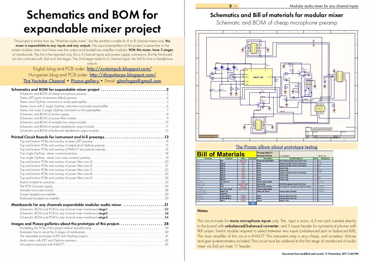
Schematics and Bill of materials for modular mixer
Schematic and BOM of cheap microphone preamp
7
This project is similar than my “Modular audio mixer”, but the another is made for 4 or 8 channel mixers only, this
mixer is expandable to any inputs and any outputs. The input preamplifiers of this project is same than in the
simple modular mixer, but I have new line output and headphone amplifier modules. With this mixer, have 3 stages
of mainboards. The first is the required only, this is 4 channel inputs and power supply connectors. But the first board
can be continued with 2nd and 3rd stages. The 2nd stage made for 2 channel inputs, the 3rd for line or headphone
outputs.
Modular audio mixer for any channel inputs
V+
Schematics and BOM for
expandable mixer project
3 -
Footprint
006E
AXIAL-0.4
AXIAL-0.4
AXIAL-0.4
AXIAL-0.4
AXIAL-0.4
AXIAL-0.4
AXIAL-0.4
AXIAL-0.4
Cap, Tantal, 1mil
DIP-8
DO-35
Elco 12 mm, 2 mil pins
HDR2X6_CEN
Jack input 6.3
Pot Mono MetalCase
Pot Mono MetalCase
RAD-0.3
Value
OPA137
100K
1K
1M
2.2K
470
47K
6.8K
8
10uF
INA217 AIP
1N4148
47uF 60V
1.6kA
47kB
100nF
Preamp-INA217
Module.PrjPcb
Quantity
2
2
2
1
2
2
1
2
1
3
1
4
3
4
1
1
1
1
34
Description
FET-Input Operational Amplifiers
Resistor
Resistor
Resistor
Resistor
Resistor
Resistor
Resistor
Resistor
Polarized Capacitor (Radial)
Instrument Amp
High Conductance Fast Diode
Polarized Capacitor (Radial)
Header, 6-Pin, Dual row
Resistor
Resistor
Capacitor
11/10/2011
Model:Footprint
DIP; 8 Leads; Row Spacing 7.62 mm; Pitch 2.54 mm
Axial Device, Thru-Hole; 2 Leads; 0.4 in Pin Spacing
Axial Device, Thru-Hole; 2 Leads; 0.4 in Pin Spacing
Resistor; 2 Leads
Resistor; 2 Leads
Axial Device, Thru-Hole; 2 Leads; 0.4 in Pin Spacing
Resistor; 2 Leads
Resistor; 2 Leads
Resistor; 2 Leads
DIP, 8-Pin, Row Spacing 7.62 mm, Pitch 2.54 mm
Diode, Axial; Body 3.8 x 1.9 mm (LxDia. max), Lead Dia. 0.53 mm (max)
Connector; Header; 6x2 Position
3 pin mono metal case pot, 2 mil
3 pin mono metal case pot, 2 mil
Capacitor; 2 Leads
16:31:13
Pins
Designator
#Column Name Error:Price
#Column Name Error:PriceH
Total
Total H
U3, U4
$0.00
0 Ft
2 R11, R15
$0.00
0 Ft
2 R4, R5
$0.00
0 Ft
2 R10
$0.00
0 Ft
2 R13, R14
$0.00
0 Ft
2 R7, R12
$0.00
0 Ft
2 R1
$0.00
0 Ft
2 R6, R9
$0.00
0 Ft
2 R8
$0.00
0 Ft
2 C10, C11, C15
$0.00
0 Ft
8 U1
$0.00
0 Ft
2 D1, D2, D3, D4
$0.00
0 Ft
2 C5, C12, C13
$0.00
0 Ft
12 P3, P4, P5, P6
$0.00
0 Ft
6 J1
$0.00
0 Ft
3 P1
$0.00
0 Ft
3 P2
$0.00
0 Ft
2 C14
$0.00
0 Ft
8
SUM: $0.00
Notes
This circuit made for mono microphone inputs only. The input is mono, 6.3 mm jack inserted directly
to the board with unbalanced/balanced converter, and 3 inputs header for symmetrical phones with
XLR output. Switch module required to select between two inputs (unbalanced jack or balanced XLR).
The main amplifier of this circuit is INA217. This instrument amp is very cheap, and noiseless. Volume
and gain potentiometers included. This circuit must be soldered to the first stage of mainboard of audio
mixer via 2x6 pin male “L” header.
Document last modified and saved: 11 November 2011 5:40 PM
0 Ft
Modular audio mixer for any channel inputs - 4
5 -
Schematics and Bill of materials for modular mixer
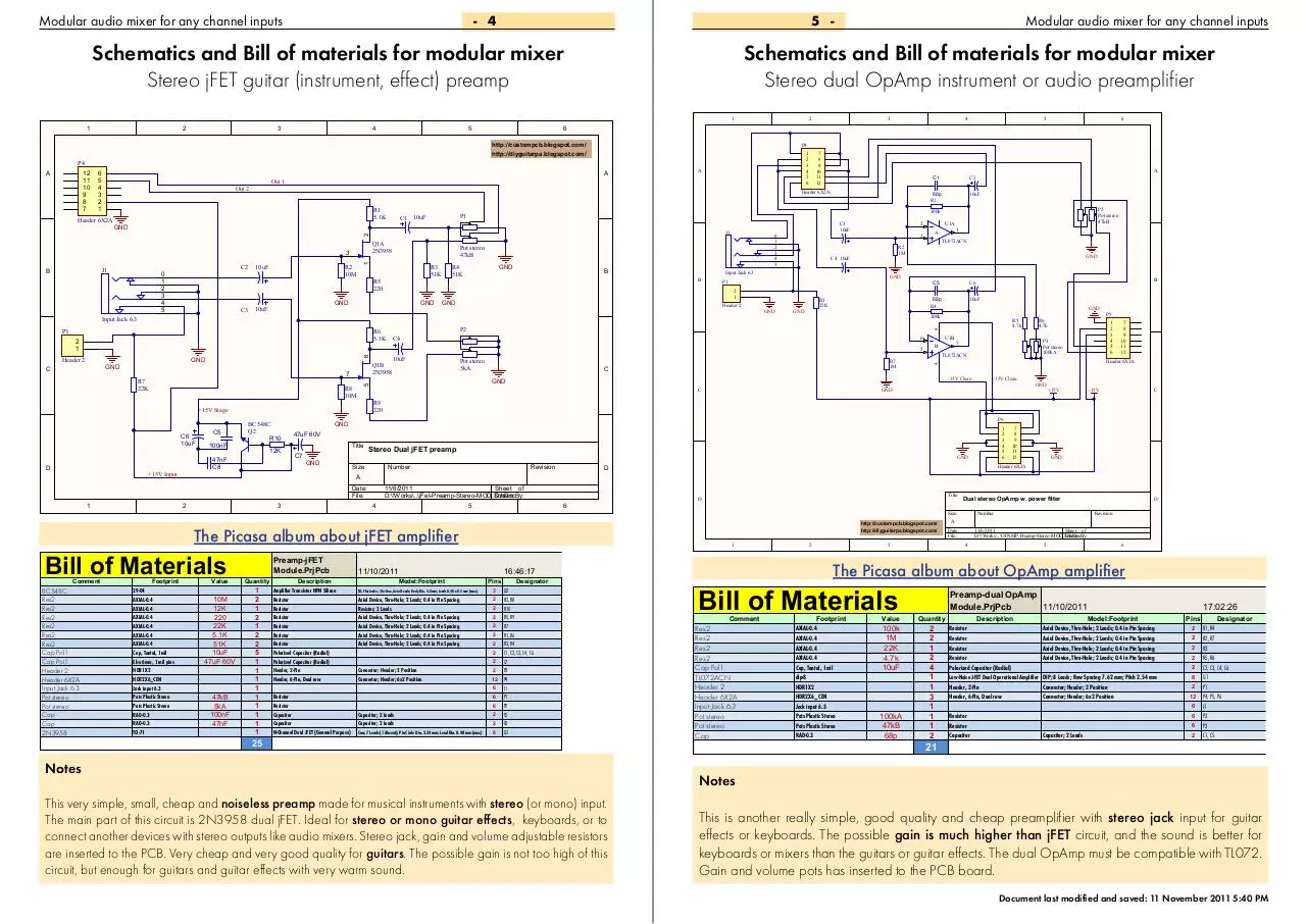
Stereo jFET guitar (instrument, effect) preamp
Schematics and Bill of materials for modular mixer
Stereo dual OpAmp instrument or audio preamplifier
1
1
2
3
4
5
2
6
5
4
3
2
1
1
2
3
4
5
6
R1
5.1K
J1
B
0
1
2
3
4
5
C3
A
10uF
R2
10M
R3
51K
R5
220
GND
10uF
GND
R4
51K
GND
B
GND
P1
GND
Header 2
GND
2
1
Q1B
2N3958
7
R7
22K
R8
10M
C6
10uF
D
100nF
BC548C
Q2
R10
12K
47nF
C8
+15V Input
8
B
1
Pot stereo
5kA
R7
1M
C
-15V Clean
C
Title
3
Bill of Materials
29-04
AXIAL-0.4
AXIAL-0.4
AXIAL-0.4
AXIAL-0.4
AXIAL-0.4
AXIAL-0.4
Cap, Tantal, 1mil
Elco 6mm, 1 mil pins
HDR1X2
HDR2X6_CEN
Jack input 6.3
Pots Plastic Stereo
Pots Plastic Stereo
RAD-0.3
RAD-0.3
TO-71
+15V
C
-15V
1
2
3
4
5
6
Stereo Dual jFET preamp
Size
GND
Number
Revision
7
8
9
10
11
12
GND
Header 6X2A
D
A
2
Footprint
GND
P6
11/6/2011
Sheet of
D:\!Works\..\jFet-Preamp-Stereo-MOD.SchDoc
Drawn By:
4
5
Value
10M
12K
220
22K
5.1K
51K
10uF
47uF 60V
47kB
5kA
100nF
47nF
Preamp-jFET
Module.PrjPcb
Quantity
1
2
1
2
1
2
2
5
1
1
1
1
1
1
1
1
1
25
Description
Amplifier Transistor NPN Silicon
Resistor
Resistor
Resistor
Resistor
Resistor
Resistor
Polarized Capacitor (Radial)
Polarized Capacitor (Radial)
Header, 2-Pin
Header, 6-Pin, Dual row
Resistor
Resistor
Capacitor
Capacitor
N-Channel Dual JFET (General Purpose)
Title
D
6
http://custompcb.blogspot.com/
http://diyguitarpa.blogspot.com/
1
11/10/2011
TO, Flat Index; 3 In-Line, Axial Leads; Body Dia. 4.8mm; Leads 0.48 x 0.5 mm (max)
Axial Device, Thru-Hole; 2 Leads; 0.4 in Pin Spacing
Resistor; 2 Leads
Axial Device, Thru-Hole; 2 Leads; 0.4 in Pin Spacing
Axial Device, Thru-Hole; 2 Leads; 0.4 in Pin Spacing
Axial Device, Thru-Hole; 2 Leads; 0.4 in Pin Spacing
Axial Device, Thru-Hole; 2 Leads; 0.4 in Pin Spacing
Connector; Header; 2 Position
Connector; Header; 6x2 Position
Capacitor; 2 Leads
Capacitor; 2 Leads
Can; 7 Leads (1 Absent); Pin Circle Dia. 2.54 mm; Lead Dia. 0.48 mm (max)
Pins
Designator
#Column Name Error:Price
#Column Name Error:PriceH
Total
Total H
3 Q2
$0.00
0 Ft
2 R2, R8
$0.00
0 Ft
2 R10
$0.00
0 Ft
2 R5, R9
$0.00
0 Ft
2 R7
$0.00
0 Ft
2 R1, R6
$0.00
0 Ft
2 R3, R4
$0.00
0 Ft
2 C1, C2, C3, C4, C6
$0.00
0 Ft
2 C7
$0.00
0 Ft
2 P3
$0.00
0 Ft
12 P4
$0.00
0 Ft
6 J1
$0.00
0 Ft
6 P1
$0.00
0 Ft
6 P2
$0.00
0 Ft
2 C5
$0.00
0 Ft
2 C8
$0.00
0 Ft
6 Q1
$0.00
0 Ft
SUM: $0.00
Notes
This very simple, small, cheap and noiseless preamp made for musical instruments with stereo (or mono) input.
The main part of this circuit is 2N3958 dual jFET. Ideal for stereo or mono guitar effects, keyboards, or to
connect another devices with stereo outputs like audio mixers. Stereo jack, gain and volume adjustable resistors
are inserted to the PCB. Very cheap and very good quality for guitars. The possible gain is not too high of this
circuit, but enough for guitars and guitar effects with very warm sound.
0 Ft
2
3
Number
D
Revision
A
Date:
File:
11/6/2011
Sheet of
D:\!Works\..\OPAMP-Preamp-Stereo-MOD.SchDoc
Drawn By:
4
5
6
The Picasa album about OpAmp amplifier
16:46:17
Model:Footprint
Dual stereo OpAmp w. power filter
Size
The Picasa album about jFET amplifier
Comment
+15V Clean
GND
GND
GND
7
8
9
10
11
12
Header 6X2A
47uF 60V
C7
P5
1
2
3
4
5
6
P3
Pot stereo
100kA
7
TL072ACN
GND
Date:
File:
BC548C
Res2
Res2
Res2
Res2
Res2
Res2
Cap Pol1
Cap Pol1
Header 2
Header 6X2A
Input Jack 6.3
Pot stereo
Pot stereo
Cap
Cap
2N3958
U1B
6
R6
4.7k
R9
220
+15V Stage
C5
10uF
R5
4.7k
4
6
GND
GND
GND
100k
C4
5
Header 2
10uF
68p
R4
5
C
B
C6
C5
R3
22K
GND
1
GND
P2
R6
5.1K
P2
Pot stereo
47kB
TL072ACN
R2
1M
C4 10uF
2
1
A
3
Input Jack 6.3
B
U1A
2
Input Jack 6.3
P3
10uF
68p
R1
C3
10uF
0
1
2
3
4
5
Pot stereo
47kB
1
3
6
100k
J1
Q1A
2N3958
5
C2
C1
P1
C1 10uF
GND
C2
7
8
9
10
11
12
Header 6X2A
2
Header 6X2A
A
A
Out 1
Out 2
4
P4
P4
12
11
10
9
8
7
3
6
http://custompcb.blogspot.com/
http://diyguitarpa.blogspot.com/
A
Modular audio mixer for any channel inputs
Bill of Materials
Comment
Res2
Res2
Res2
Res2
Cap Pol1
TL072ACN
Header 2
Header 6X2A
Input Jack 6.3
Pot stereo
Pot stereo
Cap
Footprint
AXIAL-0.4
AXIAL-0.4
AXIAL-0.4
AXIAL-0.4
Cap, Tantal, 1mil
dip-8
HDR1X2
HDR2X6_CEN
Jack input 6.3
Pots Plastic Stereo
Pots Plastic Stereo
RAD-0.3
Value
100k
1M
22K
4.7k
10uF
100kA
47kB
68p
Preamp-dual OpAmp
Module.PrjPcb
11/10/2011
Quantity
2
2
1
2
4
1
1
3
1
1
1
2
Description
Model:Footprint
Axial Device, Thru-Hole; 2 Leads; 0.4 in Pin Spacing
Axial Device, Thru-Hole; 2 Leads; 0.4 in Pin Spacing
Axial Device, Thru-Hole; 2 Leads; 0.4 in Pin Spacing
Axial Device, Thru-Hole; 2 Leads; 0.4 in Pin Spacing
Resistor
Resistor
Resistor
Resistor
Polarized Capacitor (Radial)
Low-Noise J-FET Dual Operational Amplifier DIP; 8 Leads; Row Spacing 7.62 mm; Pitch 2.54 mm
Header, 2-Pin
Connector; Header; 2 Position
Header, 6-Pin, Dual row
Connector; Header; 6x2 Position
Resistor
Resistor
Capacitor
Capacitor; 2 Leads
17:02:26
Pins
Designator
#Column Name Error
R1, R4
$0
2 R2, R7
$0
2 R3
$0
2 R5, R6
$0
2 C2, C3, C4, C6
$0
8 U1
$0
2 P1
$0
12 P4, P5, P6
$0
6 J1
$0
6 P3
$0
6 P2
$0
2 C1, C5
$0
2
21
SUM: $
Notes
This is another really simple, good quality and cheap preamplifier with stereo jack input for guitar
effects or keyboards. The possible gain is much higher than jFET circuit, and the sound is better for
keyboards or mixers than the guitars or guitar effects. The dual OpAmp must be compatible with TL072.
Gain and volume pots has inserted to the PCB board.
Document last modified and saved: 11 November 2011 5:40 PM
Modular audio mixer for any channel inputs - 6
7 -
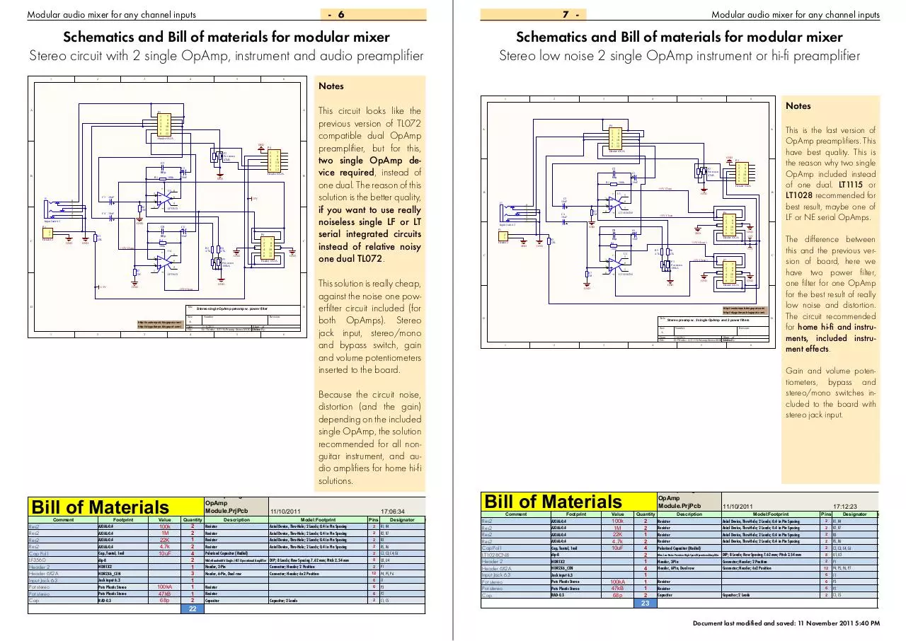
Schematics and Bill of materials for modular mixer
Stereo circuit with 2 single OpAmp, instrument and audio preamplifier
3
4
5
6
Notes
1
1
2
3
4
5
6
7
8
9
10
11
12
Header 6X2A
GND
C1
C2
68p
B
C3
0
1
2
3
4
5
C4
10uF
R2
1M
10uF
Input Jack 6.3
GND
P1
2
1
C
Header 2
1
GND
GND
6
5
LF356D
C6
P6
10uF
68p
R4
100k
7
+15V Clean
U4
2
8
GND
P3
Pot stereo
100kA
7
8
9
10
11
12
C
GND
Header 6X2A
GND
GND
-15V Clean
Title
http://custompcb.blogspot.com/
http://diyguitarpa.blogspot.com/
3
D
Stereo single OpAmp preamp w. power filter
Size
2
1
2
3
4
5
6
Number
Revision
A
Date:
File:
11/6/2011
Sheet of
D:\!Works\..\LF356-Preamp-Stereo-MOD.SchDoc
Drawn By:
4
5
6
1
2
3
4
5
6
Bill of Materials
Comment
Res2
Res2
Res2
Res2
Cap Pol1
LF356D
Header 2
Header 6X2A
Input Jack 6.3
Pot stereo
Pot stereo
Cap
Footprint
AXIAL-0.4
AXIAL-0.4
AXIAL-0.4
AXIAL-0.4
Cap, Tantal, 1mil
dip-8
HDR1X2
HDR2X6_CEN
Jack input 6.3
Pots Plastic Stereo
Pots Plastic Stereo
RAD-0.3
Value
100k
1M
22K
4.7k
10uF
100kA
47kB
68p
Quantity
2
2
1
2
4
2
1
3
1
1
1
2
22
Description
Resistor
Resistor
Resistor
Resistor
Polarized Capacitor (Radial)
Wide-Bandwidth Single J-FET Operational Amplifier
Header, 2-Pin
Header, 6-Pin, Dual row
Resistor
Resistor
Capacitor
Model:Footprint
Axial Device, Thru-Hole; 2 Leads; 0.4 in Pin Spacing
Axial Device, Thru-Hole; 2 Leads; 0.4 in Pin Spacing
Axial Device, Thru-Hole; 2 Leads; 0.4 in Pin Spacing
Axial Device, Thru-Hole; 2 Leads; 0.4 in Pin Spacing
DIP; 8 Leads; Row Spacing 7.62 mm; Pitch 2.54 mm
Connector; Header; 2 Position
Connector; Header; 6x2 Position
Capacitor; 2 Leads
Notes
A
Header 6X2A
GND
C2
68p
R1
10uF
100k
J1
Input Jack 6.3
P1
Header 2
8
GND
2
1
GND
GND
6
3
R2
1M
C4
10uF
1
LT1028CN8
8
R7
1M
R5
4.7k
-15V
+15V
R6
4.7k
C
P3
Pot stereo
100kA
6
1
-15V Clean 1
P7
GND
1
2
3
4
5
6
LT1028CN8
GND
GND
7
8
9
10
11
12
GND
Header 6X2A
http://custompcb.blogspot.com/
http://diyguitarpa.blogspot.com/
D
Title
D
Stereo preamp w. 2 single OpAmp and 2 power filters
Size
Number
Revision
A
Date:
File:
1
2
3
11/6/2011
Sheet of
D:\!Works\..\LT1115-Preamp-Stereo-MOD.SchDoc
Drawn By:
4
This is the last version of
OpAmp preamplifiers. This
have best quality. This is
the reason why two single
OpAmp included instead
of one dual. LT1115 or
LT1028 recommended for
best result, maybe one of
LF or NE serial OpAmps.
GND
+15V Clean 1
U2
5
3
7
8
9
10
11
12
Header 6X2A
100k
2
1
2
3
4
5
6
GND
10uF
68p
R4
C
P6
-15V Clean
C6
C5
R3
22K
B
GND
5
2
C3
10uF
0
1
2
3
4
5
U1
7
8
9
10
11
12
Header 6X2A
+15V Clean
B
P5
1
2
3
4
5
6
P2
Pot stereo
47kB
C1
This solution is really cheap,
against the noise one powerfilter circuit included (for
both OpAmps). Stereo
jack input, stereo/mono
and bypass switch, gain
and volume potentiometers
inserted to the board.
11/10/2011
6
7
8
9
10
11
12
5
6
The difference between
this and the previous version of board, here we
have two power filter,
one filter for one OpAmp
for the best result of really
low noise and distortion.
The circuit recommended
for home hi-fi and instruments, included instrument effects.
Gain and volume potentiometers, bypass and
stereo/mono switches included to the board with
stereo jack input.
Because the circuit noise,
distortion (and the gain)
depending on the included
single OpAmp, the solution
recommended for all nonguitar instrument, and audio amplifiers for home hi-fi
solutions.
Preamp-single
OpAmp
Module.PrjPcb
5
P4
A
LF356D
D
1
R6
4.7k
5
4
1
R7
1M
R5
4.7k
6
3
+15V
-15V
C5
R3
22K
B
GND
U3 8
3
4
J1
2
7
8
9
10
11
12
Header 6X2A
10uF
100k
7
R1
P4
1
2
3
4
5
6
P2
Pot stereo
47kB
This circuit looks like the
previous version of TL072
compatible dual OpAmp
preamplifier, but for this,
two single OpAmp device required, instead of
one dual. The reason of this
solution is the better quality,
if you want to use really
noiseless single LF or LT
serial integrated circuits
instead of relative noisy
one dual TL072.
4
7
A
P5
3
7
A
2
4
2
Schematics and Bill of materials for modular mixer
Stereo low noise 2 single OpAmp instrument or hi-fi preamplifier
4
1
Modular audio mixer for any channel inputs
Bill of Materials
17:06:34
Comment
Pins
Designator
#Column Name Error:Price
#Column Name
Total
Total H
Res2 Error:PriceH
2 R1, R4
$0.00
0 Ft
Res2
2 R2, R7
$0.00
0 Ft
Res2
2 R3
$0.00
0 Ft
Res2
2 R5, R6
$0.00
Cap Pol10 Ft
2 C2, C3, C4, C6
$0.00
0 Ft
LT1028CN8
8 U3, U4
$0.00
Header 20 Ft
2 P1
$0.00
0 Ft
Header 6X2A
12 P4, P5, P6
$0.00
Ft
Input Jack0 6.3
6 J1
$0.00
Pot stereo0 Ft
6 P3
$0.00
Pot stereo0 Ft
6 P2
$0.00
0 Ft
Cap
2 C1, C5
$0.00
0 Ft
SUM: $0.00
0 Ft
Footprint
AXIAL-0.4
AXIAL-0.4
AXIAL-0.4
AXIAL-0.4
Cap, Tantal, 1mil
dip-8
HDR1X2
HDR2X6_CEN
Jack input 6.3
Pots Plastic Stereo
Pots Plastic Stereo
RAD-0.3
Value
100k
1M
22K
4.7k
10uF
100kA
47kB
68p
Preamp-single HQ
OpAmp
Module.PrjPcb
Quantity
2
2
1
2
4
2
1
4
1
1
1
2
Description
Resistor
Resistor
Resistor
Resistor
Polarized Capacitor (Radial)
11/10/2011
Model:Footprint
Axial Device, Thru-Hole; 2 Leads; 0.4 in Pin Spacing
Axial Device, Thru-Hole; 2 Leads; 0.4 in Pin Spacing
Axial Device, Thru-Hole; 2 Leads; 0.4 in Pin Spacing
Axial Device, Thru-Hole; 2 Leads; 0.4 in Pin Spacing
Header, 2-Pin
Header, 6-Pin, Dual row
DIP; 8 Leads; Row Spacing 7.62 mm; Pitch 2.54 mm
Connector; Header; 2 Position
Connector; Header; 6x2 Position
Resistor
Resistor
Capacitor
Capacitor; 2 Leads
Ultra Low Noise Precision High-Speed Operational Amplifier
17:12:23
Pins
Designator
#Column Name Error:
R1, R4
$0.
2 R2, R7
$0.
2 R3
$0.
2 R5, R6
$0.
2 C2, C3, C4, C6
$0.
8 U1, U2
$0.
2 P1
$0.
12 P4, P5, P6, P7
$0.
6 J1
$0.
6 P3
$0.
6 P2
$0.
2 C1, C5
$0.
2
23
SUM: $0
Document last modified and saved: 11 November 2011 5:40 PM
Modular audio mixer for any channel inputs - 8
9 -
Schematics and Bill of materials for modular mixer
Schematic and BOM of power supply
1
2
3
4
A
3
5
15V AC - 1
KBL04
C6
47n
3
B
D1
+15V In
C2
10 1W
2200u
C1
2200u
6
OUT
ADJ
C4
100n
2
D2
16V Zener
C3
47u
H1
B
C10
2200u
R2
D3
16V Zener
100n
C13
-15V In
C
2
IN
ADJ
OUT
D
http://custompcb.blogspot.com/
http://diyguitarpa.blogspot.com/
C12
47u
1
2
C
3
D
BC550C
BC560C
Res2
Cap Pol1
Cap
Cap
Cap Pol1
Header 6X2A
Sheet of
Drawn By:
5
6
LM317BT
LM337BT
Res2
KBL04
16V Zener
Cap Pol1
Cap Pol1
Connector
Cap
Cap
Footprint
221A-04
221A-04
AXIAL-0.4
Bridge hor.
DIODE-0.7
Elco 12 mm, 2 mil pins
ELCO 22 MM 4 MIL
panel connector 3 input big
RAD-0.3
RAD-0.3
Value
10 1W
47u
2200u
100n
47n
PowerSupply.PrjPcb 11/10/2011
Quantity
1
1
2
1
2
2
4
2
4
4
23
Description
Pins
3-Terminal Adjustable Positive Voltage Regulator TO, Thru-Hole, Vertical, Heatsink Mounted; 3 In-Line Leads; Pitch 2.54 mm
3
3-Terminal Adjustable Negative Voltage Regulator TO, Thru-Hole, Vertical, Heatsink Mounted; 3 In-Line Leads; Pitch 2.54 mm
3
Resistor
Full Wave Diode Bridge
Zener Diode
Polarized Capacitor (Radial)
Polarized Capacitor (Radial)
2
Capacitor
Capacitor
Axial Device, Thru-Hole; 2 Leads; 0.4 in Pin Spacing
4
Diode, Thru-Hole; 2 Leads; 0.7 in Pin Spacing
2
2
2
3 pin, 3 mil connector
Radial Cap, Thru-Hole; 2 Leads; 0.3 in Pin Spacing
Radial Cap, Thru-Hole; 2 Leads; 0.3 in Pin Spacing
3
2
2
12K
C6
47nF
47uF 60V
C7
B
GND
2
Footprint
29-04
29-04
AXIAL-0.4
Cap, Tantal, 1mil
CAP, WIMA, 2MIL
CAP, WIMA, 2MIL
Elco 6mm, 1 mil pins
HDR2X6_CEN
Number
Date:
File:
10/11/2011
D:\!Works\..\PowerFilter.SchDoc
3
Value
BC550C
BC560C
12K
10uF
100nF
47nF
47uF 60V
4
Power Filter.PrjPcb
Quantity
1
1
2
2
2
2
2
1
Revision
A
Description
Transistor NPN Silicon
Transistor PNP Silicon
Resistor
Polarized Capacitor (Radial)
Capacitor
Capacitor
Polarized Capacitor (Radial)
Header, 6-Pin, Dual row
Sheet of
Drawn By:
D
5
6
11/10/2011
17:20:43
Model:Footprint
TO, Flat Index; 3 In-Line, Axial Leads; Body Dia. 4.8mm; Leads 0.48 x 0.5 mm (max)
TO, Flat Index; 3 In-Line, Axial Leads; Body Dia. 4.8mm; Leads 0.48 x 0.5 mm (max)
Resistor; 2 Leads
Connector; Header; 6x2 Position
Pins
3
Q2
3 Q1
2 R1, R2
2 C4, C5
2 C2, C3
2 C6, C8
2 C1, C7
12 P1
Designator
#Column Name Error:
$0.
$0.
$0.
$0.
$0.
$0.
$0.
$0.
SUM: $0
Notes
17:24:05
Model:Footprint
BC550C
Q2
R2
13
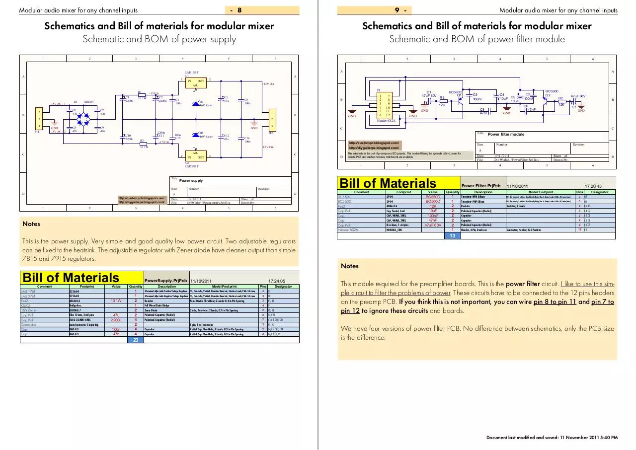
This is the power supply. Very simple and good quality low power circuit. Two adjustable regulators
can be fixed to the heatsink. The adjustable regulator with Zener diode have cleaner output than simple
7815 and 7915 regulators.
Comment
GND
C2
100nF
Power filter module
Size
This schematic is the partof preamps and EQ projects. This module filtering the symmatrical (+-) power for
circuits. PCB and another modules, mainboards are available.
Comment
Notes
Bill of Materials
C8
47nF
GND
GND
Bill of Materials
Revision
D
4
12K
C4
10uF C5
10uF
C3
100nF
C
1
A
3
BC560C
Q1
http://custompcb.blogspot.com/
http://diyguitarpa.blogspot.com/
-15V Out
10/17/2011
D:\!Works\..\Power supply.SchDoc
R1
Title
C14
100n
Number
Date:
File:
6
Header 6X2A
Power supply
Size
5
C
U2
LM337BT
Title
C1
47uF 60V
7
8
9
10
11
12
H2
1
10 1W
GND
3
GND
2200u
C11
1
2
3
4
5
6
B
C5
100n
1
C9
47n
4
A
P1
C7
47n
C8
47n
3
+15V Out
2
GND
15V AC - 2
2
A
2
1
1
1
R1
Schematics and Bill of materials for modular mixer
Schematic and BOM of power filter module
A
LM317BT
U1
IN
Modular audio mixer for any channel inputs
This module required for the preamplifier boards. This is the power filter circuit. I like to use this simple circuit to filter the problems of power. These circuits have to be connected to the 12 pins headers
on the preamp PCB. If you think this is not important, you can wire pin 8 to pin 11 and pin 7 to
pin 12 to ignore these circuits and boards.
Designator
#Column Name Error:Price
#Column Name Error:PriceH
Total
Total H
U1
$0.00
0 Ft
U2
$0.00
0 Ft
R1, R2
$0.00
0 Ft
D1
$0.00
0 Ft
D2, D3
$0.00
0 Ft
C3, C12
$0.00
0 Ft
C1, C2, C10, C11
$0.00
0 Ft
H1, H2
$0.00
0 Ft
C4, C5, C13, C14
$0.00
0 Ft
C6, C7, C8, C9
$0.00
0 Ft
SUM: $0.00
We have four versions of power filter PCB. No difference between schematics, only the PCB size
is the0 Ftdifference.
Document last modified and saved: 11 November 2011 5:40 PM
Modular audio mixer for any channel inputs - 10
11 -
Schematics and Bill of materials for modular mixer
Schematic and BOM of variable line output module
Schematics and Bill of materials for modular mixer
Schematic and BOM of simple headphone output module
1
1
2
3
4
5
Modular audio mixer for any channel inputs
2
3
4
5
6
6
R1
A
1k
R2
A
A
4
+15V clean
U1A
TL074J
2
R5
3
A
1
R1
100
U1B
TL074J
6
R6
B
5
GND
GND
1
2
3
4
5
6
GND
7
8
9
10
11
12
U1D
TL074J
13
R8
12
D
14
1k
R4
100
4
100k
GND
1
2
3
4
5
6
GND
R5
P2
Pot stereo
47k
Header 6X2A
P1
GND
Header 6X2A
21
GND
+15V
GND 3
18
-15V
1
20
+15V
J1
C
0
1
2
3
Pot stereo
47kB
-15V
Jack input 3.2
J2
GND
J4
0
1
2
3
4
5
Bill of Materials
Title
C2
100n
B
C1
100uF 25V
C3
100n
2
Size
Footprint
AXIAL-0.4
AXIAL-0.4
HDR2X6_CEN
J014
JACK INPUT 3.2
Jack input 6.3
Pots Plastic Stereo
Stereo RCA input
Value
100
100k
47k
Date:
outputsFile:
Mixer
Stage3.PrjPcb
Quantity
4
4
2
1
1
2
1
1
Number
D
C4
100uF 25V
11/11/2011
D:\!Works\..\Mixer outputs.SchDoc
4
Description
Resistor
Resistor
Header, 6-Pin, Dual row
Low-Noise JFET-Input Operational Amplifier
Resistor
11/10/2011
http://custompcb.blogspot.com/
http://diyguitarpa.blogspot.com/
Sheet of
Drawn By:
5
Model:Footprint
Resistor; 2 Leads
Resistor; 2 Leads
Connector; Header; 6x2 Position
DIP; 14 Leads; Row Spacing 7.62 mm; Pitch 2.54 mm
6
17:50:29
Headphone amp for modular Mixer mainboard stage 3
Size
Revision
1
Designator
#Column Name Error:Price
#Column Name Error:PriceH
Total
Total H
2 R1, R2, R3, R4
$0.00
0 Ft
2 R5, R6, R7, R8
$0.00
0 Ft
12 P1, P3
$0.00
0 Ft
14 U1
$0.00
0 Ft
Comment
5 J1
$0.00
0 Ft
Res2
6 J3, J4
$0.00
0 Ft
Res2
6 P2
$0.00
0 Ft
Cap
3 J2
$0.00
0 Ft
Number
D
Revision
A
Date:
File:
2
11/11/2011
D:\!Works\..\HF-TPA6120.SchDoc
3
Sheet of
Drawn By:
4
5
6
Pins
Notes
This is the PCB for line level mixer outputs with volume level stereo potentiometer. Have to be connected to the stage no.3 of
mixer mainboard. This stage of mixer have balance adjustment feature if required. With this board, you have two line outputs
with variations:
2 pcs 6.3mm jack
1 pcs 6.3mm jack and 1 pcs 3.2mm jack
1 pcs 6.3mm jack and 1 pcs stereo RCA
1 pcs 3.2mm jack and 1 pcs stereo RCA
D
A
GND
3
Title
Output module for Mixer mainboard stage 3
16
•
•
•
•
P2
Header 6X2A
http://custompcb.blogspot.com/
http://diyguitarpa.blogspot.com/
Input Jack 6.3
GND
Res2
Res2
Header 6X2A
TL074J
Jack input 3.2
Input Jack 6.3
Pot stereo
Stereo RCA
6
7
8
9
10
11
12
13
14
15
GND
0
1
2
3
4
5
Input Jack 6.3
Comment
LVCCRVCC-
19
C
1
2
3
4
5
6
GND
Stereo RCA
1
LVCC+
RVCC+
Input Jack 6.3
TPA6120
7
8
9
10
11
12
2
D
GND
10
1
0
J3
NC
NC
NC
NC
NC
NC
NC
NC
NC
NC
R4
2
J1
GND GND
C
C
5
ROUT
RIN-
1k
B
B
RIN+
16
10
LOUT
LIN-
17
R6
GND
LIN+
5
1k
7
8
9
10
11
12
5
4
3
2
1
0
R3
U1
P1
GND
P3
C
10
8
R3
100
100k
-15v clean
B
U1C
TL074J
9
R7
100k
11
100k
7
R2
100
A
GND
Bill of Materials
SUM: $0.00
Cap Pol1
0 Ft
Header 6X2A
Input Jack 6.3
Pot stereo
TPA6120
Footprint
AXIAL-0.4
AXIAL-0.4
CAP, 2 and 3 MIL
Elco 6mm, 1 mil pins
HDR2X6_CEN
Jack input 6.3
Pots Plastic Stereo
Powerpad 20
Value
10
1k
100n
100uF 25V
47kB
TPA6120 Simple
Mod.PrjPcb
Quantity
2
4
2
2
1
1
1
1
11/10/2011
Description
Resistor
Resistor
Capacitor
Polarized Capacitor (Radial)
Header, 6-Pin, Dual row
Resistor
17:52:41
Model:Footprint
Resistor; 2 Leads
Resistor; 2 Leads
Connector; Header; 6x2 Position
Pins
Designator
#Column Name Error:
R3, R4
$0.
2 R1, R2, R5, R6
$0.
2 C2, C3
$0.
2 C1, C4
$0.
12 P2
$0.
6 J1
$0.
6 P1
$0.
21 U1
$0.
2
14
SUM: $0
Notes
This is the circuit for headphone output for mixer with volume level stereo potentiometer. Have to be connected to the stage
no.3 of mixer mainboard. This stage of mixer have balance adjustment feature if required. This board contains SMD circuit.
TPA6120 is the one of the best class-D headphone amplifier with 120dB dynamics. This is the smallest, cheapest, and simplest
application of this module.
Document last modified and saved: 11 November 2011 5:40 PM
Modular audio mixer for any channel inputs - 12
13 -
Modular audio mixer for any channel inputs
Schematics and Bill of materials for modular mixer
Schematic and BOM of balanced headphone output module
4
6
2
5
C7
100p
4
R11
4.7k
22uF 25V
U2B
NE5532AP
7
10k
R9
100k
6
5
R12
4.7k
GND
5
U3B
NE5532AP
R1
22uF 25V
C8
100p
1k
R2
R10
100k
7
2
GND
U1
R17
150
B
C9
1k R13
GND
1
R19 22uF 25V
100k
2
C10
R20 22uF 25V
100k
GND
1
2
NE5532AP
P1
C11
100p
GND
GND 3
18
-15V
1
20
GND
LOUT
ROUT
NC
NC
NC
NC
NC
NC
NC
NC
NC
NC
GND
LVCC+
RVCC+
LVCCRVCC-
Pot stereo
47kB
2
19
6
7
8
9
10
11
12
13
14
15
R4
10
R3
10
GND
Header 6X2A
GND
GND
1
2
3
4
5
6
Printed Circuit
J1
Input Jack 6.3
C
P4
7
8
9
10
11
12
B
TPA6120
GND GND
7
8
9
10
11
12
Header 6X2A
7
8
9
10
11
12
1
2
3
4
5
6
C12
100p
+15V
P2
Header 6X2A
1
2
3
4
5
6
P3
RIN-
21
GND
C
RIN+
16
3
1
GND
LIN-
17
1k R16
U3A
R18
150
3
1
LIN+
5
1k R14
1k R15
U2A
NE5532AP
A
1k
4
GND
6
C6
R7
8
8
10k
A
3
0
1
2
3
4
5
2
C5
R5
4
1
C2
100n
C3
100n
C1
100uF 25V
C4
100uF 25V
GND
GND
Boards for
Title
Balanced headphone amp for modular Mixer mainboard stage 3
D
Size
http://custompcb.blogspot.com/
http://diyguitarpa.blogspot.com/
1
2
3
Bill of Materials
Comment
Res2
Res2
Res2
Res2
Res2
Res2
Cap
Cap
Cap Pol1
NE5532AP
Cap Pol1
Header 6X2A
Input Jack 6.3
Pot stereo
TPA6120
Footprint
AXIAL-0.4
AXIAL-0.4
AXIAL-0.4
AXIAL-0.4
AXIAL-0.4
AXIAL-0.4
CAP, 2 and 3 MIL
CAP, Ceramic, 1MIL
Cap, Tantal, 1mil
dip-8
Elco 6mm, 1 mil pins
HDR2X6_CEN
Jack input 6.3
Pots Plastic Stereo
Powerpad 20
Value
10
100k
10k
150
1k
4.7k
100n
100p
22uF 25V
100uF 25V
47kB
Date:
File:
Quantity
5
Resistor
D
6
11/10/2011
Description
Resistor
Resistor
Resistor
Resistor
Resistor
Resistor
Capacitor
Capacitor
Polarized Capacitor (Radial)
Dual Low-Noise Operational Amplifier
Polarized Capacitor (Radial)
Header, 6-Pin, Dual row
Revision
11/11/2011
Sheet of
D:\!Works\..\HF-TPA6120 Balanced.SchDocDrawn By:
4
TPA6120 Balanced
Mod.PrjPcb
2
4
2
2
6
2
2
4
4
2
2
3
1
1
1
Number
A
17:54:20
Model:Footprint
Resistor; 2 Leads
Resistor; 2 Leads
Resistor; 2 Leads
Resistor; 2 Leads
Resistor; 2 Leads
Resistor; 2 Leads
DIP; 8 Leads; Row Spacing 7.62 mm; Pitch 2.54 mm
Connector; Header; 6x2 Position
Pins
Designator
#Column Name Error:Price
#Column Name Error:PriceH
Total
Total H
R3, R4
$0.00
0 Ft
2 R9, R10, R19, R20
$0.00
0 Ft
2 R5, R7
$0.00
0 Ft
2 R17, R18
$0.00
0 Ft
2 R1, R2, R13, R14, R15, R16
$0.00
0 Ft
2 R11, R12
$0.00
0 Ft
2 C2, C3
$0.00
0 Ft
2 C7, C8, C11, C12
$0.00
0 Ft
2 C5, C6, C9, C10
$0.00
0 Ft
8 U2, U3
$0.00
0 Ft
2 C1, C4
$0.00
0 Ft
12 P2, P3, P4
$0.00
0 Ft
6 J1
$0.00
0 Ft
6 P1
$0.00
0 Ft
21 U1
$0.00
0 Ft
2
38
SUM: $0.00
instrument and hi-fi
preamps
0 Ft
Notes
This is the circuit for headphone output for mixer with volume level stereo potentiometer. Have to be connected to the stage
no.3 of mixer mainboard. This stage of mixer have balance adjustment feature if required. This board contains SMD circuit.
TPA6120 is the one of the best class-D headphone amplifier with 120dB dynamics. This module contains unbalanced/balanced converter for better result. If this feature not required, use the previous version of this schematic.
Document last modified and saved: 11 November 2011 5:40 PM
Modular audio mixer for any channel inputs - 14
15 -
PCB for the modular audio mixer
Top and bottom PCBs and overlay of stereo jFET preamp
Modular audio mixer for any channel inputs
PCB for the modular audio mixer
Top and bottom PCBs and overlay of simple dual OpAmp preamp
BOTTOM LAYER
TOP LAYER
PCB TOP OVERLAY
TOP OVERLAY ON TOP LAYER
P1
Q1
R3
7
R1
3
P2
R8
R1
C3
C4
C1
C2
C8
P3
C2
R6 R7 C6
Q2
C5
R6 R7 C6
C2
C2
R10R2
C4
C4
J1
R4 R3
R4 R3
J1
J1
3
1
J1
P1
P1
12
6
P4
7
1
P3
7
1
12
6
P4
C1
C5
P3
R10R2
C4
C6
C6
Q2
C3
3
1
C7
C5
C8
C7
C5
R9
R7
R1 R5 C1
R9
R7
R6
P2
U1
P3
R6
12
6
R4
R1 R5 C1
U1
P5
7
1
R5
R2
R8
5
1
C3
12
6
R3
OVERLAY ON TOP LAYER
P2
3
P2
R4
PCB OVERLAY
P5
7
1
P1
Q1
R2
BOTTOM LAYER
5
1
R5
C3
7
TOP LAYER
Document last modified and saved: 11 November 2011 5:40 PM
Modular audio mixer for any channel inputs - 16
17 -
Modular audio mixer for any channel inputs
PCB for the modular audio mixer
Top and bottom PCBs and overlay of INA217 microphone preamp
R8
P1
R1
J1
C10
U1
R9
C5
C15
R13
R14
R12
R10
R11
C13
P2
C12
PCB TOP OVERLAY
7
1
TOP LAYER
P4
U2
C14
R7
R6
R5
D4
D3
R15
D2
D1
R4
U3
C11
R8
P1
R1
J1
C10
U1
R9
C5
C15
R13
R14
R12
C13
P2
R10
R11
7
1
12
6
P4
U2
C14
R7
R6
R5
D4
D3
R15
D2
D1
R4
C11
U3
TOP OVERLAY ON TOP LAYER
C12
12
6
BOTTOM LAYER
Document last modified and saved: 11 November 2011 5:40 PM
Download Expandable-Modular-Mixer-public-doc
Expandable-Modular-Mixer-public-doc.pdf (PDF, 6.57 MB)
Download PDF
Share this file on social networks
Link to this page
Permanent link
Use the permanent link to the download page to share your document on Facebook, Twitter, LinkedIn, or directly with a contact by e-Mail, Messenger, Whatsapp, Line..
Short link
Use the short link to share your document on Twitter or by text message (SMS)
HTML Code
Copy the following HTML code to share your document on a Website or Blog
QR Code to this page

This file has been shared publicly by a user of PDF Archive.
Document ID: 0000035048.