fuel carb (PDF)
File information
Title: 0908-04A
Author: Ken
This PDF 1.2 document has been generated by QuarkXPressª: PSPrinter 8.3.1 / Acrobat Distiller 3.01 for Power Macintosh, and has been sent on pdf-archive.com on 07/01/2012 at 22:29, from IP address 78.40.x.x.
The current document download page has been viewed 4682 times.
File size: 839.53 KB (22 pages).
Privacy: public file


File preview
4A•1
Chapter 4 Part A:
Fuel and exhaust systems - carburettor models
Contents
Air cleaner element - renewal . . . . . . . . . . . . . . . . . . . . . . . . . . . . . . 2
Air cleaner - removal and refitting . . . . . . . . . . . . . . . . . . . . . . . . . . . 3
Accelerator cable - removal and refitting . . . . . . . . . . . . . . . . . . . . . 23
Air intake heating system - operation and maintenance . . . . . . . . . . 4
Carburettors - idle speed and mixture adjustment . . . . . . . . . . . . . . 13
Carburettors - general information . . . . . . . . . . . . . . . . . . . . . . . . . . 11
Carburettors - general maintenance . . . . . . . . . . . . . . . . . . . . . . . . . 12
Carburettors - removal and refitting . . . . . . . . . . . . . . . . . . . . . . . . . 14
Choke cable - removal and refitting . . . . . . . . . . . . . . . . . . . . . . . . . 24
Exhaust system - maintenance, removal and refitting . . . . . . . . . . . 26
Fuel level transmitter - removal and refitting . . . . . . . . . . . . . . . . . . . 9
Fuel pump - cleaning . . . . . . . . . . . . . . . . . . . . . . . . . . . . . . . . . . . . . 6
Fuel pump - removal, overhaul and refitting . . . . . . . . . . . . . . . . . . . 7
Fuel pump - testing . . . . . . . . . . . . . . . . . . . . . . . . . . . . . . . . . . . . . . 5
Fuel tank - removal, inspection and refitting . . . . . . . . . . . . . . . . . . . 10
General information and precautions . . . . . . . . . . . . . . . . . . . . . . . . 1
Inlet and exhaust manifolds - removal and refitting . . . . . . . . . . . . . 25
In-line fuel filter (BX 16 RE) - renewal . . . . . . . . . . . . . . . . . . . . . . . . 8
Solex carburettor 34 PBISA 17 - adjustment . . . . . . . . . . . . . . . . . . 16
Solex carburettors 32-34 Z1 and 34-34 Z1 - adjustment . . . . . . . . . 19
Solex carburettors 30-30 Z2 CIT 329 and 32-34 Z2 CIT 348 adjustment . . . . . . . . . . . . . . . . . . . . . . . . . . . . . . . . . . . . . . . . . . . 17
Solex carburettors 32-34 Z1 CIT 319, W 319 and 34-34 Z1 381 adjustment . . . . . . . . . . . . . . . . . . . . . . . . . . . . . . . . . . . . . . . . . . . 18
Solex carburettors - overhaul . . . . . . . . . . . . . . . . . . . . . . . . . . . . . . 15
Weber carburettors - adjustment . . . . . . . . . . . . . . . . . . . . . . . . . . . 21
Weber carburettors - overhaul . . . . . . . . . . . . . . . . . . . . . . . . . . . . . . 20
Weber carburettor 36 TLP - overhaul and adjustment . . . . . . . . . . . 22
4A
Degrees of difficulty
Easy, suitable for
novice with little
experience
1
Fairly easy, suitable
for beginner with
some experience
2
Fairly difficult,
suitable for competent
DIY mechanic
3
Difficult, suitable for
experienced DIY
mechanic
4
Very difficult,
suitable for expert DIY
or professional
Specifications
For engine to model applications refer to Chapter 2
Air cleaner
Type . . . . . . . . . . . . . . . . . . . . . . . . . . . . . . . . . . . . . . . . . . . . . . . . . . . .
Element:
BX 14 . . . . . . . . . . . . . . . . . . . . . . . . . . . . . . . . . . . . . . . . . . . . . . . . .
BX 14 (Aug 1988 to Sept 1991) . . . . . . . . . . . . . . . . . . . . . . . . . . . . .
BX 14 (Sept 1991 on) . . . . . . . . . . . . . . . . . . . . . . . . . . . . . . . . . . . . .
BX 16 (pre June 1987) . . . . . . . . . . . . . . . . . . . . . . . . . . . . . . . . . . . .
BX 16 (Sept 1988 to 1991) . . . . . . . . . . . . . . . . . . . . . . . . . . . . . . . . .
BX 19 (pre June 1987) . . . . . . . . . . . . . . . . . . . . . . . . . . . . . . . . . . . .
BX 19 (from July 1987) . . . . . . . . . . . . . . . . . . . . . . . . . . . . . . . . . . . .
BX 19 (1991 on) . . . . . . . . . . . . . . . . . . . . . . . . . . . . . . . . . . . . . . . . .
Dry type with replaceable cartridge. Manual or automatic air
temperature controlled inlet system
Champion V402
Champion V401
Champion V438
Champion W117
Champion U543
Champion W117
Champion U543
Champion U543
Fuel filter
Type . . . . . . . . . . . . . . . . . . . . . . . . . . . . . . . . . . . . . . . . . . . . . . . . . . . .
Champion L101
Fuel pump
Type . . . . . . . . . . . . . . . . . . . . . . . . . . . . . . . . . . . . . . . . . . . . . . . . . . . .
Mechanical diaphragm, driven by eccentric on camshaft
5
4A•2 Fuel and exhaust systems - carburettor models
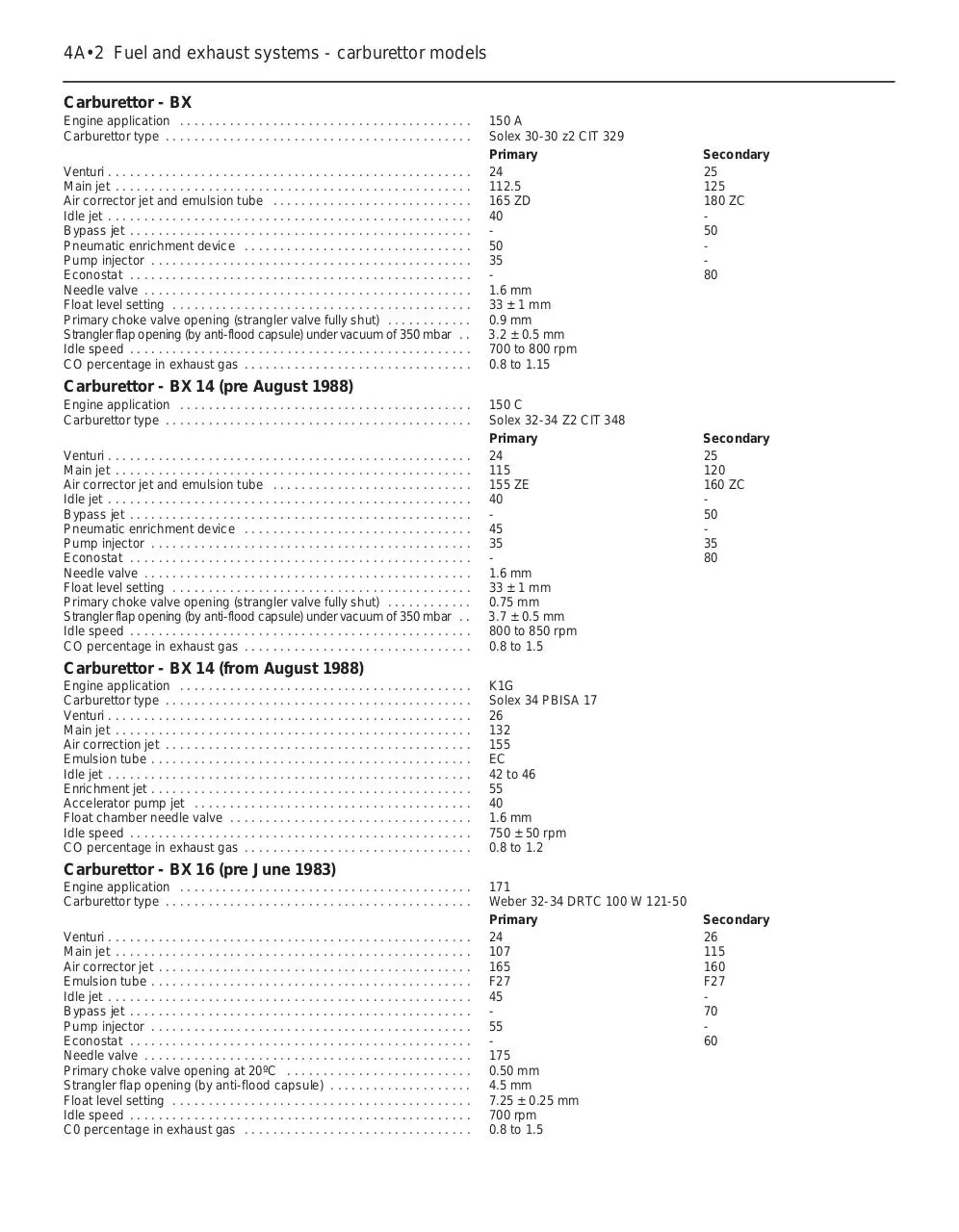
Carburettor - BX
Engine application . . . . . . . . . . . . . . . . . . . . . . . . . . . . . . . . . . . . . . . . .
Carburettor type . . . . . . . . . . . . . . . . . . . . . . . . . . . . . . . . . . . . . . . . . . .
Venturi . . . . . . . . . . . . . . . . . . . . . . . . . . . . . . . . . . . . . . . . . . . . . . . . . . .
Main jet . . . . . . . . . . . . . . . . . . . . . . . . . . . . . . . . . . . . . . . . . . . . . . . . . .
Air corrector jet and emulsion tube . . . . . . . . . . . . . . . . . . . . . . . . . . . .
Idle jet . . . . . . . . . . . . . . . . . . . . . . . . . . . . . . . . . . . . . . . . . . . . . . . . . . .
Bypass jet . . . . . . . . . . . . . . . . . . . . . . . . . . . . . . . . . . . . . . . . . . . . . . . .
Pneumatic enrichment device . . . . . . . . . . . . . . . . . . . . . . . . . . . . . . . .
Pump injector . . . . . . . . . . . . . . . . . . . . . . . . . . . . . . . . . . . . . . . . . . . . .
Econostat . . . . . . . . . . . . . . . . . . . . . . . . . . . . . . . . . . . . . . . . . . . . . . . .
Needle valve . . . . . . . . . . . . . . . . . . . . . . . . . . . . . . . . . . . . . . . . . . . . . .
Float level setting . . . . . . . . . . . . . . . . . . . . . . . . . . . . . . . . . . . . . . . . . .
Primary choke valve opening (strangler valve fully shut) . . . . . . . . . . . .
Strangler flap opening (by anti-flood capsule) under vacuum of 350 mbar . .
Idle speed . . . . . . . . . . . . . . . . . . . . . . . . . . . . . . . . . . . . . . . . . . . . . . . .
CO percentage in exhaust gas . . . . . . . . . . . . . . . . . . . . . . . . . . . . . . . .
150 A
Solex 30-30 z2 CIT 329
Primary
24
112.5
165 ZD
40
50
35
1.6 mm
33 ± 1 mm
0.9 mm
3.2 ± 0.5 mm
700 to 800 rpm
0.8 to 1.15
Secondary
25
125
180 ZC
50
80
Carburettor - BX 14 (pre August 1988)
Engine application . . . . . . . . . . . . . . . . . . . . . . . . . . . . . . . . . . . . . . . . .
Carburettor type . . . . . . . . . . . . . . . . . . . . . . . . . . . . . . . . . . . . . . . . . . .
Venturi . . . . . . . . . . . . . . . . . . . . . . . . . . . . . . . . . . . . . . . . . . . . . . . . . . .
Main jet . . . . . . . . . . . . . . . . . . . . . . . . . . . . . . . . . . . . . . . . . . . . . . . . . .
Air corrector jet and emulsion tube . . . . . . . . . . . . . . . . . . . . . . . . . . . .
Idle jet . . . . . . . . . . . . . . . . . . . . . . . . . . . . . . . . . . . . . . . . . . . . . . . . . . .
Bypass jet . . . . . . . . . . . . . . . . . . . . . . . . . . . . . . . . . . . . . . . . . . . . . . . .
Pneumatic enrichment device . . . . . . . . . . . . . . . . . . . . . . . . . . . . . . . .
Pump injector . . . . . . . . . . . . . . . . . . . . . . . . . . . . . . . . . . . . . . . . . . . . .
Econostat . . . . . . . . . . . . . . . . . . . . . . . . . . . . . . . . . . . . . . . . . . . . . . . .
Needle valve . . . . . . . . . . . . . . . . . . . . . . . . . . . . . . . . . . . . . . . . . . . . . .
Float level setting . . . . . . . . . . . . . . . . . . . . . . . . . . . . . . . . . . . . . . . . . .
Primary choke valve opening (strangler valve fully shut) . . . . . . . . . . . .
Strangler flap opening (by anti-flood capsule) under vacuum of 350 mbar . .
Idle speed . . . . . . . . . . . . . . . . . . . . . . . . . . . . . . . . . . . . . . . . . . . . . . . .
CO percentage in exhaust gas . . . . . . . . . . . . . . . . . . . . . . . . . . . . . . . .
150 C
Solex 32-34 Z2 CIT 348
Primary
24
115
155 ZE
40
45
35
1.6 mm
33 ± 1 mm
0.75 mm
3.7 ± 0.5 mm
800 to 850 rpm
0.8 to 1.5
Secondary
25
120
160 ZC
50
35
80
Carburettor - BX 14 (from August 1988)
Engine application . . . . . . . . . . . . . . . . . . . . . . . . . . . . . . . . . . . . . . . . .
Carburettor type . . . . . . . . . . . . . . . . . . . . . . . . . . . . . . . . . . . . . . . . . . .
Venturi . . . . . . . . . . . . . . . . . . . . . . . . . . . . . . . . . . . . . . . . . . . . . . . . . . .
Main jet . . . . . . . . . . . . . . . . . . . . . . . . . . . . . . . . . . . . . . . . . . . . . . . . . .
Air correction jet . . . . . . . . . . . . . . . . . . . . . . . . . . . . . . . . . . . . . . . . . . .
Emulsion tube . . . . . . . . . . . . . . . . . . . . . . . . . . . . . . . . . . . . . . . . . . . . .
Idle jet . . . . . . . . . . . . . . . . . . . . . . . . . . . . . . . . . . . . . . . . . . . . . . . . . . .
Enrichment jet . . . . . . . . . . . . . . . . . . . . . . . . . . . . . . . . . . . . . . . . . . . . .
Accelerator pump jet . . . . . . . . . . . . . . . . . . . . . . . . . . . . . . . . . . . . . . .
Float chamber needle valve . . . . . . . . . . . . . . . . . . . . . . . . . . . . . . . . . .
Idle speed . . . . . . . . . . . . . . . . . . . . . . . . . . . . . . . . . . . . . . . . . . . . . . . .
CO percentage in exhaust gas . . . . . . . . . . . . . . . . . . . . . . . . . . . . . . . .
K1G
Solex 34 PBISA 17
26
132
155
EC
42 to 46
55
40
1.6 mm
750 ± 50 rpm
0.8 to 1.2
Carburettor - BX 16 (pre June 1983)
Engine application . . . . . . . . . . . . . . . . . . . . . . . . . . . . . . . . . . . . . . . . .
Carburettor type . . . . . . . . . . . . . . . . . . . . . . . . . . . . . . . . . . . . . . . . . . .
Venturi . . . . . . . . . . . . . . . . . . . . . . . . . . . . . . . . . . . . . . . . . . . . . . . . . . .
Main jet . . . . . . . . . . . . . . . . . . . . . . . . . . . . . . . . . . . . . . . . . . . . . . . . . .
Air corrector jet . . . . . . . . . . . . . . . . . . . . . . . . . . . . . . . . . . . . . . . . . . . .
Emulsion tube . . . . . . . . . . . . . . . . . . . . . . . . . . . . . . . . . . . . . . . . . . . . .
Idle jet . . . . . . . . . . . . . . . . . . . . . . . . . . . . . . . . . . . . . . . . . . . . . . . . . . .
Bypass jet . . . . . . . . . . . . . . . . . . . . . . . . . . . . . . . . . . . . . . . . . . . . . . . .
Pump injector . . . . . . . . . . . . . . . . . . . . . . . . . . . . . . . . . . . . . . . . . . . . .
Econostat . . . . . . . . . . . . . . . . . . . . . . . . . . . . . . . . . . . . . . . . . . . . . . . .
Needle valve . . . . . . . . . . . . . . . . . . . . . . . . . . . . . . . . . . . . . . . . . . . . . .
Primary choke valve opening at 20ºC . . . . . . . . . . . . . . . . . . . . . . . . . .
Strangler flap opening (by anti-flood capsule) . . . . . . . . . . . . . . . . . . . .
Float level setting . . . . . . . . . . . . . . . . . . . . . . . . . . . . . . . . . . . . . . . . . .
Idle speed . . . . . . . . . . . . . . . . . . . . . . . . . . . . . . . . . . . . . . . . . . . . . . . .
C0 percentage in exhaust gas . . . . . . . . . . . . . . . . . . . . . . . . . . . . . . . .
171
Weber 32-34 DRTC 100 W 121-50
Primary
24
107
165
F27
45
55
175
0.50 mm
4.5 mm
7.25 ± 0.25 mm
700 rpm
0.8 to 1.5
Secondary
26
115
160
F27
70
60
Fuel and exhaust systems - carburettor models 4A•3
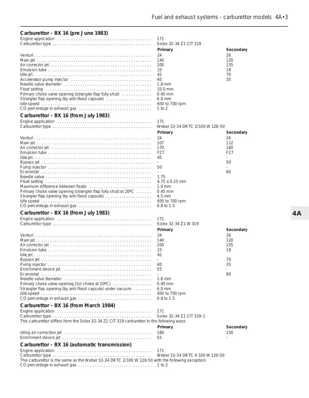
Carburettor - BX 16 (pre June 1983)
Engine application . . . . . . . . . . . . . . . . . . . . . . . . . . . . . . . . . . . . . . . . .
Carburettor type . . . . . . . . . . . . . . . . . . . . . . . . . . . . . . . . . . . . . . . . . . .
Venturi . . . . . . . . . . . . . . . . . . . . . . . . . . . . . . . . . . . . . . . . . . . . . . . . . . .
Main jet . . . . . . . . . . . . . . . . . . . . . . . . . . . . . . . . . . . . . . . . . . . . . . . . . .
Air corrector jet . . . . . . . . . . . . . . . . . . . . . . . . . . . . . . . . . . . . . . . . . . . .
Emulsion tube . . . . . . . . . . . . . . . . . . . . . . . . . . . . . . . . . . . . . . . . . . . . .
Idle jet . . . . . . . . . . . . . . . . . . . . . . . . . . . . . . . . . . . . . . . . . . . . . . . . . . .
Accelerator pump injector . . . . . . . . . . . . . . . . . . . . . . . . . . . . . . . . . . .
Needle valve diameter . . . . . . . . . . . . . . . . . . . . . . . . . . . . . . . . . . . . . .
Float setting . . . . . . . . . . . . . . . . . . . . . . . . . . . . . . . . . . . . . . . . . . . . . .
Primary choke valve opening (strangler flap fully shut) . . . . . . . . . . . . .
Strangler flap opening (by anti-flood capsule) . . . . . . . . . . . . . . . . . . . .
Idle speed . . . . . . . . . . . . . . . . . . . . . . . . . . . . . . . . . . . . . . . . . . . . . . . .
CO percentage in exhaust gas . . . . . . . . . . . . . . . . . . . . . . . . . . . . . . . .
171
Solex 32-34 Z1 CIT 319
Primary
24
140
200
23
42
40
1.8 mm
33.0 mm
0.45 mm
6.0 mm
650 to 700 rpm
1 to 2
Secondary
26
120
155
18
70
35
Carburettor - BX 16 (from July 1983)
Engine application . . . . . . . . . . . . . . . . . . . . . . . . . . . . . . . . . . . . . . . . .
Carburettor type . . . . . . . . . . . . . . . . . . . . . . . . . . . . . . . . . . . . . . . . . . .
Venturi . . . . . . . . . . . . . . . . . . . . . . . . . . . . . . . . . . . . . . . . . . . . . . . . . . .
Main jet . . . . . . . . . . . . . . . . . . . . . . . . . . . . . . . . . . . . . . . . . . . . . . . . . .
Air corrector jet . . . . . . . . . . . . . . . . . . . . . . . . . . . . . . . . . . . . . . . . . . . .
Emulsion tube . . . . . . . . . . . . . . . . . . . . . . . . . . . . . . . . . . . . . . . . . . . . .
Idle jet . . . . . . . . . . . . . . . . . . . . . . . . . . . . . . . . . . . . . . . . . . . . . . . . . . .
Bypass jet . . . . . . . . . . . . . . . . . . . . . . . . . . . . . . . . . . . . . . . . . . . . . . . .
Pump injector . . . . . . . . . . . . . . . . . . . . . . . . . . . . . . . . . . . . . . . . . . . . .
Econostat . . . . . . . . . . . . . . . . . . . . . . . . . . . . . . . . . . . . . . . . . . . . . . . .
Needle valve . . . . . . . . . . . . . . . . . . . . . . . . . . . . . . . . . . . . . . . . . . . . . .
Float setting . . . . . . . . . . . . . . . . . . . . . . . . . . . . . . . . . . . . . . . . . . . . . .
Maximum difference between floats . . . . . . . . . . . . . . . . . . . . . . . . . . .
Primary choke valve opening (strangler flap fully shut) at 20ºC . . . . . . .
Strangler flap opening (by anti-flood capsule) . . . . . . . . . . . . . . . . . . . .
Idle speed . . . . . . . . . . . . . . . . . . . . . . . . . . . . . . . . . . . . . . . . . . . . . . . .
CO percentage in exhaust gas . . . . . . . . . . . . . . . . . . . . . . . . . . . . . . . .
171
Weber 32-34 DRTC 2/100 W 128-50
Primary
24
107
170
F27
45
50
1.75
6.75 ± 0.25 mm
1.0 mm
0.45 mm
4.5 mm
650 to 700 rpm
0.8 to 1.5
Secondary
26
112
160
F27
50
60
Carburettor - BX 16 (from July 1983)
Engine application . . . . . . . . . . . . . . . . . . . . . . . . . . . . . . . . . . . . . . . . .
Carburettor type . . . . . . . . . . . . . . . . . . . . . . . . . . . . . . . . . . . . . . . . . . .
Venturi . . . . . . . . . . . . . . . . . . . . . . . . . . . . . . . . . . . . . . . . . . . . . . . . . . .
Main jet . . . . . . . . . . . . . . . . . . . . . . . . . . . . . . . . . . . . . . . . . . . . . . . . . .
Air corrector jet . . . . . . . . . . . . . . . . . . . . . . . . . . . . . . . . . . . . . . . . . . . .
Emulsion tube . . . . . . . . . . . . . . . . . . . . . . . . . . . . . . . . . . . . . . . . . . . . .
Idle jet . . . . . . . . . . . . . . . . . . . . . . . . . . . . . . . . . . . . . . . . . . . . . . . . . . .
Bypass jet . . . . . . . . . . . . . . . . . . . . . . . . . . . . . . . . . . . . . . . . . . . . . . . .
Pump injector . . . . . . . . . . . . . . . . . . . . . . . . . . . . . . . . . . . . . . . . . . . . .
Enrichment device jet . . . . . . . . . . . . . . . . . . . . . . . . . . . . . . . . . . . . . . .
Econostat . . . . . . . . . . . . . . . . . . . . . . . . . . . . . . . . . . . . . . . . . . . . . . . .
Needle valve diameter . . . . . . . . . . . . . . . . . . . . . . . . . . . . . . . . . . . . . .
Primary choke valve opening (1st choke at 20ºC) . . . . . . . . . . . . . . . . .
Strangler flap opening (by anti-flood capsule) under vacuum . . . . . . . .
Idle speed . . . . . . . . . . . . . . . . . . . . . . . . . . . . . . . . . . . . . . . . . . . . . . . .
CO percentage in exhaust gas . . . . . . . . . . . . . . . . . . . . . . . . . . . . . . . .
4A
171
Solex 32-34 Z1 W 319
Primary
24
140
200
23
42
40
55
1.8 mm
0.45 mm
6.0 mm
650 to 700 rpm
0.8 to 1.5
Secondary
26
120
155
18
70
35
80
Carburettor - BX 16 (from March 1984)
Engine application . . . . . . . . . . . . . . . . . . . . . . . . . . . . . . . . . . . . . . . . . 171
Carburettor type . . . . . . . . . . . . . . . . . . . . . . . . . . . . . . . . . . . . . . . . . . . Solex 32-34 Z1 CIT 319-1
This carburettor differs from the Solex 32-34 Z1 CIT 319 carburettor in the following ways:
Primary
Idling air correction jet . . . . . . . . . . . . . . . . . . . . . . . . . . . . . . . . . . . . . . 180
Enrichment device jet . . . . . . . . . . . . . . . . . . . . . . . . . . . . . . . . . . . . . . . 55
Carburettor - BX 16 (automatic transmission)
Engine application . . . . . . . . . . . . . . . . . . . . . . . . . . . . . . . . . . . . . . . . . 171
Carburettor type . . . . . . . . . . . . . . . . . . . . . . . . . . . . . . . . . . . . . . . . . . . Weber 32-34 DRTC 4 100 W 130-50
This carburettor is the same as the Weber 32-34 DRTC 2/100 W 128-50 with the following exception:
CO percentage in exhaust gas . . . . . . . . . . . . . . . . . . . . . . . . . . . . . . . . 1 to 2
Secondary
150
-
4A•4 Fuel and exhaust systems - carburettor models
Carburettor - BX 16 (automatic transmission and air conditioning)
Engine application . . . . . . . . . . . . . . . . . . . . . . . . . . . . . . . . . . . . . . . . . 171
Carburettor type . . . . . . . . . . . . . . . . . . . . . . . . . . . . . . . . . . . . . . . . . . . Weber 32-34 DRTC 8/100 W 136-50
This carburettor is the same as the Weber 32-34 DRTC 4 100 W 130-50 with the following exception:
Idle speed . . . . . . . . . . . . . . . . . . . . . . . . . . . . . . . . . . . . . . . . . . . . . . . . 750 to 800 rpm
Carburettor - BX 16 RE
Engine application . . . . . . . . . . . . . . . . . . . . . . . . . . . . . . . . . . . . . . . . .
Carburettor type . . . . . . . . . . . . . . . . . . . . . . . . . . . . . . . . . . . . . . . . . . .
Venturi . . . . . . . . . . . . . . . . . . . . . . . . . . . . . . . . . . . . . . . . . . . . . . . . . . .
Main jet . . . . . . . . . . . . . . . . . . . . . . . . . . . . . . . . . . . . . . . . . . . . . . . . . .
Air correction jet . . . . . . . . . . . . . . . . . . . . . . . . . . . . . . . . . . . . . . . . . . .
Emulsion tube . . . . . . . . . . . . . . . . . . . . . . . . . . . . . . . . . . . . . . . . . . . . .
Idle jet . . . . . . . . . . . . . . . . . . . . . . . . . . . . . . . . . . . . . . . . . . . . . . . . . . .
Enrichment jet . . . . . . . . . . . . . . . . . . . . . . . . . . . . . . . . . . . . . . . . . . . . .
Accelerator pump injector . . . . . . . . . . . . . . . . . . . . . . . . . . . . . . . . . . .
Float chamber needle valve . . . . . . . . . . . . . . . . . . . . . . . . . . . . . . . . . .
Idle speed . . . . . . . . . . . . . . . . . . . . . . . . . . . . . . . . . . . . . . . . . . . . . . . .
CO percentage in exhaust gas . . . . . . . . . . . . . . . . . . . . . . . . . . . . . . . .
B1A/A
Weber 36 TLP 1/100
28
142
150
F80
47 to 51
50
50
1.5 mm
700 ± 50 rpm
1 to 2
Carburettor - BX 16 (from Sept 1988 to 1991)
Engine application . . . . . . . . . . . . . . . . . . . . . . . . . . . . . . . . . . . . . . . . .
Carburettor type . . . . . . . . . . . . . . . . . . . . . . . . . . . . . . . . . . . . . . . . . . .
Venturi . . . . . . . . . . . . . . . . . . . . . . . . . . . . . . . . . . . . . . . . . . . . . . . . . . .
Main jet . . . . . . . . . . . . . . . . . . . . . . . . . . . . . . . . . . . . . . . . . . . . . . . . . .
Air correction jet . . . . . . . . . . . . . . . . . . . . . . . . . . . . . . . . . . . . . . . . . . .
Emulsion tube . . . . . . . . . . . . . . . . . . . . . . . . . . . . . . . . . . . . . . . . . . . . .
Idling jet . . . . . . . . . . . . . . . . . . . . . . . . . . . . . . . . . . . . . . . . . . . . . . . . .
Air correction jet . . . . . . . . . . . . . . . . . . . . . . . . . . . . . . . . . . . . . . . . . . .
Enrichment jet . . . . . . . . . . . . . . . . . . . . . . . . . . . . . . . . . . . . . . . . . . . . .
Econostat jet . . . . . . . . . . . . . . . . . . . . . . . . . . . . . . . . . . . . . . . . . . . . . .
Accelerator pump jet . . . . . . . . . . . . . . . . . . . . . . . . . . . . . . . . . . . . . . .
Fuel inlet needle valve . . . . . . . . . . . . . . . . . . . . . . . . . . . . . . . . . . . . . .
Idle speed:
Manual gearbox . . . . . . . . . . . . . . . . . . . . . . . . . . . . . . . . . . . . . . . . .
Automatic transmission . . . . . . . . . . . . . . . . . . . . . . . . . . . . . . . . . . .
CO percentage in exhaust gas . . . . . . . . . . . . . . . . . . . . . . . . . . . . . . . .
B2C
Solex 32-34 Z1 PSA
Primary
24
112.5
145
ZD
44
180
55
40
1.8
Secondary
26
125
140
ZC
50
150
80
40
800 ± 100 rpm
750 ± 50 rpm
0.8 to 1.5
Carburettor - BX 19
Engine application . . . . . . . . . . . . . . . . . . . . . . . . . . . . . . . . . . . . . . . . .
Carburettor type . . . . . . . . . . . . . . . . . . . . . . . . . . . . . . . . . . . . . . . . . . .
Venturi . . . . . . . . . . . . . . . . . . . . . . . . . . . . . . . . . . . . . . . . . . . . . . . . . . .
Main jet . . . . . . . . . . . . . . . . . . . . . . . . . . . . . . . . . . . . . . . . . . . . . . . . . .
Air corrector jet . . . . . . . . . . . . . . . . . . . . . . . . . . . . . . . . . . . . . . . . . . . .
Emulsion tube . . . . . . . . . . . . . . . . . . . . . . . . . . . . . . . . . . . . . . . . . . . . .
Idle jet . . . . . . . . . . . . . . . . . . . . . . . . . . . . . . . . . . . . . . . . . . . . . . . . . . .
Idle air correction jet . . . . . . . . . . . . . . . . . . . . . . . . . . . . . . . . . . . . . . . .
Enrichment device jet . . . . . . . . . . . . . . . . . . . . . . . . . . . . . . . . . . . . . . .
Econostat . . . . . . . . . . . . . . . . . . . . . . . . . . . . . . . . . . . . . . . . . . . . . . . .
Pump injector . . . . . . . . . . . . . . . . . . . . . . . . . . . . . . . . . . . . . . . . . . . . .
Needle valve . . . . . . . . . . . . . . . . . . . . . . . . . . . . . . . . . . . . . . . . . . . . . .
Float adjustment . . . . . . . . . . . . . . . . . . . . . . . . . . . . . . . . . . . . . . . . . . .
Primary choke valve opening (strangler flap fully shut) at 20ºC . . . . . . .
Strangler flap opening (by anti-flood capsule) . . . . . . . . . . . . . . . . . . . .
Manual de-flooding . . . . . . . . . . . . . . . . . . . . . . . . . . . . . . . . . . . . . . . . .
Idle speed . . . . . . . . . . . . . . . . . . . . . . . . . . . . . . . . . . . . . . . . . . . . . . . .
CO percentage in exhaust gas . . . . . . . . . . . . . . . . . . . . . . . . . . . . . . . .
159
Solex CISAC 34-34 Z1 381
Primary
25
115
150
18
43
145
50
40
1.8 mm
33 mm
0.45 mm
5 to 7 mm
7 to 9 mm
650 to 750 rpm
1.5 ± 0.5
Carburettor - BX 19 TRS/TZS (from July 1986 to 1991)
Engine applications . . . . . . . . . . . . . . . . . . . . . . . . . . . . . . . . . . . . . . . .
Carburettor types:
Manual gearbox . . . . . . . . . . . . . . . . . . . . . . . . . . . . . . . . . . . . . . . . .
Manual gearbox with air conditioning . . . . . . . . . . . . . . . . . . . . . . . . .
Automatic transmission . . . . . . . . . . . . . . . . . . . . . . . . . . . . . . . . . . .
Automatic transmission with air conditioning . . . . . . . . . . . . . . . . . . .
D2A and D2E
Solex 34-34 Z1 CIT 391
Solex 34-34 Z1 CIT 291-1
Weber 34-34 DRTC 14/100
Weber 34-34 DRTC 15/100
Secondary
17
125
160
20
90
145
80
35
Fuel and exhaust systems - carburettor models 4A•5
Carburettor - BX 19 TRS/TZS (from July 1986 to 1991) (continued)
Solex carburettors
Venturi . . . . . . . . . . . . . . . . . . . . . . . . . . . . . . . . . . . . . . . . . . . . . . . . .
Main jet . . . . . . . . . . . . . . . . . . . . . . . . . . . . . . . . . . . . . . . . . . . . . . .
Air correction jet . . . . . . . . . . . . . . . . . . . . . . . . . . . . . . . . . . . . . . . . .
Emulsion tube . . . . . . . . . . . . . . . . . . . . . . . . . . . . . . . . . . . . . . . . . . .
Idling jet . . . . . . . . . . . . . . . . . . . . . . . . . . . . . . . . . . . . . . . . . . . . . . .
Idling air correction jet . . . . . . . . . . . . . . . . . . . . . . . . . . . . . . . . . . . .
Enrichment device jet . . . . . . . . . . . . . . . . . . . . . . . . . . . . . . . . . . . . .
Econostat calibration . . . . . . . . . . . . . . . . . . . . . . . . . . . . . . . . . . . . .
Pump injector . . . . . . . . . . . . . . . . . . . . . . . . . . . . . . . . . . . . . . . . . . .
Needle valve diameter . . . . . . . . . . . . . . . . . . . . . . . . . . . . . . . . . . . .
Float adjustment . . . . . . . . . . . . . . . . . . . . . . . . . . . . . . . . . . . . . . . . .
Positive opening of primary valve (at 20ºC) . . . . . . . . . . . . . . . . . . . .
Strangler flap opening by anti-flood capsule. . . . . . . . . . . . . . . . . . . .
Manual anti-flooding . . . . . . . . . . . . . . . . . . . . . . . . . . . . . . . . . . . . . .
Idle speed . . . . . . . . . . . . . . . . . . . . . . . . . . . . . . . . . . . . . . . . . . . . . .
Fast idling (air conditioning) . . . . . . . . . . . . . . . . . . . . . . . . . . . . . . . .
CO percentage in exhaust gas . . . . . . . . . . . . . . . . . . . . . . . . . . . . . .
Primary
25
115
150
ZD
43
145
50
40
1.8 mm
33 mm
0.45 mm
5 to 7 mm
7 to 9 mm
700 ± 50 rpm
900 ± 50 rpm
1.0 to 2.0
Secondary
27
115
160
ZC
90
145
70
56
Weber carburettors
Venturi . . . . . . . . . . . . . . . . . . . . . . . . . . . . . . . . . . . . . . . . . . . . . . . . .
Main jet . . . . . . . . . . . . . . . . . . . . . . . . . . . . . . . . . . . . . . . . . . . . . . . .
Air correction jet . . . . . . . . . . . . . . . . . . . . . . . . . . . . . . . . . . . . . . . . .
Emulsion tube . . . . . . . . . . . . . . . . . . . . . . . . . . . . . . . . . . . . . . . . . . .
Idling jet . . . . . . . . . . . . . . . . . . . . . . . . . . . . . . . . . . . . . . . . . . . . . . .
Idling air correction jet . . . . . . . . . . . . . . . . . . . . . . . . . . . . . . . . . . . .
Enrichment device jet . . . . . . . . . . . . . . . . . . . . . . . . . . . . . . . . . . . . .
Econostat calibration . . . . . . . . . . . . . . . . . . . . . . . . . . . . . . . . . . . . .
Pump injector . . . . . . . . . . . . . . . . . . . . . . . . . . . . . . . . . . . . . . . . . . .
Float adjustment . . . . . . . . . . . . . . . . . . . . . . . . . . . . . . . . . . . . . . . . .
Positive opening of primary valve (at 20ºC) . . . . . . . . . . . . . . . . . . . .
Strangler flap opening by anti-flood capsule . . . . . . . . . . . . . . . . . . .
Manual anti-flooding . . . . . . . . . . . . . . . . . . . . . . . . . . . . . . . . . . . . . .
Idle speed . . . . . . . . . . . . . . . . . . . . . . . . . . . . . . . . . . . . . . . . . . . . . .
Fast idling (air conditioning) . . . . . . . . . . . . . . . . . . . . . . . . . . . . . . . .
CO percentage in exhaust gas . . . . . . . . . . . . . . . . . . . . . . . . . . . . . .
Primary
25
110
160
F45
52
150
55
50
7 mm
0 ± 1 mm
4.5 ± 1 mm
8.5 mm
800 ± 50 rpm
900 ± 50 rpm
1.0 to 2.0
Secondary
27
125
150
F27
50
70
85
4A
Carburettor - BX 19 TZS (from 1991)
Engine application . . . . . . . . . . . . . . . . . . . . . . . . . . . . . . . . . . . . . . . . .
Carburettor type . . . . . . . . . . . . . . . . . . . . . . . . . . . . . . . . . . . . . . . . . . .
Venturi . . . . . . . . . . . . . . . . . . . . . . . . . . . . . . . . . . . . . . . . . . . . . . . . . . .
Main jet . . . . . . . . . . . . . . . . . . . . . . . . . . . . . . . . . . . . . . . . . . . . . . . . . .
Air correction jet . . . . . . . . . . . . . . . . . . . . . . . . . . . . . . . . . . . . . . . . . . .
Emulsion tube . . . . . . . . . . . . . . . . . . . . . . . . . . . . . . . . . . . . . . . . . . . . .
Idling jet:
Manual . . . . . . . . . . . . . . . . . . . . . . . . . . . . . . . . . . . . . . . . . . . . . . . .
Automatic . . . . . . . . . . . . . . . . . . . . . . . . . . . . . . . . . . . . . . . . . . . . . .
Idling air correction jet:
Manual . . . . . . . . . . . . . . . . . . . . . . . . . . . . . . . . . . . . . . . . . . . . . . . .
Automatic . . . . . . . . . . . . . . . . . . . . . . . . . . . . . . . . . . . . . . . . . . . . . .
Enrichment jet . . . . . . . . . . . . . . . . . . . . . . . . . . . . . . . . . . . . . . . . . . . . .
Econostat jet . . . . . . . . . . . . . . . . . . . . . . . . . . . . . . . . . . . . . . . . . . . . . .
Accelerator pump jet . . . . . . . . . . . . . . . . . . . . . . . . . . . . . . . . . . . . . . .
Fuel inlet needle valve . . . . . . . . . . . . . . . . . . . . . . . . . . . . . . . . . . . . . .
Idle speed . . . . . . . . . . . . . . . . . . . . . . . . . . . . . . . . . . . . . . . . . . . . . . . .
CO percentage in exhaust gas . . . . . . . . . . . . . . . . . . . . . . . . . . . . . . . .
Torque wrench settings
Carburettor to inlet manifold . . . . . . . . . . . . . . . . . . . . . . . . . . . . . . . . . .
Inlet manifold to cylinder head . . . . . . . . . . . . . . . . . . . . . . . . . . . . . . . .
Exhaust manifold to cylinder head . . . . . . . . . . . . . . . . . . . . . . . . . . . . .
D2F
Solex 34-34 Z1
Primary
26
115 ± 5
140 ± 20
3Z
Secondary
27
122 ± 5
160 ± 20
ZC
45 ± 5
44 ± 3
110 ± 10
110 ± 10
145 ± 20
145 ± 20
50 ± 20
45
1.8 mm
750 ± 50 rpm
0.8 to 1.2
145 ± 20
140 ± 20
50 ± 20
40
Nm
15
22
22
lbf ft
11
16
16
4A•6 Fuel and exhaust systems - carburettor models
1 General information and
precautions
General information
The fuel system is conventional in layout
and operation. The fuel tank is mounted on
the underside of the vehicle directly beneath
the rear passenger seats. Fuel is drawn from
the tank by a mechanical diaphragm pump
operated by an eccentric on the camshaft and
fed via a fuel filter (some models) to a
carburettor of Solex or Weber manufacture.
Depending on model type, a manually
operated or automatic choke is fitted.
The air cleaner is of the renewable element
type. On BX and BX14 models, the
temperature of the air entering the air cleaner
unit has a manual control for seasonal setting.
Other models in the range have an automatic
temperature control fitted to the air cleaner.
All models are fitted with a basic emission
control system which relies mainly on the
correct setting of the carburettor and the
ignition system to keep exhaust emission
levels to a minimum.
The admission of warm air to the air cleaner
on all models keeps the intake air at the
carburettor at a constant temperature and this
too makes for clean combustion.
The engine crankcase ventilation system
transfers oil fumes and blow-by gases which
get past the piston rings into the air cleaner
where they are consumed during the normal
combustion process.
3.2a Air intake disconnected from air
cleaner casing
Tamperproof adjustment screws
Certain adjustment points in the fuel system
are protected by “tamperproof” caps, plugs or
seals. The purpose of such tamperproofing is
to discourage, and to detect, adjustment by
unqualified operators.
In some EEC countries (though not yet in
the UK), it is an offence to drive a vehicle with
missing or broken tamperproof seals. Before
disturbing a seal, satisfy yourself that you will
not be breaking local or national anti-pollution
regulations by doing so. Fit a new seal when
adjustment is complete, when this is required
by law.
Do not break tamperproof seals on a
vehicle which is still under warranty.
Unleaded petrol - usage
Many of the procedures in this Chapter
require the removal of fuel lines and
connections which may result in some fuel
spillage. Before carrying out any operation on
the fuel system refer to the precautions given
in Safety first! at the beginning of this Manual
and follow them implicitly. Petrol is a highly
dangerous and volatile liquid and the
precautions necessary when handling it
cannot be overstressed.
As a general rule, all pre-1988 carburettor
models are not suitable for running on
unleaded petrol, and must be run on 97 RON
leaded fuel only. Models manufactured
between 1988 and 1991 should also only be
run an 97 RON leaded fuel, but most models
produced between these dates are suitable
for running on 95 RON unleaded fuel if the
suitable adjustments are first carried out. For
full information on the use of unleaded petrol,
consult your Citroën dealer who will be able to
inform you if your vehicle is capable of
running on unleaded fuel and, where possible,
of the necessary adjustments required. The
use of unleaded fuel in a vehicle not designed,
or suitably adjusted, to run on unleaded fuel
will lead to serious damage of the valve seats.
3.3a Disconnecting crankcase vent hose
from air cleaner
3.3b Removing air intake duct from
carburettor and air cleaner
Precautions
Fuel warning
3.2b Removing insulated hose from
exhaust manifold hot air collector plate
2 Air cleaner element - renewal
1
Refer to Chapter 1, Section 28.
3 Air cleaner - removal and
refitting
2
BX 14 - K1G engine
1 Remove the air cleaner element.
2 Release the large clip, then separate and
remove the air intake from the air cleaner
casing. Note the insulated hose connecting
with the exhaust manifold hot air collector
plate (see illustrations).
3 Disconnect the air intake duct from the
carburettor and the crankcase vent hoses,
then withdraw the air cleaner casing upwards.
Note the locating spigot at the base of the
casing (see illustrations).
4 Refitting is a reversal of removal. On
completion, set the Winter/Summer lever to
the appropriate position (see illustration).
All other models
5 Detach the hoses/air ducts to the cleaner
unit.
6 On BX and BX 14 models, unclip the
retaining strap.
3.3c Air cleaner casing
A Base locating spigot
B Spigot grommet
Fuel and exhaust systems - carburettor models 4A•7
3.4 Air cleaner Winter/Summer lever
7 Undo the retaining bolt(s) and remove the
unit.
8 Refit in the reverse order to removal.
4.2 Manual air intake control
1 ETE (summer) setting
2 Mixte (Mixture) setting
3 Hiver (Winter) setting
5 Fuel pump - testing
4 Air intake heating system operation and maintenance
1
Operation
1 To maintain engine performance in cold
conditions, warm air is admitted to the air
intake before entering the air cleaner. Air is
preheated by a muff on the exhaust manifold
and its intake is controlled manually by means
of a lever on the top face of the intake ducting
(BX and BX 14 models) or automatically by an
integral thermostat (BX 16 and 19 models).
2 The manual adjustment lever has three
adjustment positions (see illustration).
3 On automatic control models, the integral
thermostat operates a valve which directs
warm air from the exhaust manifold ducting or
cool air through the normal air intake duct on
the air cleaner unit (see illustration).
2
1 If the performance of the fuel pump is in
doubt, first examine for fuel leaks and check
that the fuel line connections are all sound.
2 Disconnect the fuel hose at the carburettor
inlet connection and disconnect the high
tension lead from the coil. Ensure that the
tank contains fuel.
3 Direct the fuel feed hose into a suitable
container and have an assistant operate the
starter to crank the engine. A good spurt of
fuel should be delivered on every second
revolution of the engine. If not, check that the
hose is not blocked. If the hose is clear, then
the pump will have to be removed for
examination or renewal.
6 Fuel pump - cleaning
Maintenance
2
4.3 Automatic air intake control
4
5
A
B
C
Air control flap
Temperature sensor
Air supply to filter
Ambient air intake
Heater air intake
2 With the cover removed, take out the filter
screen and wash it in fuel until it is free from
fluff and dirt (see illustration).
3 Mop out the fuel from the pump body and
wipe out any sediment.
4 Refit the filter screen and cover, making
sure that the gasket is in good condition.
7 Fuel pump - removal,
overhaul and refitting
3
Note: Have a repair kit available before
dismantling the fuel pump
Removal
4 This system calls for no special
maintenance but, on manual control models,
the adjustment lever must be set to the
appropriate position as the season demands.
Failure to make the seasonal adjustment will
reduce efficiency, may cause the carburettor
to ice up, and will certainly create emulsion in
the engine breather pipes and rocker cover in
very cold weather.
1 The fuel pump may be one of several types
and inspection will determine which type of
pump is fitted. On one type, the filter cover is
simply unbolted and removed. On the other
type, the pump cover is retained by two
screws. With some pumps, the fuel outlet
hose must be removed in order to be able to
withdraw the pump cover (see illustrations).
6.1a Fuel pump cover removal - nonremovable filter type
6.1b Fuel pump cover removal removable filter type
1 Disconnect the fuel lines from the pump
and plug them to prevent ingress of
contamination (see illustration).
2 Note that on BX 16 and BX 19 models
manufactured after November 1985, the fuel
lines have reduced inside diameter
connections and are now 6 mm in diameter
instead of 8 mm as on earlier models. All
6.2 Fuel pump filter removal
4A
4A•8 Fuel and exhaust systems - carburettor models
7.1 Fuel supply hose removal from fuel
pump
connections to the pump, carburettor, fuel
filter and fuel flow meter are now of the same
diameter. Early and later-type connections are
not directly interchangeable. Note also that
the later-type fuel lines are secured with clips.
3 Unscrew the pump mounting bolts/nuts
and lift the pump away (see illustrations).
4 An insulator block with a gasket each side
is fitted between the pump flange and the
mounting flange on the engine. The gaskets
must be renewed when refitting the pump.
5 Where applicable, withdraw the pump
operating pushrod (see illustration).
7.3a Fuel pump showing retaining nuts
and black insulator block - BX 16
Refitting
9 Before refitting the pump, check that the
operating pushrod is in position (where
applicable). Locate a new gasket each side of
the insulator and refit the pump.
10 Tighten the securing bolts and make sure
that the fuel hoses are reconnected to their
correct pump connections.
8 In-line fuel filter (BX 16 RE) renewal
Overhaul
6 Further dismantling may not be possible on
some types of pump. Even if it is, it should only
be attempted if you have a repair kit. First,
mark the top and bottom halves of the pump
for reassembly and then progressively loosen
and remove the screws holding the two halves
together. The diaphragm is connected to the
operating mechanism beneath, and details will
vary with different pumps. Note the sequence
of assembly so that reassembly can be
achieved in the same order.
7 Renew all defective parts. The repair kit will
contain a variety of seals or gaskets which
should automatically be fitted in place of the
originals, regardless of the fact that they may
appear fit for further use.
8 Reassembly is the reverse of the
dismantling sequence. Make sure that the
upper and lower halves of the pump body are
aligned and tighten the joint screws
progressively and diagonally. Do not
overtighten the top cover screws.
2
1 From November 1987, BX 16 RE models
have an in-line fuel filter fitted between the
fuel pump and the carburettor.
2 When renewing this filter, ensure that the
directional arrow on the filter points towards
the carburettor and check for leaks at its hose
connections after starting the engine (see
Chapter 1).
3 Note that on BX 16 and BX 19 models
manufactured after November 1985, the fuel
lines have reduced inside diameter
connections and are now 6 mm in diameter
instead of 8 mm as on earlier models. All
connections to the filter, carburettor, fuel
pump and fuel flow meter are now of the same
diameter. Early and later-type connections are
not directly interchangeable. Note also that the
later-type fuel lines are secured with clips.
9 Fuel level transmitter removal and refitting
2
Removal
9.3 Fuel level transmitter
7.3b Fuel pump removal - BX 14
1 Disconnect the battery earth lead.
2 Fold the rear seat forwards and remove the
insulator mat.
3 Prise free the circular plastic cover to
expose the fuel level transmitter and
disconnect the wiring from it (see illustration).
4 Using a suitable tool, unscrew the
transmitter mounting plate to release it from
the securing tabs. Withdraw the transmitter
unit.
7.5 Fuel pump pushrod - BX 14
Refitting
5 Refitting is a reversal of removal. Use a new
sealing ring if there is any doubt about the
condition of the original one.
10 Fuel tank - removal,
inspection and refitting
3
Removal
1 The fuel tank will normally only need to be
removed if it is severely contaminated or
damaged, or for any repair work to the
adjacent body structure or mechanical
components.
2 As there is no drain plug incorporated in the
tank, the best time to remove it is when it is
nearly empty. If this is not possible, syphon as
much as fuel as possible from the tank into a
container which can be sealed. Before doing
so, observe the following precautions:
a) Disconnect the battery
b) Do not smoke or allow any naked lights
near the working area
c) Avoid placing the vehicle over an
inspection pit as fuel vapour is heavier
than air
3 Raise the rear of the vehicle and support it
on axle stands (see “Jacking and vehicle
support”).
4 From within the vehicle, disconnect the
wiring from the fuel level transmitter.
5 Disconnect the fuel supply and return pipes
from the fuel tank top face. Note that the fuel
Fuel and exhaust systems - carburettor models 4A•9
10.5 Fuel tank and associated components
1
2
3
4
5
6
Return hose
Suction pipe filter
Suction pipe (identified by yellow paint mark)
Vent unit with one-way valve
Filler pipe
Tank vent pipe
A Fuel level transmitter - note correct fitting orientation
B Fuel supply/return hose unit - note correct fitting orientation
supply pipe is marked with yellow paint for
identification. Plug the pipes to prevent fuel
leakage and the ingress of dirt (see
illustration).
6 Remove the exhaust system.
7 Detach the height control linkage, complete
with
its
intermediate
bearing
(see
illustration).
8 Detach the fuel filler pipe from the tank inlet
nozzle.
9 Unfasten and peel back the carpet edging
from the floor panel above the leading edge of
the tank, then unscrew the two front tank
retaining screws. Support the weight of the
tank from underneath.
10 Unscrew and remove the three retaining
bolts along the rear edge of the tank unit (from
above), then lower the tank. As it is lowered,
disconnect the ventilation pipe from the side
of the tank. On BX and BX 14 models, this
pipe is connected to the right-hand side,
whilst on BX 16 and 19 models, the pipe
connection is on the left-hand side.
12 If the tank contains sediment, remove the
fuel level transmitter and wash out the tank
using paraffin, then rinse it out with clean fuel
whilst observing all precautions against fire.
Refitting
11 Carburettors - general
information
13 Refit in the reverse order of removal.
Inspection
11 If the tank is damaged, remove the fuel
level transmitter unit and renew the tank. It
cannot be repaired.
Ensure that all hose connections are securely
made.
10.7 Height control linkage (1) and
intermediate bearing (2)
1 The carburettor fitted is a single Solex or
Weber of twin or single choke downdraught
design.
2 The type of carburettor fitted is dependent
on engine type. Refer to the Specifications for
application details. Depending on vehicle
type, a manually operated or automatic choke
is fitted.
3 All carburettors are conventional in operation
and have a primary and main jet system and a
mechanically operated acceleration pump. All
carburettors incorporate exhaust emission
control anti-pollution.
4 The type identification number is stamped
on a plate attached to the carburettor.
5 The Weber carburettor fitted to BX 16
models with automatic transmission is
identical in design to other Weber carburettor
types fitted to manual gearbox models,
except that it also has a kickdown cam fitted.
4A
4A•10 Fuel and exhaust systems - carburettor models
12 Carburettors - general
maintenance
3
Note: A complete carburettor strip-down is
unlikely to cure a fault which is not
immediately obvious without introducing new
problems. If persistent carburation problems
are encountered, it is recommended that the
advice of a Citroen dealer or carburettor
specialist is sought.
1 Before blaming the carburettor for any
shortcomings in engine performance,
remember that there is no reason why the
carburettor should lose tune. What usually
happens is that, as the engine gets older and
less efficient, more or less fruitless attempts
may be made to restore performance by
interfering with the carburettor. In countries
where exhaust emission is regulated by law, it
is inadvisable and may be illegal, to alter
carburettor settings without monitoring
exhaust emission levels using special
equipment.
2 The ultimate cause of most carburettor
problems is wear in moving parts or dirt in the
jets. The Solex and the Weber carburettors
have no continuously moving parts (except for
the float and the throttle spindle) which makes
it a very reliable device so long as dirt does
not get in. A drop of oil on the various linkages
and flap spindle will ensure that they last for
years without trouble. In consequence,
carburettor overhaul should be no more
frequent than major engine overhaul.
3 Routine carburettor maintenance consists
only of periodic cleaning of the float chamber
and jets and (where applicable) an occasional
look at the small gauze filters fitted in the fuel
inlet connection and on the accelerator pump
inlet valve. These tasks can be undertaken
with the carburettor fitted to the engine.
4 Before separating the top of the carburettor
from the bottom, give the outside a good
clean using paraffin or a proprietary cleaner
and a stiff brush, afterwards drying with clean
rag. It is well worth taking this extra trouble to
reduce the risk of dirt getting into the
carburettor.
13.5a Solex 32-34 - mixture adjustment
screw location (6)
5 After removing the jets, clean them by first
washing in clean fuel and then blowing air
through them. Never use a piece of wire as jet
calibration can be easily altered.
6 The float can be removed after taking out
the hinge pin. The float needle valve can then
be unscrewed and washed in fuel. Clean any
dirt out of the float chamber using clean fuel
but do not use rag for drying.
7 The fuel inlet filter gauze and the
accelerator pump valve gauze should both be
washed in clean fuel and dried in air. Do not
use rag to dry them. On refitting the float,
check and if necessary adjust, the level
setting.
8 On completion check the idle speed.
13 Carburettors - idle speed and
mixture adjustment
3
Note: Before carrying out any carburettor
adjustments, ensure that the ignition timing,
valve clearances and spark plug gaps are
correctly set
Note: After resetting the mixture, have an
exhaust CO reading taken by your Citroën
dealer to ensure that it is within the specified
limits
Note: Information for adjustment of the Solex
carburettor 34 PBISA 17 is contained in
Section 16
1 Generally speaking, unless the carburettor
is obviously out of tune or is malfunctioning, it
is not advisable to tamper with it. In any case,
the only running adjustment that can be made
is to the idling.
2 Correct adjustment can only be achieved
provided that the engine is in generally good
condition. Valve clearances must be correct
and the ignition system must be in good
condition and adjusted correctly.
3 An independent tachometer is necessary to
make accurate adjustment and it should be
connected to the engine in accordance with
the manufacturer’s instructions.
Idle speed adjustment
4 Refer to Chapter 1, Section 23.
Mixture adjustment
5 Where adjustment is to be made to the
mixture control screw, it may first be
necessary to prise free the tamperproof cap
for access (see illustrations).
6 With the air filter fitted, run the engine until
warm, as indicated by the engagement of the
cooling fan. When the cooling fan cuts out,
adjustments can be made. During prolonged
adjustments take care as the cooling fan will
cut-in again periodically.
7 Turn the mixture screw to the position
which provides the highest engine speed.
Now reduce the engine speed to
approximately 50 rpm above the specified idle
speed for your model.
8 Repeat the procedure outlined in paragraph
10, then screw in the mixture control screw to
reduce the engine speed by 30 to 50 rpm.
Further minor adjustment to the idle speed
may be necessary to bring the engine speed
to within the idle speed range specified.
9 Whenever the mixture control screw setting
has been reset, it is advisable to have an
exhaust CO reading taken by your Citroën
dealer to ensure that the CO reading at the
exhaust is within the specified limits. This is of
particular importance in territories where strict
emission controls are enforced.
13.5b Weber carburettor - mixture adjustment screw (arrowed)
Fuel and exhaust systems - carburettor models 4A•11
14.3 Weber carburettor - idle cut-off (14), spacer flange (15)
and screws (16)
14.4a Weber carburettor removal - items to be disconnected
a and b Coolant hoses to
automatic choke
9 Air filter duct
10 Fuel inlet pipe
11 Fuel return pipe
12 and 13 Coolant hose
retaining clips
14.4b Solex 32-34 - fuel supply and return
hoses
3 Disconnect the wire from the idle cut-off
solenoid (see illustration).
4 Disconnect the fuel supply and return lines
from the carburettor (see illustrations). Plug
the hoses to prevent the ingress of
contamination.
5 Note that on BX 16 and BX 19 models
manufactured after November 1985, the fuel
lines have reduced inside diameter connections
and are now 6 mm in diameter instead of 8 mm
as on earlier models. All connections to the
carburettor, fuel pump, fuel filter and fuel flow
meter are now of the same diameter. Early and
later-type connections are not directly
interchangeable. The only exception to this is if
a later-type Solex carburettor is fitted. In this
instance, it will be necessary to renew the fuel
feed connection to suit. Note also that the
later-type fuel lines are secured with clips.
6 Detach the accelerator inner cable from the
quadrant and the outer cable from its support
at the carburettor and fold it back out of the
way.
7 On manual choke models, detach the choke
cable by loosening the inner cable clamp
screw. Unscrew the outer cable location
clamp bolt and move the cable out of the way.
8 On automatic choke models, clamp the
coolant hoses each side of the choke unit,
then loosen the securing clips and detach the
hoses from the choke unit (see illustration). If
the hoses are not clamped, the cooling
system will have to be partially drained to
prevent coolant loss when the hoses are
detached.
9 On BX 16 models fitted with the Solex
32-34 Z1 CIT 319-1 carburettor, disconnect
the ventilation hoses from the float chamber.
Note that the upper hose is connected to the
air filter at the other end (see illustration).
10 Where applicable, disconnect the vacuum
hose from the carburettor (see illustration).
11 Unscrew and remove the space flange
retaining screw and pull the flange away from
the carburettor body.
12 Unscrew and remove the four nuts
securing the carburettor to the inlet manifold,
then lift the carburettor away from it for
removal. Retrieve the old joint gasket and
place a piece of clean cloth over the aperture
in the manifold to prevent the ingress of
contamination while the carburettor is
removed.
14.8 Solex 32-34 - coolant hose
connections
14.9 Solex 32-34 - ventilation hose
connections
14.10 Solex 32-34 - vacuum hose
connection (1) and spacer flange
connection (2)
14 Carburettors - removal and
refitting
3
Removal
1 Disconnect the battery earth lead.
2 Unclip and detach the air ducting between
the carburettor and the air cleaner unit. Where
a Solex 34 PBISA 17 carburettor is fitted, the
air cleaner must be removed.
4A
4A•12 Fuel and exhaust systems - carburettor models
Refitting
13 Refitting the carburettor is the reverse of
the removal procedure. Remove all traces of
the old gasket and use a new one on
installation.
14 After fitting the carburettor, reconnect the
accelerator cable and (where applicable) the
choke cable. When the choke control cable is
fitted and the choke knob is pushed fully in,
the flap should be fully open and there should
be a small amount of possible additional
movement on the control knob. Check that
the flap closes when the control is pulled.
15 After reconnecting the two coolant hoses,
remove any clamps used.
16 Top up the cooling system.
17 Adjust the idle speed on completion.
15 Solex carburettors - overhaul
3
1 The carburettor should not normally need to
be dismantled except for cleaning and
checking the float level.
2 The carburettor is a relatively delicate
instrument and requires careful handling. Use
the correct tools for the job and do not
interchange jets or clean them out with wire
which will cause damage and interfere with
calibration.
3 Before dismantling, clean the outside of the
carburettor and prepare a clean work area.
4 It is sound policy to ensure that individual
15.5a Sectional view of Solex carburettor - BX and BX 14
1
2
3
4
5
6
7
8
Fuel inlet
Fuel return
Needle valve
Float level adjusting tab
Float
Progression fuel jet
Progression air jet
Main jet
9
10
11
12
Air correction jets
Idle jet
Idle air calibration
Idle mixture adjustment
screw
13 Idle speed adjustment
screw
14 Accelerator pump cam
15
16
17
18
19
21
A
B
Accelerator pump
Accelerator pump injectors
Power enrichener
Enrichener calibration
Enrichener valve
Econostat
Primary barrel
Secondary barrel
carburettor parts are fitted in their exact
original position, even though they may
appear to be interchangeable. To help in this
procedure, label items, put small parts in
containers so that they do not become mixed
up, and lay parts out in order of assembly on
clean paper.
5 Identify the relevant illustration for the
carburettor
being
dismantled
(see
illustrations).
6 Undo the retaining screws and the choke
link connecting screw, seen behind the arm of
the spring (see illustration) and lift the
carburettor top cover away from the main
body (see illustration)
7 The float can be removed by pushing out
the hinge pin and then the needle valve
assembly can be unscrewed from the cover.
Unscrew the fuel inlet connection and remove
the gauze filter. Examine the filter for
contamination.
8 Remove the accelerator pump operating
rod and then remove the cover by
progressively undoing the four retaining
screws whilst restraining it against the action
of the spring under the diaphragm. Examine
the diaphragm for splits or damage.
9 Remove the accelerator pump inlet valve
cover located in the bottom of the float
chamber, taking care not to lose the ball
valve. Examine the filter for contamination.
10 Unscrew and remove the jets, checking
them for dirt or blockage.
11 It should not be necessary to interfere
with any adjusting screws but, if this is
necessary, count the number of turns required
to remove the screw so that it can be refitted
in approximately the same position.
12 Do not disturb the choke flap and throttle
butterfly valve or spindles. Their actuating
mechanisms are external and normally require
no attention unless excessively worn. If the
spindles are worn in the carburettor body then
serious consideration should be given to
renewing the complete carburettor. Air leaks
around a worn spindle makes it impossible to
tune the carburettor correctly and poor
performance and impaired economy will
inevitably result.
13 The respective chambers, passages and
jet seats can be brush cleaned using clean
fuel and then blown dry. Do not use cloth.
Clean and blow through the jets in a similar
manner.
14 Reassembly is the reverse of the
dismantling procedure. Use new washers,
gaskets, or seals, wherever fitted. During
reassembly, check and adjust the float level.
15 On refitting the carburettor, check the idle
speed setting and adjust as necessary.
Further “on vehicle” carburettor adjustments
may be necessary, check with the appropriate
carburettor Section.
Fuel and exhaust systems - carburettor models 4A•13
15.5b Solex 32-34 carburettor with
automatic choke - BX 16
a
Air corrector jets
Cbp Bypass jet
Ce Enrichment device jet
CE Econostat fuel jet
g
Idle jet
Gg Main jet
F
Float
i
Pump injector
K Venturi
P Needle valve
1st body
2nd body
4A
2nd body
15.5c Solex 30-30 and 32-34 Z 2 - top view with cover removed
1 Main jet (primary)
2 Secondary venturi
3 Main jet/air corrector
jet/emulsion tube (secondary)
4 Primary venturi
5 Pump injector
1st body
1st body
2nd body
15.5d Solex 32-34 and 34-34 Z 2 - top view with cover removed
1 Main jet
2 Primary venturi
3 Pump injector
4 Main jet/air corrector
jet/emulsion tube (primary)
5 Secondary venturi
4A•14 Fuel and exhaust systems - carburettor models
15.6a Solex 32-34 Z1 W 319 - choke control unit shown with
cover removed. Choke link screw (arrowed)
15.6b Solex carburettor - top cover screws (arrowed)
16 Solex carburettor 34 PBISA
17 - adjustment
3
1 The following adjustments must be made
with the ignition timing correctly adjusted, the
air cleaner fitted and the engine at normal
operating temperature.
2 Connect a tachometer to the engine.
3 Where necessary, remove the tamperproof
cap from the mixture adjustment screw.
Without exhaust gas analyser
16.4 Solex 34 PBISA throttle stop screw (1)
4 Turn the throttle stop screw to adjust the
engine speed to 750 ± 50 rpm (see
illustration).
5 Turn the mixture adjustment screw to
obtain the highest idling speed (see
illustration).
6 Repeat the procedure given in paragraphs
4 and 5 until the engine speed is 750 ± 50 rpm
(i.e. after adjusting the mixture screw).
7 Screw in the mixture adjustment screw
slightly until the engine speed starts to
decrease.
With exhaust gas analyser
8 Turn the throttle stop screw to adjust the
engine speed to 750 ± 50 rpm.
9 Turn the mixture adjustment screw to
obtain the specified CO reading.
10 Repeat the procedure given in paragraphs
8 and 9 until the idle speed is 750 ± 50 rpm.
17 Solex carburettors 30-30 Z2
CIT 329 and 32-34 Z2 CIT
348 - adjustment
3
Float level setting
1 This check can be made with the
carburettor in the vehicle but the air cleaner
duct will need to be detached and the
carburettor top cover disconnected and
removed.
2 Check that the floats are not punctured and
also that the float arm pivot pin and support
holes are not excessively worn.
3 With the top cover inverted and the gasket
in position, measure the distance (A) from the
gasket to the tip of the float (see illustration).
This distance should be in accordance with
the float level specified for the carburettor
type.
4 If adjustment is necessary, carefully bend
the float tongue (which bears on the needle) in
the required direction and recheck the level
setting. Further adjustment may be necessary
to achieve the correct adjustment (see
illustration).
5 If the difference in height of each float
exceeds 1 mm, bend the float link arms so
that they are level then recheck the float
setting.
6 When refitting the top cover to the
carburettor main body, use a new gasket.
Strangler (choke) flap setting
16.5 Solex 34 PBISA mixture adjustment screw (2)
17.3 Solex 30-30 and 32-34 Z 2 float level setting (A)
7 This check can be made with the
carburettor in the vehicle but the air duct must
be detached. Run the engine to provide the
necessary manifold vacuum.
8 Pull the choke lever to its full extent and
retain it in position. This will subject the
Fuel and exhaust systems - carburettor models 4A•15
17.4 Solex carburettor - float level setting adjustment
1 Float arm link
anti-flooding capsule to a vacuum of 350
mbar and should open the strangler flap the
specified amount. To check the flap opening,
insert a gauge or twist drill down between the
flap and the inner wall of the venturi (B) (see
illustration).
9 If necessary, adjustment can be made to
open or close the flap to the specified
clearance by turning the adjustment screw
(see illustration) in the required direction.
Primary choke valve (throttle)
setting
10 The carburettor must be removed and
inverted for this check.
17.8 Solex carburettor - strangler (choke) flap clearance (B)
2 Float tongue
11 Hold the strangler flap in the closed
position and check the clearance between the
outer edge of the butterfly valve and the
venturi wall (see illustration). To check the
clearance, insert a gauge or twist drill of the
same diameter as the specified clearance
between the two.
12 If adjustment is necessary, prise free the
tamperproof cap from the adjustment screw
and turn the screw in the required direction to
set the clearance (see illustration). On
completion, a new tamperproof cap should be
fitted but this must be entrusted to your
Citroën dealer as a special tool is required.
18 Solex carburettors 32-34 Z1
CIT 319, W 319 and 34-34 Z1
381 - adjustment
3
Note: The following adjustments were made
with the carburettor in the vehicle
Float level setting
1 The float level setting check and
adjustment procedure is similar to that
described in the previous Section for other
Solex carburettors.
Strangler (choke) flap setting
2 A special Citroën gauge (OUT 180143-T) is
required to make this check. If this gauge is
not available, then the check will have to be
made by a Citroën dealer (see illustration).
3 Start and run the engine up to its normal
operating temperature, when the cooling fan
will cut in and then out.
4 Remove the air intake duct from the
carburettor.
5 Remove the cover from the automatic
choke housing (see illustration 15.6a).
6 Locate the gauge into position and check
that the mobile roller is correctly positioned
between the two gauge slots. If not, turn the
adjustment screw of the heat-extensible
capsule to meet this requirement (see
illustration). Prevent the nut from turning by
using a 3 mm diameter drill (see illustration).
7 Now reposition the gauge so that it is as
shown (see illustration) and, with the engine
running at idle speed, check that the strangler
flap is open to give a gap of 6 ± 1 mm between
its outer edge and the wall of the carburettor.
Use a gauge or twist drill of suitable diameter
to assess the clearance. If adjustment is
necessary, turn the adjustment screw (A).
17.9 Solex 30-30 and 32-34 Z 2 - choke
flap adjuster (3) and idle screw (4)
17.11 Primary choke (throttle) valve-toventuri clearance (C)
17.12 Solex 30-30 and 32-34 Z 2 - primary
choke valve adjuster screw location (5)
18.2 Special automatic choke gauge
(OUT 180 143-T) for Solex carburettors
4A
4A•16 Fuel and exhaust systems - carburettor models
8 Turn off the engine and leave the gauge in
the previously set position. Open up the
accelerator to its full extent, hold it in this
position and check the strangler flap
to-carburettor wall clearance which should be
8 mm. If this clearance is incorrect, prise open
the actuating fork jaws (to increase the
clearance) or pinch them together (to reduce
the clearance) as necessary.
Primary choke valve (throttle)
setting
18.6a Solex 32-34 Z1 W 319 - access
aperture for screwdriver to adjust heat
extensible capsule screw (arrowed)
9 Leave the gauge in the previously set
position, connect up a tachometer to the
manufacturer’s instructions and restart the
engine.
18.6b Solex 32-34 and 34-34 Z 1 - mobile roller adjustment for
automatic choke control
4 Screwdriver
5 Special gauge (OUT 180
143-T)
6 3 mm drill
7 Nut
8 Movable roller
18.11 Solex 32-34 Z1 CIT 319-1 - temporary shim (1).
Remove after initial 600 miles
10 The engine speed should increase to
between 2350 to 2450 rpm for models fitted
with a shim on the choke cam or between
1700 and 1800 rpm for models without this
shim. If the engine speed is not within these
limits, adjust screw D.
11 Note that the above mentioned shim was
fitted during manufacture to increase the
engine speed during the choke phase when
used during the first 600 miles. If still in
position after this mileage has been covered,
it can be removed by prising it free with a thin
screwdriver (see illustration).
12 On completion, remove the gauge and
tachometer, refit the choke cover and
reconnect the air filter duct.
18.7 Solex 32-34 and 34-34 Z 1 - strangler flap opening check
A Adjuster screw
B Gauge/twist drill
C Actuator fork jaws
D Primary choke valve
adjuster screw
19.2a Solex 32-34 Z1 and 34-34 Z1 - strangler (choke) flap setting
1 Refer to illustration 19.2b
3 Roller
4 Primary choke flap
adjustment screw
Fuel and exhaust systems - carburettor models 4A•17
19.2b Table relating temperature to distance “a” in
illustration 19.2a
19 Solex carburettors 32-34 Z1
and 34-34 Z1 - adjustment
3
Note: The carburettor must be removed from
the vehicle for these adjustments
Strangler (choke) flap setting
1 Remove the cover from the automatic
choke housing.
2 Measure the distance from the top of the
choke housing to the roller (see illustration)
and compare it with the value in the
accompanying table (see illustration).
3 Adjust if necessary, using a screwdriver
inserted through the hole just above the
deflooding capsule - see illustration 18.6a.
(see illustration).
Primary choke valve (throttle)
setting
19.3 Solex 32-34 Z1 and 34-34 Z1 - strangler (choke) flap
adjustment screw (5)
establish the opening of the primary choke
throttle valve (see illustration 17.12).
5 This opening should be as specified. If not,
adjust the appropriate screw (see illustration
19.2a).
Anti-flood capsule setting
6 Using pliers, push the anti-flood capsule link
rod back into the capsule as far as it will go.
Measure the strangler (choke) flap opening
with the link rod in this position. If the opening
does not correspond to that specified, adjust
by means of the locknut and screw on the
outside of the anti-flood capsule. Release the
link rod (see illustration).
Mechanical (forced) deflooding
7 Fully open the primary throttle valve and
measure the strangler flap opening in this
position. It should be 8 mm. Adjust if nec-
essary by bending the actuator fork jaws (see
illustration 18.7).
8 Refit the choke housing cover when
adjustments are complete.
20 Weber carburettors overhaul
1 The overhaul procedure for Weber
carburettors is similar to that described for Solex
carburettors but note the information given for
the Weber 36 TLP carburettor in Section 22.
2 Refer to the accompanying illustration for
guidance on component location (see
illustration).
3 Before refitting the top cover, check the
float level setting. Also make other checks
and adjustments as necessary.
4 With the ambient temperature at a steady
20ºC (68ºF), insert a gauge or drill shank to
19.6 Solex 32-34 Z1 and 34-34 Z1 anti-flood capsule adjustment
1 Link rod (arrow indicates rest
position)
2 Locknut
3 Adjustment screw
20.2 Weber 32-34 DRTC - top view with cover removed
1
2
3
4
Primary venturi
Pump injector
Idle jet
Main jet/air corrector jet/emulsion tube
3
5 Secondary venturi
6 Main jet (secondary)/air corrector
jet/emulsion tube
7 Bypass jet
4A
4A•18 Fuel and exhaust systems - carburettor models
21.4 Weber carburettor - float level
adjustment
1 Float tongue
2 Float link arm
thermometer to measure the air temperature
when making the check.
8 Measure the distance between the lever
end face and the roll (see illustration).
Measure the air temperature around the
thermostatic capsule then refer to the
temperature/distance tables and compare the
21.8a Weber carburettor - strangler
(choke) control check
Measure distance (b) between lever endface
(3) and roll (4)
readings taken (see illustration). Where the
temperature measured is not shown on the
table, an estimate can be made.
9 If adjustment is necessary, turn the adjuster
screw in the required direction to the point
where the correct distance is given (see
illustration).
21.3 Weber carburettor - float level check
a = float-to-gasket face clearance
21 Weber carburettors adjustment
3
Float level setting
1 This check can be made with the
carburettor in position in the vehicle. The air
cleaner duct will need to be detached and the
top cover disconnected and removed.
2 Check that the floats are not punctured and
that the float arm pivot pin and support holes
are not excessively worn.
3 Fit the gasket in position on the cover face
and support the cover vertically so that the
floats hang downwards. Check that the
needle valve ball is not pushed in, then
measure the clearance between the gasket
and the float (see illustration).
4 Compare the distance measured with the
specified float setting and, if necessary, adjust
the float setting by bending the float arm
tongue (which bears against the needle valve).
Recheck the level setting (see illustration).
5 If the difference in height between each
float exceeds 1 mm, bend the float link arms
so that they are level then recheck the float
setting.
6 Use a new gasket when refitting the top
cover.
degrees
Strangler (choke) control check
7 Before making this check, the engine must
have been switched off for a minimum period
of 30 minutes to allow the ambient
temperature around the choke thermostatic
capsule to have stabilised. You will need a
21.8b Dimension “b” in illustration 21.8a must be in accordance with temperature at
thermostatic capsule
A 32-34 DTRC 100 W 121-50
B 32-34 DTRC 2/100 W 128-50
Fuel and exhaust systems - carburettor models 4A•19
minutes. If the ambient temperature around
the capsule differs from that specified then the
primary choke valve opening will differ also,
and reference should then be made to the
table shown (see illustration). The valve
opening should be in accordance with the
ambient temperature shown.
14 Where the ambient temperature differs
from those given, an estimate can be made.
Strangler (choke) flap setting
21.9 Weber carburettor - automatic choke
adjuster screw (5)
Primary choke valve (throttle)
setting
10 This check can only be made with the
carburettor removed. When making this
check, the ambient temperature and the
carburettor temperature should be 20ºC.
11 Insert a gauge of the specified diameter
between the venturi wall and the primary
choke valve.
21.12 Weber carburettor - turn screw (6)
to alter primary choke valve opening.
Thermostatic capsule (7) also indicated
12 If the clearance is not as specified, adjust
it by turning the adjustment screw (clockwise
to decrease the opening or anti-clockwise to
increase the opening) (see illustration).
13 As with the strangler control check, the
opening should be checked after the
thermostatic capsule temperature has been
allowed to stabilise for a minimum period of 30
15 Before checking the strangler flap
opening, certain preliminary checks must be
made. First remove the control spring by
detaching the retaining circlip at each end (see
illustration). With the control spring removed,
check that the length measured between the
end rings is between 40.3 and 40.7 mm (see
illustration). If this measurement is not
correct, renew the control spring.
16 Remove the two anti-flooding capsule
retaining screws and unclip the capsule
control rod retaining circlip. Remove the
capsule unit and check that the port is clear
(see illustration), also the gallery opening in
the base of the carburettor.
17 Refit the anti-flood capsule and the
control spring.
4A
21.15a Weber carburettor - strangler flap
opening check
1 Circlip
2 Control spring
21.13 Weber carburettor - primary choke valve opening to be in accordance with
temperature at thermostatic capsule
A 32-34 DTRC 100 W 121-50
B 32-34 DTRC 2/100 W 128-50
3 Circlip
4 Screws
21.15b Measure control spring between
end rings
a = 40.5 ±0.2 mm
4A•20 Fuel and exhaust systems - carburettor models
6
21.16 Weber carburettor - check that
port (6) is clear
18 The strangler flap opening can now be
checked. A clamp will need to be fabricated to
hold the strangler in the low temperature
position. Note the clamp dimension and fitting
position (see illustration). The clamp is fitted
to ensure that the strangler flap is fully opened
for the check. Position the clamp over the
shaft and the thermostatic capsule heating
pipe.
19 Push against the anti-flood capsule
control rod and check the strangler flap
opening using a gauge rod or twist drill of the
same diameter as the specified clearance
(see illustration).
21.18 Weber carburettor - strangler flap
opening adjustment
6
7
8
9
Anti-flood capsule
Clamp (dimension b to equal 103 mm)
Shaft/heater pipe of thermal capsule
Lever
20 If the strangler flap opening is not as
specified, adjust it by turning the screw within
the anti-flood capsule in the appropriate
direction. On completion remove the bracket.
21.19 Weber carburettor - strangler flap
opening (d)
22 Weber carburettor 36 TLP overhaul and adjustment
3
1 This carburettor is a single choke
downdraught type with a manual choke.
Overhaul
2 For overhaul refer to Section 15 for general
principles and to the accompanying
illustrations for jet location (see illustrations).
Idle speed and mixture
adjustment
3 These adjustments are essentially as
described in Section 13 (see illustration).
Float level setting
4 For float level setting, make up a gauge as
shown (see illustration). Remove the float
chamber cover and hold it vertically. With the
gasket in position, the gauge should just
contact the floats (see illustration). Bend the
float tongue and connecting bars if necessary.
Cold start (choke) adjustments
22.2a Weber 36 TLP - top cover
1 Main jet
2 Fuel inlet needle
valve
22.3 Weber 36 TLP mixture adjustment screw (2)
22.2b Weber 36 TLP - jet locations
3 Idle jet
4 Air correction jet
5 These are not routine adjustments but
should be performed if difficult cold starting is
experienced.
5 Emulsion tube
22.4a Weber 36 TLP float level setting gauge
22.4b Weber 36 TLP - checking float level
Dimensions in mm
1 Gasket
Fuel and exhaust systems - carburettor models 4A•21
22.8 Weber 36 TLP - checking strangler opening after starting
1 Anti-flood capsule adjustment screw
22.11 Weber 36 TLP - checking strangler mechanical opening
a Cam
Strangler opening after starting
Mechanical opening
6 Remove the air inlet from the top of the
carburettor. Pull the choke control knob out
fully to close the strangler flap.
7 Disconnect the vacuum pipe from the
anti-flood capsule. Connect a hand vacuum
pump to the capsule.
8 Apply vacuum (400 mm Hg approx.) to the
capsule. The strangler flap should open far
enough to admit a gauge of 5 mm diameter
(see illustration).
9 Adjust if necessary by means of the screw
on the anti-flood capsule.
10 Disconnect the vacuum pump, remake
the original vacuum connection and close the
strangler flap.
11 Having adjusted the anti-flood capsule as
just described, move the strangler opening
roller into the recess of the cam as shown
(see illustration).
12 Check that the strangler flap opening just
admits a gauge of 8 mm diameter.
13 Adjustment is carried out by turning the
nut shown after removing the carburettor (see
illustration).
14 When adjustment is complete, refit the
carburettor and air inlet.
23 Accelerator cable - removal
and refitting
2
Removal
1 Pivot the carburettor throttle control
quadrant and hold it in the open throttle
position. Release the accelerator inner cable
from the quadrant groove.
2 Release the outer cable from the location
bracket on the carburettor (see illustration).
3 Working inside the vehicle, detach the
cable end fitting from the end of the
accelerator foot pedal. Withdraw the cable
from the vehicle by pulling it into the
passenger compartment, at the same time
feeding it through the bulkhead grommet.
3 Roller
opening and closing on its return. If necessary,
adjust the outer cable at the location bracket
as required and fit the securing clip.
6 On automatic transmission models, the
accelerator cable and kickdown cable
adjustment checks are described in Chapter 7B.
24 Choke cable - removal and
refitting
2
Removal
1 Loosen the clamp bolt securing the inner
cable to the choke flap operating link.
2 Loosen the bolt securing the clamp plate
which holds the outer sheath on the
carburettor bracket. Detach the inner cable
and outer sheath from the carburettor.
3 Working inside the vehicle, remove the
knob from the choke control cable and undo
the control retaining nut. Push the control
Refitting
22.13 Weber 36 TLP - strangler
mechanical opening adjustment nut (4)
4 Before fitting a new cable, lubricate the
inner cable with engine oil.
5 Refitting an accelerator cable is the reverse
of the removal procedure. On completion
check cable operation is satisfactory through
its range of travel and allows full throttle
23.2 Solex carburettor - accelerator cable
location bracket. Adjustment/securing clip
of outer cable is indicated
4A
4A•22 Fuel and exhaust systems - carburettor models
through the facia and then disconnect the
choke warning light cable from the switch on
the control.
4 Pull the control assembly into the vehicle,
working it through the rubber grommet in the
bulkhead.
Refitting
5 Refitting the choke control is the reverse of
the removal procedure.
6 With the cable fitted and with the air cleaner
removed, check that the choke is fully open
when the control knob is pushed home and
closed when the knob is pulled. Check also
that the warning light is on when the choke is
pulled.
25 Inlet and exhaust manifolds removal and refitting
3
Removal
1 The inlet and exhaust manifolds are located
on opposite sides of the cylinder head. They
can be removed individually or together with
the cylinder head. Removal of the exhaust
manifold with the cylinder head in situ is more
difficult due to its close proximity to the
bulkhead.
2 The inlet manifold can be removed with or
without the carburettor attached. Whichever
method is employed, the carburettor
connections and associated coolant hoses
must first be detached.
3 When removing the exhaust manifold, first
raise and support the vehicle at the front end
to allow access to the manifold and exhaust
downpipe flange connection nuts/bolts (see
illustrations).
4 If on removal, the manifolds are found to be
damaged in any way, then they must be
renewed.
25.3a Exhaust manifold with air filter hot
air collector cowling fitted - BX 16
25.3b Exhaust manifold-to-downpipe
connection - BX 16
Refitting
5 Before refitting, clean the mating flange
faces of the manifold and cylinder head.
Always use new gaskets.
6 Tighten the retaining nuts and bolts, evenly
and in a diagonal sequence, to the specified
torque setting.
26 Exhaust system maintenance, removal and
refitting
2
26.3 Exhaust system flexible hanger
(arrowed)
Maintenance
1 Refer to Chapter 1, Section 6.
Removal
2 When removing an old system, do not waste
time trying to undo rusted and seized nuts,
bolts or clamps. Cut them off. New ones will
be required in any case if they are that bad.
Refitting
3 When fitting a system, use an exhaust joint
sealant when assembling pipe sections to
ensure that the joints are free from leaks. Get
the system into position, but do not tighten
connections until everything is properly located.
If the flexible hangers have deteriorated then
they must be renewed (see illustration).
4 When reassembling the spring-loaded joint
coupling, the joint and retaining screw heads
must be lubricated with a special high
temperature grease which can be obtained
from a Citroën dealer. On BX and BX 14
models, tighten the joint bolts evenly to the
point where the compressed spring length is 22
mm. On BX 16 and BX 19 models tighten the
bolts evenly until the cup contacts the screw
shoulder (see illustration).
26.4 Exhaust system layout. Lubricate as specified at points
indicated, according to type
L (BX and BX 14
models) = 22 mm
A Expansion chamber C Shoulder
B Silencer
D Cup
Download fuel carb
fuel_carb.pdf (PDF, 839.53 KB)
Download PDF
Share this file on social networks
Link to this page
Permanent link
Use the permanent link to the download page to share your document on Facebook, Twitter, LinkedIn, or directly with a contact by e-Mail, Messenger, Whatsapp, Line..
Short link
Use the short link to share your document on Twitter or by text message (SMS)
HTML Code
Copy the following HTML code to share your document on a Website or Blog
QR Code to this page

This file has been shared publicly by a user of PDF Archive.
Document ID: 0000036190.