Electronics Hambley 2 edicion (PDF)
File information
This PDF 1.3 document has been sent on pdf-archive.com on 03/02/2012 at 04:20, from IP address 97.88.x.x.
The current document download page has been viewed 34747 times.
File size: 30.43 MB (561 pages).
Privacy: public file


File preview
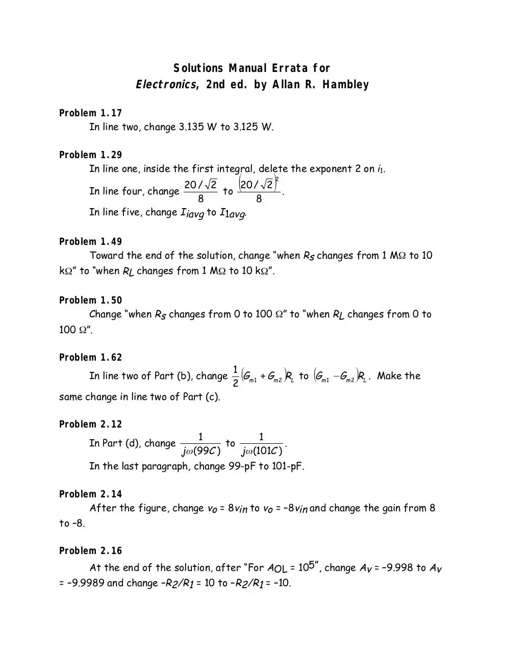
Solutions Manual Errata for
Electronics, 2nd ed. by Allan R. Hambley
Problem 1.17
In line two, change 3.135 W to 3.125 W.
Problem 1.29
In line one, inside the first integral, delete the exponent 2 on i1.
(
)
2
20 / 2
20 / 2
In line four, change
.
to
8
8
In line five, change Iiavg to I1avg.
Problem 1.49
Toward the end of the solution, change “when Rs changes from 1 MΩ to 10
kΩ” to “when RL changes from 1 MΩ to 10 kΩ”.
Problem 1.50
Change “when Rs changes from 0 to 100 Ω” to “when RL changes from 0 to
100 Ω”.
Problem 1.62
In line two of Part (b), change
same change in line two of Part (c).
Problem 2.12
In Part (d), change
1
(G + Gm 2 )RL to (Gm 1 − Gm 2 )RL . Make the
2 m1
1
1
to
.
jω (99C )
jω (101C )
In the last paragraph, change 99-pF to 101-pF.
Problem 2.14
After the figure, change vo = 8vin to vo = –8vin and change the gain from 8
to –8.
Problem 2.16
At the end of the solution, after “For AOL = 105”, change Av = –9.998 to Av
= –9.9989 and change –R2/R1 = 10 to –R2/R1 = –10.
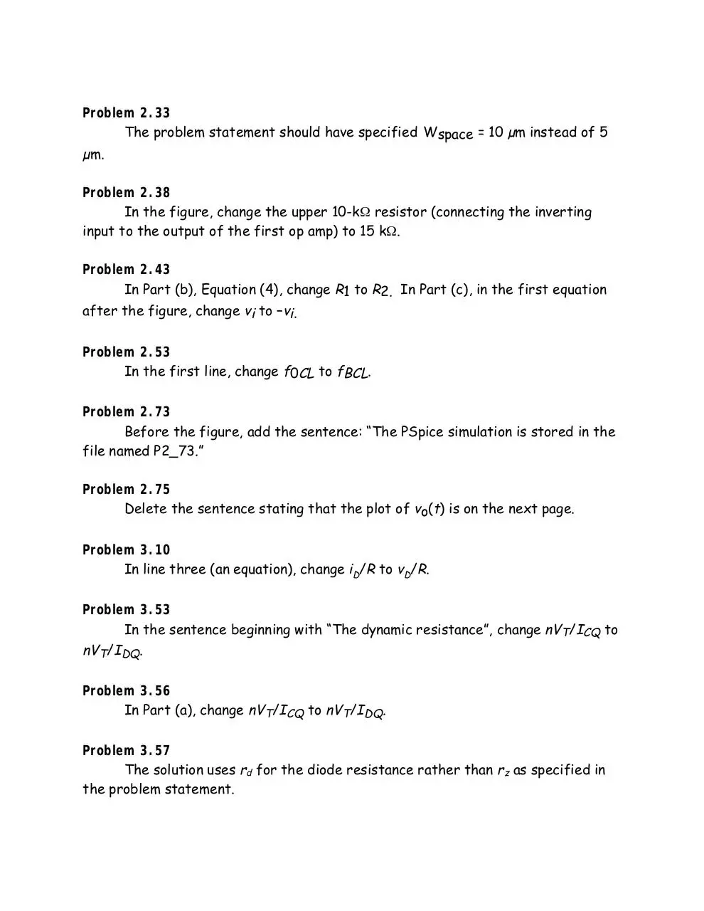
Problem 2.33
The problem statement should have specified Wspace = 10 µm instead of 5
µm.
Problem 2.38
In the figure, change the upper 10-kΩ resistor (connecting the inverting
input to the output of the first op amp) to 15 kΩ.
Problem 2.43
In Part (b), Equation (4), change R1 to R2. In Part (c), in the first equation
after the figure, change vi to –vi.
Problem 2.53
In the first line, change f0CL to fBCL.
Problem 2.73
Before the figure, add the sentence: “The PSpice simulation is stored in the
file named P2_73.”
Problem 2.75
Delete the sentence stating that the plot of vo(t) is on the next page.
Problem 3.10
In line three (an equation), change iD/R to vD/R.
Problem 3.53
In the sentence beginning with “The dynamic resistance”, change nVT/ICQ to
nVT/IDQ.
Problem 3.56
In Part (a), change nVT/ICQ to nVT/IDQ.
Problem 3.57
The solution uses rd for the diode resistance rather than rz as specified in
the problem statement.
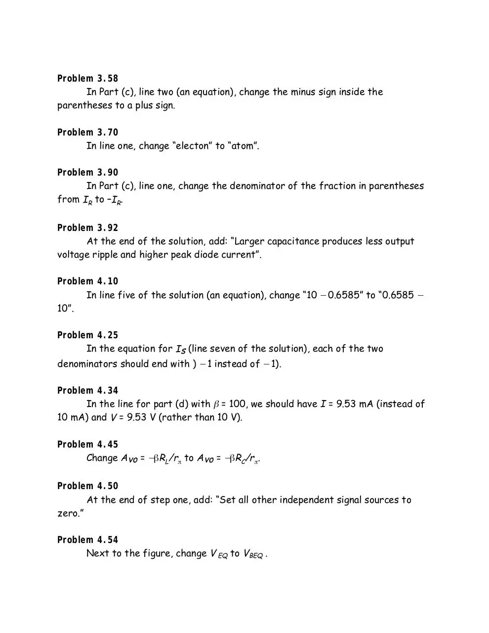
Problem 3.58
In Part (c), line two (an equation), change the minus sign inside the
parentheses to a plus sign.
Problem 3.70
In line one, change “electon” to “atom”.
Problem 3.90
In Part (c), line one, change the denominator of the fraction in parentheses
from IR to –IR.
Problem 3.92
At the end of the solution, add: “Larger capacitance produces less output
voltage ripple and higher peak diode current”.
Problem 4.10
In line five of the solution (an equation), change “10 − 0.6585” to “0.6585 −
10”.
Problem 4.25
In the equation for Is (line seven of the solution), each of the two
denominators should end with ) − 1 instead of − 1).
Problem 4.34
In the line for part (d) with β = 100, we should have I = 9.53 mA (instead of
10 mA) and V = 9.53 V (rather than 10 V).
Problem 4.45
Change Avo = −βRL/rπ to Avo = −βRC/rπ.
Problem 4.50
At the end of step one, add: “Set all other independent signal sources to
zero.”
Problem 4.54
Next to the figure, change V EQ to VBEQ .
Problem 4.60
In the first line after the figure, second equation, change IBEQ to IBQ.
Problem 4.65
In the first line after the figure, insert an equals sign after IB.
Problem 5.3
Calculation of the drain currents was omitted. The drain currents are:
2
2
(a) iD = K(vGS – Vto) = (W/L)(KP/2)(vGS – Vto) = 2.25 mA
2
(b) iD = K[2(vGS – Vto)vDS – (vDS) ]
2
= (W/L)(KP/2)[2(vGS – Vto)vDS – (vDS) ]
= 2 mA
(c) iD = 0
Problem 5.7
2
In the last sentence, change K = 25 to K = 25 µA/V .
Problems 5.23
The last line of part (a) should read: VDSQ = 20 – 2IDQ = 12 V.
Problem 5.25
Change the second equation from RSIDSQ = 6 V to RSIDQ ≅ 6 V.
Problem 5.46
Change “greater than zero” to “greater than unity”.
Problem 5.65
2
In the third-to-last sentence, change K(vGS5 – Vto) to K(vGS5 – Vto) .
Problem 5.74
In the sentence after the opening equation, change “saturation” to “triode
region”. In part (c) before the table, insert “Using the value of C given in part (d)
of the problem, we have:”
Problem 6.16
At the beginning of the solution, insert “The following solution is for an
inverter operating at 400 MHz.” At the end of the solution, add “For an inverter
–10
operating at 400 Hz, Pdynamic = 3.6 х 10
W.”
Problem 6.23
In the third line, change “IOL = –1 mA” to “IOL = 1 mA”.
Problems 6.24
In the first line, change “Pdynamic = If “ to “Pdynamic = Kf”.
Problem 6.25
In the equation for Energy, change (42 – 12) to (52 – 02) and change 150 pJ to
250 pJ. In the equation for Pdynamic, change 150 to 250 and change 3.75 mW to
6.25 mW.
Problem 6.32
In the circuit diagram, the device should be an enhancement MOSFET
rather than a depletion MOSFET.
Problem 6.36
Change the middle of the fourth line to read “VIH = 2.04 V, VIL = 1.08 V”.
Problem 6.51
At the end of the first paragraph, just before the figure, insert the
following: [Note: The solution assumes (W/L)p = 1. On the other hand for (W/L)p =
2, we would need (W/L)n = 16.]
Problem 7.1
Delete the comma after the phrase “high precision”.
Problem 7.11
In the first sentence, change “below” to “on the next page”.
Problem 7.18
Toward the end of the main paragraph, in the equation for R2,
insert a left-hand parenthesis the before 26mV.
Problem 7.20
Actually the current decreases when β decreases. Thus, the percentage
increase should be stated as -0.99%.
Problem 7.22
At the beginning of part (a), add the following: (Note: The problem should
have asked for proof that IO, rather than IC2, is independent of VBE.)
Problem 7.25
In the first line, change VCC in the fraction numerator to 10.
Problem 7.28
In the first sentence after the diagram, change P7_27 to P7_28.
Problem 7.37
In the third line, change (15 + VGS1 – VGS3) to (15 – VGS1 – VGS3).
Problem 7.38
At the beginning of the solution, add the following: “The problem statement
should refer to Figure P7.38, not P7.36.”
Problems 7.60 and 7.61
In the next-to-last sentence of each solution, change Acm to Avcm.
Problem 7.65
In the first paragraph, change the value found for Av1 from 64.6 to 36.23.
At the end of the solution, change the value found for the overall gain Av from
20.4 × 10³ to 11.5 × 10³.
Problem 7.66
At the end of the solution, add the following sentence: “The pnp stage drops
the dc level down so it comes out zero after the last (Q6) stage.”
Problem 7.67
Throughout the solution, change all occurrences of 2000πt to 200πt.
Problem 7.71
After the diagram, add the following: (Note: For the transistors to operate
in the active region, the emitters of the current sinks must be connected to -VEE
rather than to ground.)
In the third line of the main paragaph, change “Q3 is a simple mirror”
to “Q8 is a simple mirror”.
Problem 7.74
In the the top line of page 327, change (10 µA)/β to (100 µA)/β.
Problem 7.75
At the very end, change the value found for A1/A2 from 0.953 to 0.926.
Problem 8.8
In part (a) of the solution, the components of the phase plot are incorrectly
added. The correct phase plot should show a phase of +90° for low f , 0° for high
f, and should decrease in a straight line between 3.18 MHz and 318 MHz.
Problem 8.14
In the first line of part (b), change “drain” to “source”. Notice that the
expression abbreviated as B simplifies to Cgs(Rsig + RL′ ) + CgdRsig(gm RL′ + 1), and
the expression abbreviated as A simplifies to CgsCgdRsig RL′ .
Problem 8.18
In part (e), change “rd = ∞ (because λ = 0)” to “rd ≅ 1/λIDQ = 40 kΩ”.
Change the sentence about the break frequency to read simply: “The break
frequency is 251 kHz.”
Problem 8.24
Change the table to appear thus:
RL
RL′
Av
Rin,Miller
Rx
1 kΩ
995 Ω
–4.99
10 kΩ
9.52 kΩ
–9.05
33.4 kΩ
25.0 kΩ
19.9 kΩ
16.6 kΩ
Problem 8.25
Change the second line after the first figure to read:
Rin = Ri||Rin,Miller ≅ 0.1 Ω.
Problem 8.30
Change “Equations 8.41 and 8.42” to “Equations 8.42 and 8.43”.
Problem 8.33
In the second line change “Problem 8.33” to “Problem 8.32”. In the equation
for ic, change 50sin(2000πt) to 500sin(2000πt). Change the value found for
Ic,rms to 354 µA.
Problem 8.36
Note that in the equation for hoe, the current term
1
is small, and has
rπ + rµ
been ignored.
Problem 8.40
In the first line of part (a), in the equation for IBQ, change “100” to
“(1mA)/100”.
Problem 8.42
In the table, change the units of the right-column value of RE from mΩ to
MΩ.
Problem 8.43
In the middle of part (a), “Solving Equation (2) for vo” should read
“Solving Equation (2) for vπ”. In part (b), REF should be RE1.
Problem 8.56
′ = Rsig||RD to Rsig
′ = Rsig||RG.
In the second circuit diagram, change Rsig
Problem 8.66
The derivation of C1 should read as follows:
Thus, the input resistance of the amplifier is
Rin = RB||[rπ1 + (β + 1)(RE1||RE2||re2)] = 1046 Ω
The resistance in series with C1 is Rin + Rs = 1096 Ω.
C1 = 1/(2πf11096) = 1/(2π10 × 1096) = 14.5 µF
Also, in the equation for C2, change “1/(2πf21168)” to “1/(2πf21020)”.
Problem 9.7
In part (a) of the solution, the final equation should read
A1A2f
A1A2
X
Af = o =
=
X s 1 + β2A1A2f 1 + β1A2 + β2A1A2
Also, in line four of part (b) change A2 to A3 and change “a a gain” to “a gain”.
Problem 9.10
Change > to >>.
Problem 9.14
Part (a) uses | VBE | = 0.7 V in saturation, not 0.6 V as specified in the
problem.
Problem 9.35
In the first line, delete the second occurrence of ii.
Problem 9.44
In the last line, change “parallel” to “voltage”.
Problem 9.45
The last sentence, should read: “Since we want Aß to be very large in
magnitude, we choose small resistances for a current feedback network.”
Problem 9.47
At the very end of the solution, change the units of the value found for Rof
from Ω to kΩ.
Problem 9.49
The problem should have called for Rmf = –5000 Ω. In the solution, change
the units of the value found for Rif from MΩ to Ω.
Problem 9.51
In the third line of part (a), delete the second occurrence of vi.
Problem 9.52
In part (a) change the equation that begins line four to
RL
= –417 MΩ
vo/ii = −Av Ri ×
Ro + RL
In the last line of part (a), add a negative sign in front of the value found for β. In
the fourth line of part (b), change β = 1/Rf to β = –1/Rf.
Problem 9.53
In the third line of part (a), add a negative sign in front of AvoRi. At the
end of part (a), change the value found for β to –2.16 × 10⁻⁵. In part (b), in the
first line after the diagram, add a negative sign after the = and before the
fraction.
Problem 9.59
In part (d), change both instances of “1000t” to “100t”.
Problem 9.64
In the last line, change 3500 Hz to 350 Hz.
Problem 9.66
In the next-to-last line, change “imaginary” to “complex”.
Problem 9.72
In the next-to-last line, change 180° to –180°.
Problem 9.86
In part (c), the last two sentences should read: “Finally setting Aß = 1 yields
A = -29 and ω = 6 /(RC ) . Thus an inverting amplifier is needed.”
In part (d), change the sign on the last term from – to + in the denominator
of the second equation.
Problem 10.11
Delete the closing parenthesis after 0.0025 in the middle of the first
equation. Change the value found for θJA to 150 °C/W.
Problem 10.23
The trigonometric identity should read 2sin2(x) = 1 – cos(2x). In the integral
equation that follows, change 10sin(4000πt) to 10cos(4000πt).
Problem 10.27
In the fifth line, change the integrand to [1 – cos(2ωt)].
Problem 10.35
In part (a), change (VCC / 2 )RL to (VCC / 2 )2 /RL .
Problem 10.37
In part (d), the final equation should read
PQ1max = (VCC/2) × VCC/(2RL) = VCC2 /(4RL) = 7.03 W.
Problem 10.45
In Equation 10.49 in the text,
R2
R + R2
should be replaced by 1
.
R1 + R2
R2
Problem 10.50
In the second line of the solution, change “op amp” to “transistor”.
Problem 10.63
In the second line, change “on the next page” to “below”.
Problem 11.16
In the equation for C, insert a closing square bracket after the L.
Problem 11.21
In the third line of the solution, change ωR = 3ω0 to fR = 3f0 .
Problem 11.37
In the first line after the last set of diagrams, change
2
Q2 = RL / Rs to Q2 = RL / Rs .
Also note that in the first diagram of the solution, Rs represents the
internal source resistance, while in the rest of the solution, Rs represents the
series equivalent of RL.
Problem 11.38
Note that Rs represents the series equivalent of RL. In the second line, note
that QC = 10 and change the value found for Rs to 5 Ω. In the third line, change
4.47 to 3.16, change 1423.5 to 1006.6, and change 409.77 to 465.2. Then the
simulation results closely match predictions.
Problem 11.39
Note that Rs represents the series equivalent of RL. In the second line,
change the value found for Rs to 50 mΩ. (Note that QC = 100.)
Problem 11.45
In part (c), change 256.51 pF to 316.43 pF and change 20.21 nF to 1269 pF.
Problem 11.50
Note that in the solution rd has been taken to be very large.
Problem 11.54
At the end of the solution sentence, change the period to a comma and add
“or approximately 20 MHz. The third overtone frequency is about 30 MHz.”
Problem 11.57
Note that “antiresonant frequency” means the same thing as “parallelresonant frequency.”
Problem 12.11
Note that in the solution, “node 2” refers to the noninverting input.
Problem 12.12
After the first paragraph, change vo = VB + 4.7 to vo = VB – 4.7. After the
second paragraph, change vo = VB – 4.7 to vo = VB + 4.7 and change vin > VB to vin <
VB. In the plot at the end of the solution, change
–1.3 on the y-axis to –1.7.
Problem 12.17
Note that in the problem statement, the v2 referenced in the ninth line
should be v1 .
Problem 12.40
At the end of the solution, change ioR/2 to –ioR/2 and change 9.96 V to –
9.96 V.
Download Electronics - Hambley - 2 edicion
Electronics - Hambley - 2 edicion.pdf (PDF, 30.43 MB)
Download PDF
Share this file on social networks
Link to this page
Permanent link
Use the permanent link to the download page to share your document on Facebook, Twitter, LinkedIn, or directly with a contact by e-Mail, Messenger, Whatsapp, Line..
Short link
Use the short link to share your document on Twitter or by text message (SMS)
HTML Code
Copy the following HTML code to share your document on a Website or Blog
QR Code to this page

This file has been shared publicly by a user of PDF Archive.
Document ID: 0000036708.