wiring blacktop (PDF)
File information
This PDF 1.3 document has been generated by Canon SC1011 / MP Navigator EX, and has been sent on pdf-archive.com on 14/03/2013 at 01:45, from IP address 173.178.x.x.
The current document download page has been viewed 1383 times.
File size: 5.67 MB (9 pages).
Privacy: public file


File preview
Black Firc,"rall pIug '/$iring:
..\-tr :,t-O 1i1ii.- .'. tt.: t,. l;'t-T:t:"i?t'{ X}ti'}it:t it111;.atr:'s'' <LX tl>";:4''\i l\;itt1t:""'
.-\,. f.lr. ,:=:,n.rr .,t,']:.\, ijt''.4j
*, , rrl !...,"-;ll;- i.:;*- i;. .t.r,t.- 1 .\": .,' .''i .'.tza
ii}i -'!:'?''Pi?:2..'1i ''e''ri|'t t.1: tr'}"::
**.i. i'[1 ,:l:it^rr.'r,* ,".1i,' rvtrtrt,llir{"
\ , 1. Y1,1,'tii i'. {iq*r.:;'n': l 'r,r'rr
., ..^rr,lr,
4l''1
'4.'il+r'*?.
)',,- -'tr1.r."
'' 'a-
\
\
-
}
stnrtrei
\
Flu{,
c6nnedt h€re
r.*rrr;
,'1
tr
,. ?,i-rt-\, I'
;,r t, Liij,i.t,*,;1.2..]
!tr;- |:h.i.tt
li l - *+tt1tl.,t
i.
*,,.r,
i..r.'it?01;r'.7t1':':1':1rii2:ai;1111,i''t1t4"io"i'lttl:!t.i!lt")
.L:.t::r ,::i ,,',,lt,,i1,r.t
.
.. ,i.r. ;i,1. :,.,. ;,. .,
1, ,,1 '. i.t...rt,,.'..':
::'-. . 1 i t, , 1 .-
SPE tsir€ el 16V
ECU lrody harn*+
into *3'of
1.Ill:,{i
tri
\*i,'
To
I
GENr$IflT
<rearn {u*e
fonne{tD r
b*x
lrameslj EEfiiBLK
-1:
Retnov+rNot
uied
Circrlit Spen Relay: (r:trn,-t
I
j,
GR N,'RED
oI€OR t0 thi, pin
,.;
Fage ?
a'l
crf cv.earir
fure
bog
Black Fir*,"'rsll plug
wiring:
t,. t;!-E:tj'i?t'{ x'iti'};t::, i11r'i:'.t':'2'tLltli':;:i3\il\;ntt1t:"";
-*\rtr i,1-ii.){:i--.'. tt':
.-\,. f.li,. t::i,e,1r ,,tq,)t\, tlt'...j
r. ..j";lli- i.::.t-i;. .i rrNr- 1 .l"r.r .'.i .'.tid
*,,,,1
-t:'?\'PN':-2..'\i 'e'!t'1 | t.1:t{t'i:
f O;.t[1 ','.[]lr-rJ.'r>c,".ti,.rzt.'lt.:i''r"*.'i]i
\ ; . iz1,lr,tjig. lri*1:,..",: r il,r.q,
#4
&*I
@
sg
,t
t
+1&
W
f]
&
e,
#7@
W\r
Cfro
w*
Wr
ouru
iti:t..::fttyrX,q
,':rt-
f
:{
'1'
trl r.*rrr; tr
\; i,, ,,1,. t,i.r:
\,, t t, Liij,i), a;1. ]
!tr;- ,t:t11.i'lx
i1,x.t 1..
t
a1i-
conne{t h€re
1;
::'-
'..
r I 1
,.li
",:'N
,.,
1,,it,T.
.
t
r. ,ii
i.'t.'\.tt
t.
,
t i.".
1'
':.
.-
e*rr or 16v E(u
I [r+dy
h.rr fiett
|
I co lr ne(t, here
.{
To GRfdTWHT
{u** b*x
fonne{tt r
<rearn
,,|
5.
i
:;i i
*izrr:tl..t
|i..' ,,,'|
;'
i
L:.r::.'.,:
.1. -1r,,t,..
. t,*.1.. ii, i.
SPE teir€ el 16V
ECU trody harn*+
Flu{,
.' ,ll
\
\
itnrtei
irrto *3'of
I
I
I
I
t
(ofine(t to
,,,
Rerrov+rNot
ured
I
ICircuit Opetr Relay:(orrrr,rt GRN'RED
thir
i..ol€OR to
pin
__l
I
}:
Fage ?
i'i
1
EL!{ power:jtl'iligtt,fon
oj.}ftt
hanregci ftED,tBtKaf <.igafrr fu:e b+1g-
(ollne{toY
. -, :j
'4.'il+t*t.
$.*t*1''t'.'
}
s3-
41''1
For some reason
this information is not all in one piace on this site, if at all, so hopefully this can help you guy's
in your searching and
researching.
''
This is using a complete ae111 wiring harness and ECU, and a complete gt-s - ae86 engine harness. iused ae86
alternator, starter, and a/c.
you should have a good understanding of how to do wiring, soddering and the basic understanding of how
cerciut works.
a
Start by marking evertT plug as you pull the harness off the motor, then remgve all the wire lume from harness,
rap electrical tape once or twice around the wires every 6 inctres or so, also where ever wires spiit off or come in
this is to keep the wires neet.
Do the same for the ae111 wiring harness, where the harness passes through the fire wall there is a cast ruber
lume compression thing going on, be real easy and cutthe rubberas.you pull each wire out individually, try not
to cut the wires, after marking all the wires.you can start removing what is not needed, just go slow and trace
where stuff is going and where it came from. .
after you have both of the harnesses out and labled, and the ae111 harness reduced to what you need, you
basicly cut the wires out of the ae86 -gts harness and sodder thenr in the ae111 harness where needed.
Heres what worked
{or me
I,
There are
.
sif&nqfuiltl6t
(1.) ae111 ecg pl&s
.i
i
you are ciealing with when doing a b/t to ae86, gt3 swap.
,'26 pin conector
(Z.l ae111 ecu plug 2 ,1ri pin conector
(3,)-Sel11 ecu plug
**
3,22
pin conector
(a.) ae86 elu plug t , 14 pin conector - comes off in car harness
(5.) ae86 fire wall harness , 11 pin conector
il.
(6.) ae86 engine harness "not ecu" ,
F pi" conector - goes to fuse and relay box near ecu.
rc
ta simplify thinGj'tl refer to these plugs as stated above.
\
f\ r;
the ae11l swap to the ae86 most of the wire forthe (1.) ae111ecu
rf \in
! exept for the els1,.els2, els3 and cf pins witch are not needed
plug 1 , 26 pin conector are unchanged
in this applicltion.
iry
# o"+ft r;,;,
on^t!.e(3.)ae111 ecuplug3,22pinconectorthereare6wiresthatnbedstobehookeduptoit'sptaceonihl
wlrerng.
lfYtr'q.l
starting at the start. this is first (3.) ae111 ecu pin then where it hooks to on ae86
i'
\r,u,
blk-w - to (5.) ae86 fire wall harness blk-w wire also - spit to startersignal wire blk-w
.r+
.\
-\:;,'"."
cold air
;t \
'ln
.#
t
..i
:.\.
,et"i{h
not needed, you do however cut the w.ire for the a/c magnetic clutch for the aeg6 ecu. my car does blow
sp1, purple/w - to (4.)ae86 ecu plug t, blue/w - for speed sensor
\
\
G. V
w,
*- Vrc,
t/y
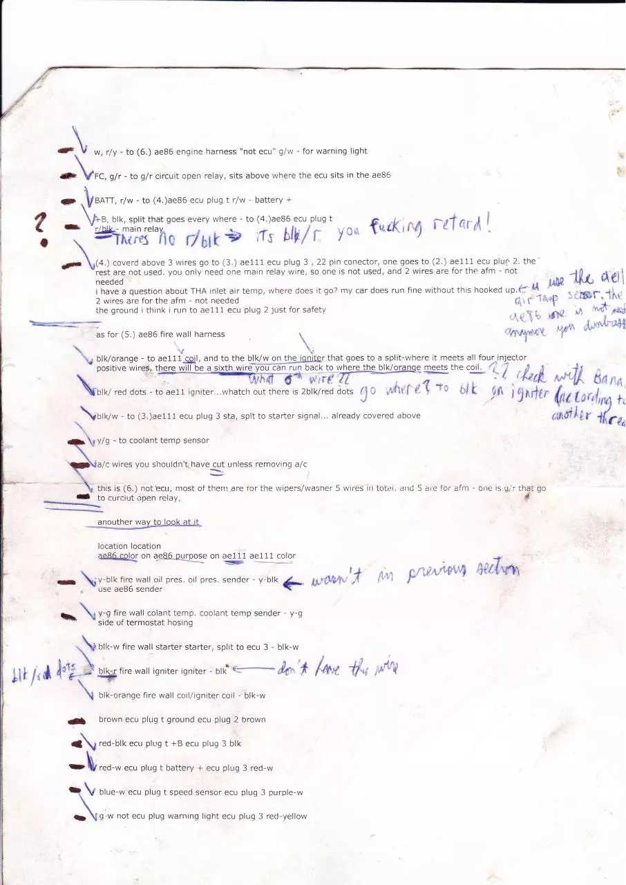
-to (6.) ae36 engine harness "not ecu" g/w
\
t
forwarning light
q/r - loglr circuit open relay, sits above where the ecu sits in the ae86
.VsaTr, r/w - to (4.)ae86
',
-
ecu plug
t r/w - battery
+
brk, sprit that soes everv where - to (4 )ae'6
"'irir
- \ Ygr=ffi[*"I't rlUtk# ;f,r bll,
.
r
y
*,,, furK,
rg
i-E1 qi
di
\
coverd above 3 wires go to (3,) ae111 ecu plug 3 , 22 pin conector, one goes to (2.) ae111 ecu pluq 2. thegf \f+,1
-::r;,rXT not used. you onl.v need one main relay wire, so one is not used, and 2 wires are for the ut, - no,.
-1flC tlel
f*n
.,
temp' where does it so? mv car does run fine without this hooked
:,. ffil-.1irt
"r{lir.p
;T[:r'J-:?1i?,"':?Ht-',i] l:::il
thegroundithinkiruntoaell1ecuplug2justforsafety
r,.1 \\rts3
,r,,Xt,
tt ' rdN
k'=:T
_"
_. -f
rral,\ ,"{*'*&*"4t
as for (5.) ae86 fire wall harness
"flV1+:{(
\
1
\ ;':, ""
t\
|
iffi
blk/orange - to ae111gil, and to
\
th" blygq,l.ugjgllgf that goes to a split-u;here it meets
all..four injector
,trffiffiffi ":;*'i!,,, f!;, fi(;,,ii;;
/;iohfiL
.\0,07*-to(3.)aelllecuplug3sta,splttostaftersignal...alreadycoveredabove
[
v/o - to coolant temp sensor
+.\
I\
I
wires you shouldn't, have cut unless removrng a/c
1\=
-\a/c
\
.
+-'l
F*
tI
this is (6.) notecu, rnost of tlrern are ror rhe wipers/wasner 5 wrrcs rr toi1,r. arrtj 5 ar'e f or
to curcir.rt open relay,
airi - orrri rs url ihaL
$
l.=-..--.-----
I@
tI
I
tocation location
ae.Aelglg' on ae86 ouroo_se on de111 ae111
t
-
fI
tI
I
t
[,u
color
fire watl 11il pres. oit ores. sender- v btk
\r-O,O
- use ae86 scnder
+.
-
f.-- \
1\
7'*
l'"t{
|
I
I
I
t
I
I
t
I
f
a\
t\
y-g fire wall colant temp. coolant temp sender - y-g
- side of termostat hosing
bll<-w fire wall starter starter, split to ecu 3
- blk-w
ffi:,:,:;.#"."::;
h"'* /a'r -{f";'*t{i
t
I
I
+ {ri',
a,
1S:*Vt,'' f
t
brown ecu plug t ground ecu plug 2 brown
red-blk ecu plus
*
t +B ecu plus 3 blk
ecu ptug r battery + ecu ptug 3 red.w
-IUruo
o,ru-* ecu plug r speed sensor ecu ptug 3 purple-w
-\
\olw not ecu plus warnrng liqht ecu ptus 3 red-yettow
I
r,f"'ti,,''it/v'4
' I
'ti/'{'{+'
go
l- irr,
;\
n-. circuit open relay CoR ecu plug 3 g-r
i mest up anywhere, my car fired right up with this set up. and has run for 20 thousand
miles as of 2/O8.. and sold the car with no problem had
Please let me know if
if i have any more information i'll revise this post, good luck.
i added a diagram and 2 pics of sorne of the notes i took,.. i spent as much time reaserching and figureing this
out as i did on the rest of the swap. i haave 5 more pages of notes, but there conte.nts are in this post. ecu pin
outs for the ae86 are in the tech referance section of this club
P]\'i
#86 UILtf
Pl,ng
U pluo
1*P
Cr.ll5
18p
T $rlu4_/
14p
Pir"l*r-rt by:
V Connector
Pin No.
Symbol
Color
2
VF
J
ST
R-L
B-W
-fcrminal
Check connector
Starter switch
FI
t
(s1'A)
4
801
6
VSV(siTH)
l'
i
I
10
5
F
;--
No.
Y
BR
R-W
7
E1
BR
8
IGT
No.20
802
B
G
t'
9
Y
10
BR
No f 4 iniector
Engine ground (Power)
Vacuum su,itchirg val.;e iS/TH)
-)
Ensine ground
Igniter
No I 2 iniector
Engine ground (Power)
Wnndy
/
U Connector
Pin
\o.
1
Terminal
Svmbol
Color
NE
R
Engine revolution sensor
G+
B
W
Ens ne revolution sensor
Eng ne revolut on sensor
')
-l
G-
4
IGF
IDL
T
WAN
6
7
8
B-Y
L
I,G-B
G-W
Isniter
Throttle sensor
Check connector
Wamine lisht
9
10
1i
t2
13
t4
15
i
THW
VTA
VCC
OX
821
A/C
B-W
VUP
B
G
R
I,-R
B
RR
Water temp. sensor
Throttle sensor
Throttle sensor
Oxygen sensot
Sensor Earth
A/C Magnet clutch
16
17
t
l8
I
I
(vis(
Vacuum switching valve [Idle up]
)
I
I
l
T Connector
:
Pin No.
Svmbol
Color
Terminal
1
+R1
B-R
R-W
Y
Main rela
2
a
J
4
5
BaTT
THA
VS
VC
Y-L
L-R
Inlet air temp. sensor
A r flow meler
A r flow meter
+B
B-R
Main relay
SPD
L-W
Speedometer
E2
B-R
Sensor eafth
6
l
8
9
10
11
12
r3
t4
,-
f,t" i |
i
:
?,r4;lr** E*U Termtmls
4
@
Tar#rwt
?#fat{lt; }Wvw
ffi,
HeffiE
W€€ &*#iND
*{##rffi
w?n
#1
ffi
W*,W*fr
ffiEfiTffi
&*
fHffifi{rtffi
HS*
I.ffiV*lffi
ffi'
E1
vr
lwT
TE1
*x
ffi
[ffi
&$1
ffi,ffiffiffiffire#ffif",W
H#$rEu#ffiffi w*w
x,r,qggg
e;*
ACT
fiPl
Affi &M*LIY1,SIM
sPggB sEltffifi
w
${AftffiT-*G TJGHT
F*
$*tr4#L{{T
#d,rtPLtFlBffi
*F4E*H ffi$#hffiST#pl
w?
nffi$gH&ff#
&E#t***dfi" r*f;
&
HSIK
Kr'*fitr{ s€N$#fr
Br,f,rffiEH&XffTGH
El*ffi t T&lLI"Gt'ff ftEl-AY
TFfitr
W&18ffi TEMF.&HHS*ft
K*fi?trH
q.'t
t
Lr*ffi!&ryr.I&1ffiffi
f:Ig
W
&*t
ffi*&FTffi.ffiTffiVELYE
EI
EC
&*.s.&Fl
€t
Tm*rr# Hffir6
E**!t'{E #**/"l,W*
cHE*f( **r*f"J&trron
rff
ruffi Brffiffifi fi&eY
gr.
W
I
1
d
I\+{
ffiT&HE
vT&
?lffiTTLE Fffil'ffiH &:FTffifi
Ft#
ri*#lfi.$*t
*fi/,affi*{&tTrugii:Hffi
ffi L*##
ffi#*#€#ftffi#feffi
yfi
w ffiffiFfpffiffiffis
tilt{*
ffif*r&ft
W
w+*r$#
N*TB&F.ffilSffi
EE
gr&
g*.r#ffi
effiffi, ??#$rflL*
$*tr?ffi{ffi*ffi
&€e*ffi ffi,&*ris*r
Vfi&,tq#
ST&ffi?Bft frELs'Y
r*N-ffi
p&.al
ftgl*4Y
AWlw#&*J?*tt#n#
#f;Ft}F*.*
E&TT
*&YTHBY
?11
*^T,-rwr{
ffi
gr.SY
that need to be sogrced from lEV harne*s:
-Elack I Tpin Firevrall plug
{reenr l4pin Fule hox ranneetor fbr wiper opp+rationr/CEt
Pnrta
Fage #1
$Iiper lBoto r Frep Secr ion :
{acate the rresm 'l4p in conncto r of i6il ht.rter l. Th i: cornecto r p lugr irrto the pe: ierrEer r ide fuse hox and eohtd in r
rhe uriring lo r t6e wip*r
oF€ritioft, &llL light, {ireuit Opetr Relay, *ncl Battery power. Remuv* ihe tape frernr th* 15V harnerr *ncl reparate lh* wires
althiE plug from ihe
IEstoftke16Yharne**.ereatingaprepharne*,Afterdoing,o(urthe6BlrllWHT,GRlCIig.arrdBLK,,REDuire,oItlr*"reirn plugallowinEabout
6sincherof wirertill attarhetltotheirearn ptug.Thewipeip.*p hurn*iliilillt iiTl-ijif rhir,-
'ia.
|t,
'l
tt,,.t*
."
-l illttlt
-r-a
-
theprcp re{tioti {ompleted, remove ihe dR}lfHED erieof the prep harn
will h€<ometheMlt lighr t*ire.fonl<t ihe6.S-Ujli&H-Trvirep.tlin_][k[drg
tlrri alro r€nne(ir ro
exit thewirinq hsrnerr wirh rhe Ee [t plugt it the fure box i,
t" rt,.e ft[
Whh
lhir
is theold COR
wieand ir nor nmled,TheGRNAUHTuire
;'#E!gj!.Ihe Etlt EEf.:rqirlr urill go to rhe BLK rvire n+uer
ith wirer <orrnxted the rrearr ftrre box plug rh**ld- . i".,
.
^ext
l\
ra7
Download wiring blacktop
wiring blacktop.pdf (PDF, 5.67 MB)
Download PDF
Share this file on social networks
Link to this page
Permanent link
Use the permanent link to the download page to share your document on Facebook, Twitter, LinkedIn, or directly with a contact by e-Mail, Messenger, Whatsapp, Line..
Short link
Use the short link to share your document on Twitter or by text message (SMS)
HTML Code
Copy the following HTML code to share your document on a Website or Blog
QR Code to this page

This file has been shared publicly by a user of PDF Archive.
Document ID: 0000098073.