Spotty V1 Manual (PDF)
File information
This PDF 1.4 document has been generated by Writer / OpenOffice.org 3.4.1, and has been sent on pdf-archive.com on 07/05/2013 at 21:21, from IP address 89.164.x.x.
The current document download page has been viewed 3687 times.
File size: 7.68 MB (8 pages).
Privacy: public file


File preview
Spotty v1
User manual
Spotty v.1
Wire welding device
by
HELEX
&
VonMacher
User Manual
Made in Croatia
1 of 8
User manual Version 1a, Date 05.05. 2013.
Spotty v1
User manual
Device description
Picture 1
Picture 1: Basic layout
Technical specifications
Power supply:
9V 6LR61 Alkaline or NiCd/NiMh rechargeable block any DC
power supply up to 24 V
Output voltage:
up to 37 V DC, adjustable
Charging time:
up to 3 sec (depending on output voltage setting)
Battery life time:
up to 10 hours (device ON) over 500 charging (spot welding)
Weight:
152 gr (w/o battery)
Dimensions (L×W×H):
130×68×25 (53) mm
Made in Croatia
2 of 8
User manual Version 1a, Date 05.05. 2013.
Spotty v1
User manual
Special features & protections
Reverse polarity protection - device is operational no matter of power supply polarity
turnover.
Output short circuit protection – if output terminals are shorted while charging button is
pressed, automatic protection feature will cut output current to minimum.
WARNING! Shorting the output terminals will never harm the device, but battery life time
significantly decrease!
Charging voltage regulation – charging voltage can be controlled in two ways:
● Via regulator knob (2) steplessly. This will determine the maximum charging voltage.
● Via charging button (3). Charging time of cca 3 seconds allows you to monitor charging
voltage and terminate it at any desired voltage lower than maximal
determined at regulator knob (2).
Precision welding support – provides high precision wires aligning and welding even in low
visibility conditions. Reduces number of faulty welding attempts to minimum.
Safety precautions – since Spotty v1 uses a low voltage welding technology (same as all
spot welders in car body shops for instance), there is absolutely no possible danger of
electric shock or any injuries what so ever.
Working principles
Spot welding basics
To create a welding spot it is necessary to provide a high energy boost in a very short
period of time with losses as small as possible. Those losses are mainly electrical
resistance created by bad contacts and if not eliminated they will significantly decrease
welding quality.
Further more, while welding, it is necessary to have almost the same condition for every
welded spot, to be sure that result will always be satisfactory.
Electrical losses by means of resistance are mainly created on connecting points, but also
at the welding spot. Therefore both wires (NR and R) must be well clamped (R wire as
shortest as possible to reduce its internal impedance), and welding points on wires must
be clean of any residual dirt (greasiness, patina, previous welding attempts coating).
Made in Croatia
3 of 8
User manual Version 1a, Date 05.05. 2013.
Spotty v1
User manual
Welding with Spotty v.1
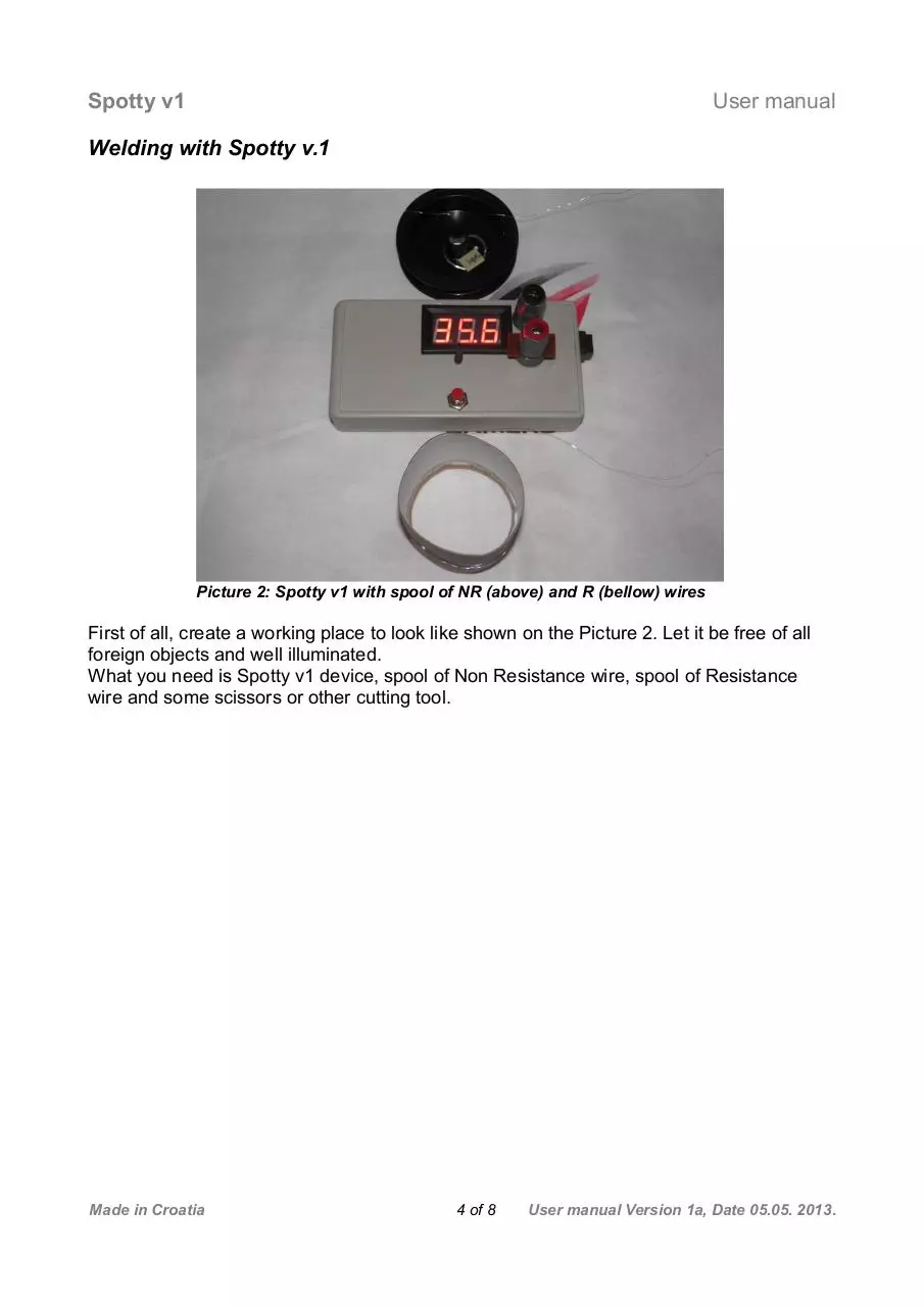
Picture 2: Spotty v1 with spool of NR (above) and R (bellow) wires
First of all, create a working place to look like shown on the Picture 2. Let it be free of all
foreign objects and well illuminated.
What you need is Spotty v1 device, spool of Non Resistance wire, spool of Resistance
wire and some scissors or other cutting tool.
Made in Croatia
4 of 8
User manual Version 1a, Date 05.05. 2013.
Spotty v1
User manual
Let's create a good connections
Please note end terminal holes. It is
mandatory to protrude wires through those
holes and clamp it with upper nut.
Note: NR wire can be wrapped 1 round
around the black post screw and clamped that
way.
That will ensure the best possible electrical
connection and reduce losses to minimum..
Picture 3: End terminal mid holes
Resistance wire must be clamped on RED
post. To do that, please unscrew red plastic
nut, protrude wire through the mid hole
(Picture 3) and clamp it with red plastic nut
(fingers only!).
Let wire lies on support like shown on Picture
3. Straight ahead, or even 45o toward black
post could be better, depends on personal
customization.
Note: Up to 5 mm should be good enough. It
is mandatory to have R wire protrusion as
short as possible, so its internal impedance
will have less influence to welding result.
Picture 4: R wire clamping and aligning
Picture 5: NR wire clamping
Made in Croatia
There are two good ways of clamping the NR
wire.
1. Protrude it through the mid post hole and
clamp it.
2. Wrap it around the black post screw and
clamp it that way.
Both ways will provide best possible electrical
connection and allow you to easily prolong the
wire when needed. Just unscrew a bit and
pull.
Wire should protrude long enough to be easily
guided by fingers toward red post support.
Approx. length 10 cm.
Note: Please don't prolong NR wire to much
since its internal impedance can decrease
welding result!
5 of 8
User manual Version 1a, Date 05.05. 2013.
Spotty v1
User manual
Welding procedure
Now it's time to charge the device and weld.
1. Turn the device ON (switch 6)
2. Adjust voltage if necessary (regulating
knob 2)
3. Press charging button (3) and watch
voltage increasing. It will slow down and
finally stop at preset voltage.
4. Release the charging button (3)
5. Slide NR wire over the support surface,
align it carefully to R wire and make a
connection. Let wires overlap for at least 1
– 2 mm. Connection will create moderate
spark and some noise. It is normal, there is Picture 6: Aligning and welding procedure
nothing to worry about.
(please note the wires overlap)
Now you can unscrew the red post nut and
pull the R wire to the desired length
(resistance). At this point you can attach the
ohmmeter to output posts to measure future
setup resistance. Just remember to clamp red
post nut.
You should get something similar as shown
on the Picture 7.
Illustration 7: First welding spot is made.
Cut the NR wire at desired length. Unscrew
black post nut and pull NR wire out to get
length of previously mentioned aprox. 10 cm
and tighten it again.
Now fold R wire (with already welded one
side) to the left (opposite to black post) and
align it to support. Please refer to the Picture
8.
Now you have other side of R wire ready for
welding and inline with NR wire.
Picture 8: Folding R wire enables inline
welding
Made in Croatia
6 of 8
User manual Version 1a, Date 05.05. 2013.
Spotty v1
User manual
Using the same method explained before,
weld NR wire to the other side of the R wire.
Please refer to the Picture 9.
Picture 9: Welding the other side
After welding is finished, you will get
assembled wires like shown on Picture 10.
Use scissors or cutter pliers to cut R wire as
closest as possible to the welding spot and
NR wire to desired length.
Note: After some practice you will be able to
adjust Spotty to burn out the rest of R wire, so
it will fall off the red post automatically,
creating at the same time almost perfect
welding spot.
Picture 10: After welding the other side of
R wire
Note: It is possible to use another method for welding the other side of R wire. Instead of
folding it (refer to Picture 7), you can cut the R wire to desired length (resistance), unscrew
the red post nut, remove spooled R wire and protrude the other side of R wire in process.
Clamp it and align it in exactly the same way as you did in first attempt and proceed with
welding procedure as explained before (refer to Picture 4 – 6). The result will be the same,
but it will last a bit longer to prepare.
Made in Croatia
7 of 8
User manual Version 1a, Date 05.05. 2013.
Spotty v1
User manual
Care and maintenance
Spotty v1 demands almost no maintenance at all.
Nevertheless, some things you should keep in mind.
Battery has to be changed when adjusted voltage is not reachable.
Take out worn battery carefully. Don't ever pull battery connector for wires, you will
damage it.
If device is not to be used for a prolonged time, disconnect the battery.
Keep the device in a dry place. It is not intended for outdoor usage.
Never leave the device switched on if not in use. It will flat out the battery.
Picture 11: Battery compartment
Troubleshooting
Desired voltage is not adjustable
• output voltage can be adjusted to max. 37 V. If this or every lower value is not
reachable, please replace the battery.
Spot welding quality is poor
• Please check all electrical connections as described in this manual.
• Please check the wires on its ends (welding points) for any residual dirt.
• Please check the charging voltage. Maybe is necessary to rise a welding voltage.
For instance, changing the wire type will probably ask for welding parameters
change.
• Be sure that R wire don't protrudes to much from red post. You should perform
welding approx. 5 mm away from post on the support.
If your first attempt is not satisfactory, just charge and try again. Maybe it will be necessary
to cut few millimeters of wire ends to have a nice clean surface.
Please don't press the charging button while wires are still connected. It will not damage
the device, but will drain the battery with no welding effect at all.
Note: It is mandatory to make a few tests and to have some practice. After few welded
spots, number of faulty welding will be insignificant.
Made in Croatia
8 of 8
User manual Version 1a, Date 05.05. 2013.
Download Spotty V1 Manual
Spotty_V1_Manual.pdf (PDF, 7.68 MB)
Download PDF
Share this file on social networks
Link to this page
Permanent link
Use the permanent link to the download page to share your document on Facebook, Twitter, LinkedIn, or directly with a contact by e-Mail, Messenger, Whatsapp, Line..
Short link
Use the short link to share your document on Twitter or by text message (SMS)
HTML Code
Copy the following HTML code to share your document on a Website or Blog
QR Code to this page

This file has been shared publicly by a user of PDF Archive.
Document ID: 0000103647.