StaiCPhD (PDF)
File information
This PDF 1.3 document has been generated by / Acrobat Distiller 5.0.5 (Windows), and has been sent on pdf-archive.com on 19/08/2013 at 21:08, from IP address 92.234.x.x.
The current document download page has been viewed 1086 times.
File size: 3.18 MB (128 pages).
Privacy: public file


File preview
Study of stair-climbing assistive mechanisms
for the disabled
Murray John LAWN
Dissertation submitted to the faculty of Mechanical Systems Engineering
For the Degree of Doctor of Philosophy
Graduate School of Marine Science and Engineering
Nagasaki University, Nagasaki City, Japan
December 2002
i
Table of Contents
1
Introduction ..................................................................................................................... 1
1.1
Why stairs?................................................................................................................. 1
1.2
Stairs - are they safe?.................................................................................................. 3
1.3
Wheeled mobility ....................................................................................................... 4
1.4
Wheels and stairs........................................................................................................ 5
1.4.1
2
Motive force, curb height and wheel diameter.................................................. 6
1.5
Requirements for stair-climbing mobility .................................................................. 9
1.6
Common stair-climbing techniques and assistive devices ....................................... 11
1.6.1
Assistant based curb, slope and stair negotiation techniques........................ 11
1.6.2
Common stair-climbing and van entry assistive devices .............................. 13
1.7
Stairs - discussion..................................................................................................... 15
1.8
Thesis outline ........................................................................................................... 16
Recent advances in mobility assistive devices for stairs or curbs ............................... 18
2.1
Curb assistive mechanisms for wheelchairs............................................................. 18
2.2
Curb capable powered wheelchairs and mobility scooters ...................................... 19
2.3
Tracked based stair-climbers.................................................................................... 21
2.4
Lightweight wheelchair stair-climbing attachments ................................................ 23
2.5
Wheel cluster based stair-climbers........................................................................... 25
2.6
COG modification wheel cluster based stair-climber .............................................. 27
2.7
Dual wheel cluster based stair-climber .................................................................... 29
2.8
Miscellaneous stair-assist and van entry mechanisms ............................................. 30
2.9
Recent advances in mobility assistive devices for stairs or curbs, summary and
discussion ................................................................................................................. 31
3
Proposed high step and stair-climbing mechanism........................................................ 35
3.1
Introduction .............................................................................................................. 35
3.2
Proposed mechanism................................................................................................ 35
3.3
Modeling process ..................................................................................................... 36
3.3.1
Stairlifts....... ............................................................................................................. 37
ii
Linear actuator power calculations ............................................................. 40
3.3.3
High step stair-climbing mechanism stability margins ............................... 45
3.4
Stair ascent ............................................................................................................... 47
3.5
Stair descent ............................................................................................................. 51
3.6
High-step operation .................................................................................................. 55
3.7
Proposed control system........................................................................................... 59
3.8
4
3.3.2
3.7.1
Control system............................................................................................. 59
3.7.2
Stair and stair edge sensor system............................................................... 60
3.7.3
Stepping algorithm ...................................................................................... 62
3.7.4
Compensation for wheel cluster rotation .................................................... 67
High step and stair climbing mechanism - discussion ............................................... 68
Proposed track based stair-climbing mechanism........................................................... 72
4.1
Introduction - tracked operation............................................................................... 72
4.2
Single section track stair-climber ............................................................................. 73
4.3
Dual section track stair-climber ............................................................................... 76
4.4
Further proposal - Controlled pivoting, automatic seat leveling and guidance system
.................................................................................................................................. 79
4.5
5
4.4.1
Pivoting and auto-seat leveling ....................................................................... 80
4.4.2
Control simplification ..................................................................................... 80
4.4.3
Semi-autonomous control system ................................................................... 81
4.4.4
Image processing based guidance system ....................................................... 83
Summary – track based mechanism ....................................................................... 84
Discussion and Conclusion ............................................................................................... 87
Acknowledgments........................................................................................................................ 90
References .................................................................................................................................... 91
Curriculum Vitae......................................................................................................................... 94
Appendices ................................................................................................................................... 95
1
Chapter 1
Introduction
As we enter the second millennium since the time of Christ there is an increasing
mindfulness of the need to focus technology on helping people. This has been in part on account
of many countries currently experiencing what is referred to as an “aging population,” that is the
number of children born has continued to reduce over a long period of time. The result of this
along with many other factors has caused the need for a reducing number of care workers to care
for an increasing number of persons.
One specific area of need is that of providing increased freedom in terms of mobility for
the elderly or disabled. The reasons being to provide an optimum quality of life for the disabled
or elderly, and to reduce the load on care workers, the two aspects being closely linked by the
conscious sense of being a “burden”.
Autonomy in the area of mobility has always been highly valued, but is sometimes
impaired by some form of disability. In many cases this results in reliance on some form of
external transport mechanism. In this regard traditional wheelchairs and powered wheelchairs
continue to play a vital role. However wheelchairs to date provide a high level of mobility only in
artificial or “barrier free” environments. That is there remains a significant gap between the
obstacle negotiating ability of a wheelchair and that of the average able bodied person. This
aspect is perhaps most apparent when considering stair-climbing. While modern architecture and
new policies continue to make newly built areas as “accessible” as possible to persons with a
wide variety of disabilities steps will always be a reality in the “real world”.
This thesis focuses on the study of stair-climbing capable mechanisms for the elderly or
disabled. Common mobility assistive techniques and devices are outlined in this section and
recent advances in curb and stair climbing devices are outlined in Section 2. A proposal for a high
step stair-climbing mechanism targeted for wheelchair application is presented in Section 3.
Finally a practical track based stair-climbing mechanism is presented in Section 4
1.1 Why stairlifts?
The main focus of this paper revolves around the providing a personal means of
negotiating stairs, the first question that must be considered is why are stairs used. Stairs provide
2
a means of ascent or descent. What alternatives are there to stairs? In terms of passive means
slopes are the primary alternative. When considering powered assistive mechanisms such as
escalators or lifts the range of alternatives is greater. The advantage of a slope (4.8 degrees max.
for manual wheelchair [1]) is that it does not significantly impede access to wheeled vehicles or
most walking assistive devices. However the two inherent disadvantages of a slope are the space
used compared to a set of stairs and the requirement that sufficient traction is present.
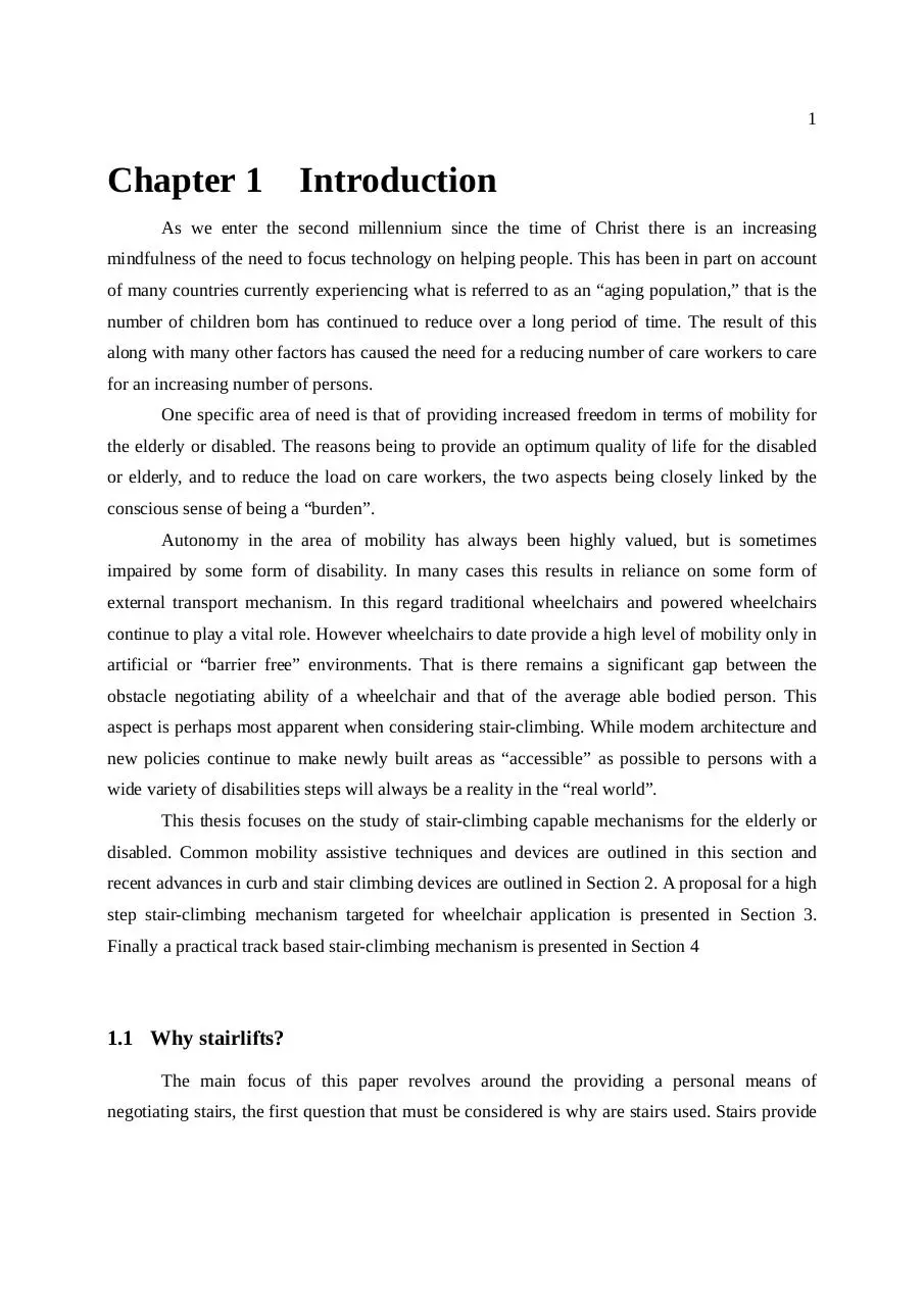
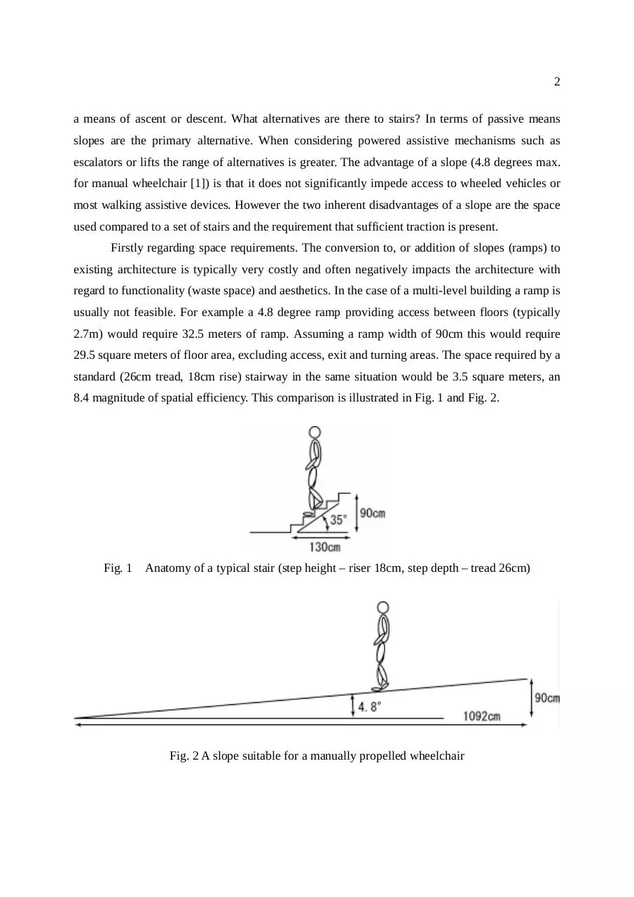
Firstly regarding space requirements. The conversion to, or addition of slopes (ramps) to
existing architecture is typically very costly and often negatively impacts the architecture with
regard to functionality (waste space) and aesthetics. In the case of a multi-level building a ramp is
usually not feasible. For example a 4.8 degree ramp providing access between floors (typically
2.7m) would require 32.5 meters of ramp. Assuming a ramp width of 90cm this would require
29.5 square meters of floor area, excluding access, exit and turning areas. The space required by a
standard (26cm tread, 18cm rise) stairway in the same situation would be 3.5 square meters, an
8.4 magnitude of spatial efficiency. This comparison is illustrated in Fig. 1 and Fig. 2.
Fig. 1
Anatomy of a typical stair (step height – riser 18cm, step depth – tread 26cm)
Fig. 2 A slope suitable for a manually propelled wheelchair
3
Slope or ramp angles can be increased, however 4.8° has been deemed the maximum
angle for negotiation by the average user of a manually propelled wheelchair. In the case of a
powered wheelchair the recommended maximum angle is 7.1°. Local testing of powered
wheelchairs indicated maximum stable climb and descent rates of up to 20°, however the tests
were carried out in ideal conditions on high traction surfaces.
1.2 Stairs - are they safe?
Stairs represent spatial efficiency, and minimum risk in regard to slipping compared to
slopes, however stairs have come to be virtually representative of “barriers”. The term “barrier
free” is increasingly used in a broader context, however the basic concept originated from
reference to an environment that did not impede access to a manually propelled wheelchair.
Major impediments to wheelchair access have been and continue to be consideration for width
and the presence of steps or stairs.
(a) flat
(b) stair descent
(c) stair ascent
Fig. 3 Approximate areas of focus while walking on the flat and up and down stairs
Are stairs dangerous? If so why are they dangerous? Firstly are stairs dangerous, any
movement from any given location to another represents risk. The degree of risk increases with
distance and the presence of any obstacles. In this regard steps or stairs are classified as obstacles,
and therefore represent an increased level of risk or danger. The risk increases with age and or the
presence of mobility or sight related disabilities. Statistics are maintained regarding the level of
risk associated with most forms of public transportation, partially to ensure effort is focused on
4
areas of greatest risk to find means or ways to reduce the risk.
Secondly why are stairs dangerous? In the case of a flat pathway there is some risk that
any given person could fall and injure them self. In the case of stair negotiation careful
recognition of the location of the stair-edge is required. The height of the stair must be estimated,
and finally one’s feet located accordingly. This is illustrated in Fig. 3. Further the person’s shift in
Center of Gravity (COG) becomes complex compared to walking on a flat level surface. Raising
one’s weight to the level of each step takes the leg joint through an angle greater than that
experienced while walking. Weakening leg ability will be most apparent when going from a
seated to standing position, however following this the next most difficult task is often the
negotiation of stairs.
The task of climbing stairs according to basic physics requires more energy than descent,
however the control in stair descent is more difficult. More energy is required climbing stairs but
because the stairs are sloping upwards they are easier to see, therefore easier to negotiate and the
risk of injury in the case of a fall is reduced on account of the reduced potential fall angle. The
fall angle/ height is assumed in the forward direction as this is the direction of travel, falling
rearward is less common, and is often associated with slipping on slippery surfaces.
The task of descending stairs represents effort in regard to control. The visual distance to
the stair is greater, therefore negotiation becomes more difficult. Stair descent is further
complicated by the higher risk of injury in event of a fall on account of the increased fall angle/
height.
The stair inherently represents greater risk of injury on account of the presence of a stair
edge combined with the potentially increased fall angle/ height. The worst case fall angle during
descent on a typical stair (35°) would be 125° (90°+35°) compared with 55° (90°-35°) for stair
ascent.
1.3 Wheeled mobility
The wheeled vehicle has perhaps been one of man’s most important technical discoveries,
early evidence dates back to around 3000 BC. in the Tigris-Euphrates Valley [2], a painting of
early wheels are shown in Fig. 4 [3].
No doubt since early times access to areas with steps would have presented similar
5
challenges as the present day. However in the area of providing personal mobility that is not
significantly limited by terrain the approach employed in early civilization has yet to be rivaled,
that is carriage by a group of two or more persons. While such as the ancient Pharaohs may not
have lacked in personal assistants they did perhaps lack a valid need to be carried from place to
place. The current generation of elderly and disabled do however typically lack in personal
assistants and do have a valid reason to be assisted in the area of personal mobility.
Fig. 4 A painting showing primitive wheels
Picture courtesy of education.eth.net
The approach used by early civilizations has fundamentally not changed in the area of
personal mobility, that is the use of wheeled vehicles in relatively flat environs and carriage by
people or animals in areas not suited to wheeled vehicles.
1.4 Wheels and stairs
(a) mobility scooter tire (b) standard wheelchair tire (c) early wheelchair tire
Fig. 5 Variation of wheel diameter in regard to stair negotiation (tread depth = 26cm)
Stairs perhaps best represent “environs not suited to wheeled vehicles”. The step function
of a stair versus the sinusoidal function of the wheel is illustrated in Fig. 5. Two fundamental
means of stair negotiation are provision of a stepping mechanism, or increasing the wheel’s
6
footprint (diameter) so that the step is in effect bridged. Provision of a stepping mechanism
requires relatively complex mechanical operation and must be linked to knowledge of the
location of the stair edge. Human negotiation of stairs would be categorized as such.
The second basic approach is to in effect increase the forward-rear footprint of the vehicle
so that it bridges the stairs. This can be made possible by increasing the wheel diameter or by
using some form of tracked operation, which in effect emulates a wheel with an infinitely large
radius.
The relative advantages and disadvantages of these two approaches to stair negotiation are
that stepping places weight on the stair’s tread, which is where it is designed to be and involves
no increased risk of slip, that is the risk of slip is no more or less than that on a flat pathway,
however the major disadvantage is it requires knowledge regarding the stair edge. A tracked
approach has the major advantage in that it bridges the stairs and therefore prior knowledge of the
stair-edges is not required. However the major disadvantage is that the vehicle weight rests on the
edge of the stair, this therefore requires stairs to have robust edges, further the track must be
provided with a means to prevent slipping.
Variation of wheel diameter is illustrated in Fig. 5, Fig. 5(a) represents a large scooter or
small powered wheelchair wheel of diameter 30cm. Fig. 5(b) represents the diameter of a
standard manually propelled wheelchair’s rear wheel of 58cm and Fig. 5(c) shows a 1 meter
diameter wheel as used on some early wheelchairs.
1.4.1 Motive force, curb height and wheel diameter
The first simple experiment carried out for the purpose of this study was to gain a
fundamental appreciation for the relationship between “motive force”, “curb height” and “wheel
diameter”.
Fig. 6 Motive force versus curb height and wheel diameter experiment
7
The vehicle used for the experiment was a 3 wheel mobility scooter. Force F(N) was
applied at the rear of the scooter approximately in line with the rear axle as shown in Fig. 6. The
measured force was normalized to fr by dividing the weight (vertical force) measured at the front
axle by the F(N) value. The experimental results are graphed in Fig. 7 for two different tire
pressures. The continuous line on the graph shows the calculated value based on equation 1. The
front tire of the scooter is shown negotiating a 7 cm curb under maximum loading in Fig. 8.
fr = tan cos −1 (
Where
r−h
)
r
(1)
fr = relative motive force
r = wheel radius that is 1/2 the diameter
h = curb height
Fig. 7 Motive force required to negotiate various curb heights for a fixed wheel diameter
It must be noted that equation (1) does not account for any softness in the tire, clearly the
lower tire pressure makes curb negotiation easier, however reduces running efficiency. A relative
force of fr = 1 means motive force (horizontal) equals the weight (vertical force) bearing on the
front tire.
8
Fig. 8 Negotiation of a 7 cm curb by a 20cm diameter tire under maximum loading
In conclusion this experiment showed that the horizontal motive force required to
negotiate a step with a height of half the tire radius was approximately 1.8 times the force bearing
on the tire (vertically), this reduced to 1.4 times for a reduced tire pressure. The maximum step
height negotiated was 0.7 times the tire radius, this required a horizontal force of 2.8 times the
vertical force for a regular tire pressure and 2.2 times for a reduced tire pressure (tire pictured in
Fig. 8). A practical maximum step height negotiable by this tire would be 0.5 to 0.6 times the
tire’s radius.
The simplest way to increase stair climbing ability is to increase the wheel radius. This
and the convenient provision of a manual propulsion mechanism are reflected in modern
manually operated wheelchair rear wheels. However large diameter front wheels are very
awkward in regard to steering. Another aspect that improves stair negotiation is reduced tire
pressure, however this will reduce running efficiency as well as increase stress on the tire,
dynamic control of tire pressure could perhaps fulfill both requirements. A further means of
increasing the step negotiation ability is to actively drive the front and rear wheels (four wheel
drive), therefore assisting the lift component without reducing the drive component, this approach
is employed on modern 4WD scooters – refer to Section 2.2.
An alternative means of increasing effective tire diameter but not tire radius is the use of a
track mechanism, track based mechanisms are outlined in Chapters 2 and 4. The tracks used on
track-based wheelchairs at the time of writing are made of solid rubber, this results in high
pressures exerted on stair edges. Further the knobs provided on the tracks to prevent slipping on
stairs do not necessarily coincide with the stair edges shown in Fig. 58(b). A more ideal approach
9
would perhaps be the realization of pneumatic (tire) tracks, thereby spreading pressure over a
larger area at the point of contact with each stair edge. A deformable track has been proposed in
[4], this is depicted in Fig. 20(a) and (b) and the concept illustrated in Fig. 20(c).
This simple experiment accounted only for static loading considerations, the results of a
study of dynamic considerations for curb negotiation for manually propelled wheelchairs is
provided in [5].
1.5 Requirements for stair-climbing mobility
Climbing a set of stairs presents two central issues, firstly the actual climbing or
negotiating of each single step, and secondly providing stability for the overall mechanism while
on the stairs. In the case of an able bodied person a stepping mechanism is provided in the form
of legs and a very precise balance mechanism is provided by the brain in conjunction with a
variety of sensory systems. The legs are equipped with high speed and high peak power output
actuators in the form of muscles. The brain acts on a combination of visual data (estimation of
stair location and height) and tactile/ pressure sensory data (feedback) from the legs and balance
sensors associated with the ears/ brain, this provides a closed control loop.
Fig. 9 Honda P3 robot negotiating stairs
Photo courtesy of Kidsweb Japan
10
The very complex task of load balancing so as to maintain a correct COG (center of
gravity) during the stair negotiation is carried out almost as a subconscious task. The muscles
provide the high speed and high peak power actuation necessary to correct any sensed error in
balance. This complex task has been emulated in the world of robotics by such as the Honda P3
robot pictured in Fig. 9 [6], control mechanism and algorithms detailed in such patents as [7] and
[8].
Regarding stability orders of magnitude, for a person in a static standing position, forward
– rear stability is in the order of 6°. That is for example in the case of an average height person of
say 173cm, the COG at say 105cm (~waist line) and with a toe to heel load bearing range of say
23cm (actual foot length measurement of say 26cm). This case calculates to give a ~12° range of
stability therefore giving a maximum stability margin of 6° when centered. Worst case static
stability reduces to around 2° (side to side) when standing on one foot. The calculation of
dynamic stability margins during a walking or stair climbing gait is however significantly more
complex.
In order to provide an assistive mobility device suitable for negotiation of stairs a
mechanism capable of negotiating stairs must be provided, two approaches are presented in this
thesis, proposed use of articulated wheel cluster technology and a practical track based
mechanism. Another aspect is the provision of a balance mechanism giving acceptable stability
margins. During stair climbing the provision of acceptable stability at all times is paramount in
regard to safety, and therefore in the public acceptance of any form of stair climbing assistive
device/s. Finally in the case of a wheelchair a constant seat angle is preferred.
The two basic approaches to stability are similar to the modes of stability used in modern
vehicles. Stability may be provided inherently by providing three or more points of contact with
the ground at all times, the common car is such an example. Two points of contact is possible if a
balance mechanism is used as in the case of say a rickshaw (external balance mechanism person), or an internal balance mechanism such as in the case of a bicycle or motorcycle. A
bicycle’s or motorcycle’s internal balance mechanism is the person controlling it, the person
needs only control the vehicle’s lateral motion so as to maintain the appropriate COG (center of
gravity). A single point of contact with the ground is possible also using external or internal
balance mechanisms such as in the case of the common wheelbarrow or unicycle, however in the
case of a single point of contact with the ground both the provision of both front to rear and side
11
to side balance simultaneously becomes a relatively complex task.
Applying the above examples to mobility assistive devices on stairs, four points of contact
with the ground at all times will provide inherent static stability, however it is difficult to achieve
due to the nature of stairs, particularly in regard to the front to rear height differential that occurs.
By using a laterally stable device and employing a personal assistant, or a nearby hand rail to
provide the balance mechanism the problem of front to rear height differential may be resolved,
however the system becomes reliant on the assistant or provision of the right kind of handrails.
The two stair-climbing mechanisms outlined in this thesis are based on the provision of
inherent static stability.
1.6 Common stair-climbing techniques and assistive devices
1.6.1 Assistant based curb, slope and stair negotiation techniques
(a) single person
(b) 4 person stair ascent
(c) 4 person stair descent
Fig. 10 Stair-climbing – current techniques
Two common care-worker/ assistant based approaches to negotiating stairs are shown in
Fig. 10(a) carrying a person on one’s back and Fig. 10(b) and (c), carrying a person in a
lightweight wheelchair. Carrying an elderly or disabled person on ones’ back represents a very
efficient and cost effective approach however it also presents high risk of injury for both persons,
back injury is often associated with long term care – despite using all the “right” lifting
12
techniques, and combined with the risk of suffering a fall [9].
(a) Curb negotiation
(b) Stair descent 3 persons
Fig. 11 Curb and stair negotiation – current techniques
(a) slopes up
(b) slopes down
Fig. 12 Slope negotiation – current techniques
When carrying a person in a lightweight wheelchair the number of assistants may vary
from two to four, depending on the weight of the passenger and the strength of the assistants. It is
recommended that persons being carried in wheelchairs be facing towards the stairs irrespective
of direction of travel, this being to minimize any concerns regarding height and any danger
13
should the passenger slip out of the chair. This is shown in Fig. 10(b) stair ascent and Fig. 10(c)
stair descent. The negotiation of curbs or single steps is possible with a single assistant as shown
in Fig. 11(a), this will also depend on the relative weight of the passenger and strength of the
assistant. The negotiation of slopes is shown in Fig. 12(a) for ascent and Fig. 12(b) for descent. In
Fig. 12(b) the assistant is facing down the slope this is noted as being a matter of personal
preference [10].
1.6.2 Common stair-climbing and van entry assistive devices
Lifts are perhaps the most common means of providing access between floors. Lifts are
typically very expensive and consume significant space. Low cost compact lifts targeted for
residential use however are also available [11]. For negotiation of a small number of stairs for
example the entrance to many western homes (porch) or the high initial step to Japanese homes
(refer Fig. 51) a wide range of electrically or manually operated platforms are available [11][12].
(a) Fixed chair stair-lift
(b) Platform stair-lift
Fig. 13 Assistive devices for stairs and van entry
Photos courtesy of Max-Ability Inc. (a) and garventa.ca (b)
Fixed stair-assist mechanisms broadly fall into 2 categories, the provision of a fixed chair
Fig. 13(a) [11] or a fixed platform Fig. 13 (b) [13] on which a wheelchair and user can board. The
chair or platform is connected to an appropriate railing system customized to suit the stairway it
is designed for. The railing system incorporates some form of cog or pulley mechanism to
provide for motive operation. The rail mechanism also provides for angular compensation to
ensure the chair or platform maintains a constant (level) angle as it follows the stairway.
14
Customization and significant on site work makes fixed stair-assist mechanisms very
expensive and dedicated to a given set of stairs. The chair or platform is usually designed to fold
up to minimize waste space while not in use. The fixed platform is perhaps the most common
stair-assist mechanism used in public areas where lifts are not available. Alternative approaches
include the use of overhead hoists (Section 2.8) Fig. 28(a).
(a) Portable wheelchair lifter platform
(b) Retrofit wheelchair only lift
Fig. 14 Van access mechanisms
Photos courtesy of Sanwa Co. Ltd (a) and americanwheelchairs.com (b)
In regard to assisting wheelchair access to vans a range of portable fold-up ramps are
available [14], portable ramps can also be used for the negotiation of a small number of stairs. Fig.
14(a) shows a manually operated portable lifting platform [15], a more compact wheelchair only
lifter is outlined in Section 2.8 and pictured in Fig. 28(b). A wide range of retrofit type lifters are
available to provide van access for wheelchairs [16]. An electric hoist type wheelchair lifter is
shown in Fig. 14 (b) [14].
Many vehicle manufactures offer a wide range of custom options at the time of new
vehicle purchase. The provision of a seat which swivels out has become an option made available
by most Japanese car manufactures, however the task of transfer to such as a wheelchair remains.
One solution to this problem has been the provision of a seat which doubles as an assistant
operated wheelchair is outlined in Section 2.8 and pictured in Fig. 28(c). The more traditional
option of a built in wheelchair lift is shown in Fig. 15(a) and a built in ramp system Fig. 15(b).
While the built in options provide very elegant solutions they are very expensive and dedicated to
a given vehicle.
15
(a) Wheelchair lifter platform
(b) built in ramp
Fig. 15 Van wheelchair lifts or ramp mechanisms
Photos courtesy of Toyota (a) and (b)
1.7 Stairs - discussion
The presence of stairs in the real world
The presence of stairs will most likely always be a reality in the real world, because of the
high level of spatial efficiency they provide when connecting areas of differing vertical elevations.
Stairs do present an increased degree of danger compared to such as gentle slopes but this must to
some degree by necessity be simply taken into account. For example in the planning of any new
buildings the target users should be considered. Clearly for public amenities, such as wheelchair
users should be considered, but for example in the case of say a private home in Japan where land
space is at a premium (more specifically very expensive) multilevel construction is unavoidable
and stairs will most likely continue to be used. A compromise situation in the case of families
caring for aging parents is often providing all the essential amenities at ground level (barrier free)
and using the upper levels for the younger families’ respective bedrooms etc.
Wheels and stairs
While it is clear that wheels do not relate to stairs well, pneumatic tires do inherently
increase their footprint as the loading on them is increased. The tire pictured in Fig. 8 does look
somewhat overstressed but the crack in the wall of the tire is on account of being well outside the
“use before” date on the tire. The inherent increased footprint limits the pressure exerted on any
16
given point of the stair, particularly the stair edge. In this regard “pneumatic tires” are better
suited than say solid rubber tires to stair negotiation, as well as providing a smoother ride for the
user. The curb negotiating ability of a wheel is mainly related to tire radius and secondarily the
softness (deformability) of the tire. A track based alternative emulates a tire of infinite radius and
is inherently well suited to stairs but the realization of a deformable (soft) track necessary to
provide a stair edge friendly and non-slip tread is difficult.
Assistive techniques or devices
Personal autonomy is regarded highly in today’s society but remains largely unrealized
for mobility disabled persons. Current common practice in regard to stair assistance is that two to
four assistants are required for a mobility disabled person say in a wheelchair to negotiate a set of
stairs. Assistive device based solutions for stair-negotiation include lifts and chair or platform
based stair-lift mechanisms. Wheelchair access to vans can be provided by a portable or built in
ramp, a portable platform lifter or a range of built in or retrofitable lifting mechanisms.
Fixed stair-assist or high step mechanisms
Regarding fixed stair-assist or high step mechanisms, in many cases the provision of such
will be an integral part of the initial design. For example, many vans are dedicated to the
transportation of wheelchair users, and as such the reduction of any potential multipurpose role
would not be of any consequence. However conversion or retrofitting an existing entrance,
stairway or vehicle for wheelchair users is often very difficult and expensive.
1.8 Thesis outline
This thesis focuses on the development of stair-climbing and van access assistive
mechanisms. Chapter one outlined why steps are necessary, safety on stairs, how wheels relate to
stairs, the requirements for stair-climbing and current common approaches or devices used to
mobilize elderly or disabled persons in “barrier present” environments.
Chapter 2 outlines recent advances in mobility assistive mechanisms available at the time
of writing. The main focus is on curb negotiation, stair-climbing, and high step assistive devices.
High steps are noted as being common in the boarding of such as a van and in the case of Japan
17
the first step to most traditional Japanese homes.
Chapter 3 outlines a proposal for a high step capable stair-climbing mechanism targeted
for wheelchair application. The mechanism is based on a chair connected to respective front and
rear clusters of wheels. The front and rear wheel clusters are then connected to the chair base via
two controlled articulated links. The unique functionality provided include stair negotiation in the
desired direction of travel and the ability to directly enter such as a van or Japanese home without
the need for any special equipment.
Chapter 4 outlines the development of a very practical stair-climbing mechanism based on
dual section track operation. The stair-climbing wheelchair was trailed on the slopes of Nagasaki
and having found favor with the locals has been made commercially available. The two section
track mechanism provides a robust and reliable means to negotiate highly irregular stairs with
relative simplicity. The prototyping of a guidance and control system for the track based
wheelchair is outlined.
Chapter 5 provides an overall discussion and concluding remarks.
18
Chapter 2 Recent advances in mobility assistive
devices for stairs or curbs
This Section provides an overview of recent advances in mobility assistive devices
available for curbs or stairs at the time of writing. The coverage focuses on the curb or stair
climbing ability of the devices.
2.1
Curb assistive mechanisms for wheelchairs
(a) Additional wheel illustration
(b) additional wheel photo
(c) Curb catcher illustration
Fig. 16 Curb assistive mechanisms
Photo courtesy of Shoprider (b)
z
z
Features
-
Raises the curb negotiating ability of a wheelchair’s front wheels
-
Retrofitable to a wide range of manually propelled and powered wheelchairs
-
Low cost
-
Light weight
Negative points
-
Increased frontal area required for turning (additional wheel only)
-
Cannot operate backwards (curb catcher only)
-
Not available for or compatible with all types of wheelchairs
19
z
Comments
At the time of writing a number of curb assisting devices are available for manually
propelled and powered wheelchairs. One such device provides additional wheels mounted on the
front wheel caster assemblies [17]. The additional wheels are positioned a little forward and
higher than the wheelchair’s casters so as to hit the curb first and raise the front of the wheelchair
and enable easier negotiation of curbs. This is illustrated in Fig. 16(a) and depicted in Fig. 16(b).
Another device is the positioning of a hinged curb catcher as shown in Fig. 16(c). The curb
catcher hits the curb and rotates as shown by the dotted line resulting in lifting the front of the
wheelchair enabling negotiation curbs.
2.2
Curb capable powered wheelchairs and mobility scooters
(a) 150mm curb wheelchair
(b) 120mm curb 4WD scooter
Fig. 17 Curb capable mobility assistive devices
Photos courtesy of A1 mobility (a), and Serio-Japan (b)
z
Features
-
High curb negotiating ability (150cm powered wheelchair/ 120cm mobility scooter)
-
High level of mobility in most environments
-
High level of stability (cf. manually propelled wheelchair)
-
Easy to operate (mobility scooter only)
20
z
Negative points
-
Large turning circle (mobility scooter only)
-
Joystick operation difficult (powered wheelchair only)
-
Heavy (therefore very difficult to assist with stairs or van entry without special
equipment)
z
Comments
Persons with limited upper limb ability have traditionally used such as a fully powered
wheelchair, however the task of controlling a powered wheelchair is relatively difficult and
research continues toward simplifying this task refer to [18]-[21]. The powered wheelchair shown
in Fig. 17(a) [22] is designed to negotiate curbs up to 150mm, the front wheels (anti-tip device)
are adjustable in height and are raised when curb negotiation is required. Mobility scooters such
as that shown in Fig. 17(b) [23] have become increasingly popular for both elderly and disabled
persons, part of the reason for increased popularity is they are easier to control compared to the
powered wheelchair and seem to have gained greater acceptance by the public compared to the
powered wheelchair. While both powered wheelchairs and mobility scooters provide excellent
general purpose mobility their weight makes assistance with stairs or van entry without special
equipment very difficult. A wide variety of lifting mechanisms are available, however at
significant cost and tradeoff in terms of space etc (refer to Sections 1.6.2 and 2.8).
(a) TAQT wheelchair
(b) TAQT principle of operation (c) TAQT spring wheel close up
Fig. 18 Terrain-Adaptive Quadru-Track (TAQT) based wheelchair
Photos and illustration courtesy of Shigeo Hirose
21
A 4WD mechanism provides improved curb negotiation compared to 2WD (2 wheel
drive) operation, however a 4WD mechanism is not well suited to stairs for 3 fundamental
reasons. Firstly the lack of necessary traction, secondarily the change of vehicle angle during the
stair climb reduces the vehicles stability to unacceptably low levels and finally in the case of a
vehicle propelling a person such as a wheelchair the seat angle should ideally remain relatively
constant. A prototype mechanism dealing with all of these issues is outlined in [24]. The
Terrain-Adaptive Quadru-Track (TAQT) based wheelchair prototype is pictured in Fig. 18(a), the
principle of COG modification illustrated in Fig. 18(b) and a close up of a wheel (spring loaded)
gripping a stair edge is shown in Fig. 18(c).
2.3
Track based stair-climbers
(a) Autonomous stair-climbing wheelchair
(b) Stair-climbing wheelchair transporter
Fig. 19 Modern single track based stair-climbers
Photos courtesy of Hospimedica group
z
Features
-
Stair-climbing ability
-
Autonomous stair-climbing possible (autonomous stair-climbing wheelchair only)
-
Suitable to most outdoor stairs and some indoor stairs
-
Simple operation (cf. non-track based stair-climbing mechanisms)
22
-
Provides stair-climbing ability for standard wheelchairs (transporter only)
-
Provides for general purpose off stair operation (autonomous stair-climbing
wheelchair only)
z
Negative points
-
Must climb stairs backwards
-
Special mechanisms required for off stair operation and changing to and from
stair-climb angle
-
Non slip mechanism required when on stairs (tread/ knobs), asynchronism between
stair edges and tread/ knobs results in high non linear pressures exerted on stair
edges
z
-
Unsuitable for most indoor stairs and some outdoor stairs
-
Heavy (cf. standard power wheelchair - autonomous stair-climbing wheelchair only)
Comments
Tracked climbers are dealt with in more detail in Section 4. A modern single tracked fully
autonomous stair-climber and powered wheelchair is shown in Fig. 19(a) and a platform used to
carry a wheelchair and user up or down stairs is shown in Fig. 19(b) [25]. An older technology
single track stair-climber is shown in Fig. 62 (powered stair-climber – free wheeling on the flat)
and Fig. 64 (tracked stair-climbing wheelchair transporter operating at a station in Japan). The
central advantage of the use of tracks is the independence or robustness regarding the type of stair
or surface being negotiated. Disadvantages of track based operation include the high pressure
exerted on the stair edges therefore limiting use to stairs with appropriately robust leading edges.
An anti-slip mechanism is required while on the stairs and a mechanism is required to ensure the
device changes to and from the stair angle in a controlled manner at the top of stairs.
Regarding the most fundamental track based problem, that of the high pressure exerted on
the stair edges a deformable track has been proposed and modeled in [4]. The track consists of
deformable or hysteresis blocks configured as shown in Fig. 20(a). The principle of operation is
shown in Fig. 20(c), namely to spread the stair edge load over a larger area as well as inherently
provide a means to prevent slipping that is not reliant on the track tread (knobs) synchronizing
with the stair edges. This compares with a regular wheelchair track as depicted in Fig. 58(a),
illustrated in Fig. 58(b) and discussed in Chapter 4.
23
(a) XEVIUS tracks
(b) XEVIUS track close up (c) XEVIUS track principle
Fig. 20 Xero-Viscous Upstair Service (XEVIUS) deformable tracks
Photo and illustration courtesy of Shigeo Hirose
2.4
Lightweight wheelchair stair-climbing attachments
(a) Stair-climb mech. (b) Mech. attached to wheelchair
(c) Stair-climbing operation
Fig. 21 Scalamobile – stair-climbing attachment
z
Features
-
Stair-climbing ability
-
Suitable to almost all stairs (max. step height up to 25cm Scalamobile/ 21cm C-max )
-
Compact
-
Uses existing wheelchair – no transfer required (Scalamobile only)
-
Lightweight (~25Kg plus wheelchair Scalamobile/ ~32Kg total C-max)
24
z
Negative points
-
Requires special instruction regarding usage (Scalamobile only)
-
Dedicated assistant operated wheelchair – transfer required (C-max only)
-
Orbital motion tends to be uncomfortable for passengers (Scalamobile)
-
Auto-brake mechanism does not suit roughly surfaced stairs
(a)
(b)
(c)
(d)
(e) Automatic brake
Fig. 22 Scalamobile – principle of operation (a)-(d), automatic brake (e)
Illustration (a-d) courtesy of Max-Ability Inc.
(a) C-max stair-climber
(b) stair edge brakes
(c) climber operation
Fig. 23 C-max articulated lifting mechanism based stair-climbing wheelchair
Photos courtesy of Alber
25
z
Comments
The addition of stair-climbing functionality by necessity increases a wheelchair’s weight,
however by making this functionality modular and easily removable from the wheelchair it can
be attached only when required (Scalamobile) Fig. 21 [26]. Two pairs of wheels operate on
separate axes, the orbiting motion is shown in Fig. 22(a)-(d). The C-max wheelchair operates in a
similar manner to the Scalamobile except one pair of wheels is replaced with lifting protrusions
as shown in Fig. 23(c). The respective stair edge auto brake mechanisms are pictured in Fig.
22(e) and Fig. 23(b).
The stair-climber described in Section 4 and pictured in Fig. 66(c) technically qualifies as
a stair-climbing attachment. This stair-climber (KSC-C-10) has been developed by Kyowa
Industries [27] in conjunction with Nagasaki University and associated research groups [28]. The
operation is smooth and easy to operate. However the size and weight of the stair-climbing unit is
much greater than such as the Scalamobile or C-max.
2.5
Wheel cluster based stair-climbers
(a) three wheel cluster
(b) four wheel cluster
Fig. 24 Powered single cluster stair-climbers
Photos courtesy of Hospimedica group and runsoft.com.cn
26
z
z
Features
-
Stair-climbing ability
-
Suitable to almost all stairs
-
Compact
-
Operate as general purpose powered wheelchairs
-
Lightweight (cf. track based wheelchairs)
Negative points
-
Requires assistance (one person) for stair operation
-
Orbital stair-climbing operation may be uncomfortable for passengers
(a) barrier free mode
(b) stair-climb configuration
Fig. 25 Wheel cluster based stair-climber with articulated balancing sliders
Illustrations courtesy of US Patent 6,484,829 B1
27
z
Comments
Wheel clusters in their simplest form adapt the most common means of transportation
“the wheel” to the most common obstacle to the wheel “the stair”. If a single wheel cluster is
used, a balancing mechanism is required for any form of stair-climbing. The term “Single wheel
cluster” in this paper refers to the lateral configuration of 2 identical clusters of wheels. Operation
on stairs is similar to the Scalamobile as shown in Fig. 21(c), except the stair-climbing equipment
is an integral part of the wheelchair, the models pictured in Fig. 24 also operate as standard
powered wheelchairs, 3 wheel cluster Fig. 24(a) [25] and 4 wheel cluster Fig. 24(b) [29]. Fig.
24(b) differs in operation in that it uses four cluster wheels for barrier free operation, that is there
are no auxiliary front wheels or casters. A variation to the single cluster stair-climber is detailed
in [30], this mechanism is illustrated in Fig. 25 in barrier free and stair-climb modes respectively.
The mechanism provides articulated front and rear sliders to maintain balance during stair
negotiation therefore enabling autonomous stair-climbing operation.
2.6
COG modification wheel cluster based stair-climber
(a) barrier free mode
(b) standing mode
(c) hand rail assisted stair-climb
Fig. 26 COG modification stair-climber
Photos/ illustration courtesy of John Williamson (a) and (c), US patents 6,443,250 B1 (b)
28
z
Features
-
Stair-climbing ability suitable to almost all stairs
-
Autonomous stair-climbing operation possible
-
Standing mode provided for eye level communication with standing persons and
access to top shelves
-
Compact (cf. track based mechanism)
-
Operates as a general purpose powered wheelchair
-
Operates in almost all environments including sand, gravel, highly irregular surfaces
and slopes up to ~25° (surface permitting) in the direction of desired travel
z
z
Lightweight (cf. track based wheelchairs)
Negative points
-
Requires assistance (one person) or appropriate hand rail/s for stair operation
-
Must climb stairs backwards
-
Expensive ($29,000 US as at Nov 21 2002)
-
May be require prescription and special training (US FDA recommendation)
-
Orbital stair-climbing operation may be uncomfortable for passengers
-
Concern regarding balancing mechanism
Comments
In the case of a wheelchair with CM (COG modification) an appropriately located
hand-rail can be used by the operator (user) to provide commands for the balancing mechanism,
alternatively operation by and assistant similarly to that shown in Fig. 21(c). Fig. 26(a) shows the
iBOT™ 3000 wheelchair [31] [32] in barrier free mode, only the rear wheels make contact with
the ground using the front casters to provide free wheeled steering. All four rear wheels are used
to provide extra traction 4WD making operation on sand, gravel or unleveled surfaces possible. A
standing mode illustrated in Fig. 26(b) is provided, by balancing on two wheels eye to eye
contact with standing persons is possible as well as the reaching of upper shelves. Fig. 26(c)
shows the stair-climbing operation, if a handrail is appropriately provided the user can negotiate
the stairs unassisted. In the case of appropriate handrails not being available an assistant (person)
is required. Autonomous operation on stairs using a single handrail is also possible.
29
2.7
Dual wheel cluster stair-climber
(a) barrier free mode
(b) stair-climbing mode
Fig. 27 Dual cluster – front articulated stair-climber, “Freedom”
Photos courtesy of Tomo Co. Ltd and Tamagawa University
z
z
z
Features
-
Stair-climbing ability suitable to most standard stairs
-
Autonomous stair-climbing operation possible
-
Operates as a general purpose powered wheelchair
Negative points
-
Must climb stairs backwards
-
Orbital stair-climbing operation may be uncomfortable for passengers
-
Large (width 820mm cf. standard powered wheelchair)
-
Heavy (100Kg cf. standard powered wheelchair)
Comments
A dual cluster – front articulated stair-climber, “Freedom” is shown in Fig. 27 [33]. This
wheelchair operates as a standard powered wheelchair when configured as shown in Fig. 27(a),
30
using the rear wheels for drive and front freewheeling casters. The configuration is changed as
shown in Fig. 27(b) for stair-negotiation. Stair-climbing is forward down and back up. The front
cluster rotates passively during stair-negotiation.
2.8
Miscellaneous stair-assist and van entry mechanisms
(a) Overhead wheelchair hoist (b) Portable wheelchair lifter
(c) Seat lift/ wheelchair
Fig. 28 Miscellaneous assistive mechanisms for stairs and van entry
Photos courtesy of Outa Co. Japan (a) Toyota (b) and (c)
z
Features
-
Stair-climbing ability suitable to most standard stairs (overhead wheelchair hoist [34])
-
Van access for most wheelchairs and passenger possible (portable wheelchair lifter
and seat lift/ wheelchair [35])
-
Van provided with built in dedicated seat/ wheelchair lifter (seat lift/ wheelchair)
-
Van seat operates as a general purpose operator assisted wheelchair (seat lift/
wheelchair)
-
Wheelchair lifter is lightweight and portable (portable wheelchair lifter)
31
z
Negative points
-
Expensive and dedicated to a single set of stairs (overhead wheelchair hoist)
-
Lifting of standard manually propelled wheelchair not supported (seat lift/
wheelchair)
z
Powered wheelchairs not supported (portable wheelchair lifter)
Comments
The provision of a seat which swivels out has become an option made available by most
Japanese car manufactures, however the task of transfer to such as a wheelchair remains. One
solution to this problem has been the provision of a seat which doubles as an assistant operated
wheelchair shown in Fig. 28(c) [35].
2.9
Recent advances in mobility assistive devices for stairs or
curbs, summary and discussion
Table 1 provides a broad categorization of curb or stair assist mobility enhancement
devices available at the time of writing.
Stair-climbing wheelchairs rated as highest risk devices
Stair-climbing wheelchairs are currently rated as highest risk devices “Class III”
alongside such as pacemakers (USA FDA.). Class III are defined generally as “life sustaining or
life supporting, implanted in the body, or present an unreasonable risk of illness or injury.”
Furthermore the functionality they provide (stair-negotiation) is not considered necessary, rather
such functionality is considered as “luxury.” In light of such attitudes at government levels (UK,
USA. etc.) the progress in regard to stair-climbing mobility has been/ is understandably slow.
Change to and from stair-angles
In regard to autonomous stair climbing vehicles the phases requiring greatest care are the
entering or exiting of a stair climb at the top of a set of stairs. This usually requires the careful
synchronizing of the mechanism’s change of angle and change of angle of the chair base in a
32
controlled manner. That is, to avoid a sudden and uncontrolled tilt from a level angle to the stair
angle (typically 35°) or visa versa.
Table 1 Broad categorization of curb or stair assist mobility assistance devices
Device
Advantages
Curb assistive mechanism Higher
curbs
possible,
for wheelchairs Fig. 16.
retrofitable,
low
cost,
lightweight.
Curb capable powered Excellent overall mobility in
wheelchairs and mobility most environments including
scooters Fig. 17.
curb negotiation.
Track based stair climbers Simple autonomous operation on
Fig. 19
stairs and/ or steep slopes
possible. Operation as a standard
wheelchair to some extent
possible.
Lightweight
wheelchair
stair-climbing attachments
Fig. 21 and Fig. 23
Wheel
cluster
based
stair-climbers Fig. 24
COG modification wheel
cluster based stair-climber
Fig. 26
Dual
wheel
cluster
stair-climber Fig. 27
Misc. overhead wheelchair
hoist Fig. 28(a)
Misc. portable wheelchair
lifter Fig. 28(b)
Misc. seat lift/ wheelchair
Fig. 28(c)
Stair-climbing possible on most
stairs with only one assistant,
compact, lightweight.
Stair-climbing possible on most
stairs with only one assistant,
relatively compact. Operation
similar to standard powered
wheelchair possible.
Excellent overall mobility in
most environments including on
sand, gravel and stairs with little
or no assistance.
Autonomous
stair-climbing
possible. Operation as a standard
wheelchair to some extent
possible.
Suitable to most stairs. Suitable
to most wheelchairs.
Van access for most lightweight
wheelchairs and passenger.
Portable, lightweight, low cost.
Van access for dedicated seat/
wheelchair and passenger.
Disadvantages
More turning space required, not
compatible with all wheelchairs.
Additional weight makes assistance
with stairs difficult, special provision
required for entry to such as a van.
Only suits stairs with robust edges,
typically not well suited to general
purpose operation. Heavy, special
provision required for entry to such
as a van. Must negotiate stairs
backwards.
Special training for assistant may be
required. Orbital motion tends to
passenger discomfort.
Orbital motion may cause passenger
discomfort.
Special
provision
required for entry to such as a van.
Concern
regarding
balancing
mechanism.
Special
provision
required for entry to such as a van.
Must negotiate stairs backwards.
Heavy, wide, special provision
required for entry to such as a van.
Must negotiate stairs backwards.
Expensive, dedicated to a single set
of stairs.
Powered wheelchairs not supported.
Transfer required if a manually
propelled wheelchair is used.
This controlled tilt function is provided by the assistant in the case of single assistant
mechanisms. However in the case of the single assistant mechanisms outlined in this section the
maintenance of a constant seat angle is not possible. The seat angle is determined by the centred COG,
33
that is, in the case of a single wheel cluster based mechanism the assistant must constantly alter the
wheelchair angle to counter the shifting COG. The provision of a mechanism to counter this COG
shift, as well counter the orbital motion inherent would be desirable for both passenger comfort and
safety. Some of the wheel cluster based mechanisms use solid rubber tyres, as noted in the previous
section they tend to be less comfortable for the passenger and are prone to breaking (Scalamobile).
The choice of solid rubber tires is assumed to reduce the size of the mechanism as well as increasing
stability.
Scalamobile in Nagasaki
The Scalamobile (Section 2.4) has been used in Nagasaki for some years but noted to be
quite uncomfortable for the person being carried and difficult to use. Special training is required
for operators. Specific problems encountered on the slopes of Nagasaki were the automatic brake
shown in Fig. 22(e) automatically locks the wheels when it drops over the front of a stair,
however on roughly hewn or cast concrete stairs the brake often cuts in during use making
operation very awkward. The inherent operator difficulty is partially being able to time the
wheelchair to arrive at the edge of the stair for the next cycle illustrated in Fig. 22(a)-(d), and
partially the inherent COG shift that occurs during the stepping cycle. The discomfort in being
carried is the inherent oscillation that occurs on account of the orbital motion produced from the
mechanism during stair climb. It must however be noted the orbital or stair-climbing speed is
adjustable, therefore operating at a slower does reduce this. As with many such devices operator
skill is central in providing user comfort.
COG modified wheel cluster based stair-climber
The iBOT™ 3000 perhaps represents the most advanced all purpose stair-climbing
mechanism at the time of writing. US government approval gained Nov 21 2002, FDA advisors
urged a few limitations namely to ensure patients can use the complex technology safely, a
doctor's prescription and special training to operate it [36].
Regarding the choice of mobility assistive solutions
In regard to the overall issue of mobility assistive devices typically a range of options are
available for any given disability, that is there is significant overlap. The choice of “best fit” will
be influenced to some degree by the perceived social acceptability in any given culture at any
34
given time. Further preference may be influenced by personal experience, for example negative
experiences or impressions of people who used this or that mobility assistance device [37]. It is
largely the role of the “occupational therapist” (OT) to discern which device and or approach is
best suited to any given individual. The decision must also by necessity reflect the longer term
direction in which the disability is moving, whether the condition is expected to improve, be
stable or degenerative.
Summary
This section outlined recent advances in mobility assistive devices for stairs assist and
high step mechanisms available at the time of writing. A number of functions are not provided by
any mechanisms to date. The highest curb or single step negotiable is 150mm, however entrance
to a van or to a traditional Japanese home represent high single steps ranging up to about 75cm in
height. Further all stairs climbing mechanisms ascend stairs in reverse. Clearly operating a
vehicle in the direction of desired travel represents a more logical mode of operation. A solution
to these and other problems is proposed in the following section “Proposed high step and
stair-climbing mechanism.”
35
Chapter 3
3.1
Proposed high step and
stair-climbing mechanism
Stairlifts uk
The previous chapter outlined curb or stairlift capable mechanisms available at the time
of writing.
However
for
mobility
in
the
real
world
significant
gaps
remains
between the functionality required for autonomous mobility and the functionality
provided by currently available mobility devices.
This chapter focuses on the proposal of a mechanism optimized for wheelchair use and
targeted at overcoming a number of shortcomings in wheelchairs with regard to operation in
barrier present environments - refer to chapters 1 and 2. Specifically the high single step
functionality necessary to directly board such as a van or entry to a Japanese home with no
special equipment.
At the time of writing no mobility assistive device facilitates the direct boarding of a van
or access to such as a traditional home (high initial step) without the aid of special equipment
and/ or assistance. Furthermore no mobility assistive device facilitates the negotiation of stairs in
the desired direction of travel which represents a logical mode of operation.
3.2
Proposed mechanism
The proposed mechanism’s operation in barrier free environments, that is relatively flat
areas, is based on the use of 4 wheels much the same as a standard powered wheelchair. The rear
wheels are independently powered and the front wheels are free-wheeling casters. By
independently controlling the rear wheels steering is achieved.
However in order to negotiate stairs and high steps such as entrance to a vehicle or to a
Japanese home additional mechanisms are provided. The rear wheels used in barrier free mode
are 2 wheels of a 4 wheel cluster of wheels. By rotating the wheel cluster stairs can be negotiated,
refer to Section 2.4 regarding cluster based operation. The front wheels used in barrier free mode
are not used for stair climbing, rather a front cluster of 4 wheels take over from the front
free-wheeling wheels to provide the front of the mechanism with stair negotiating ability. Finally
36
both front and rear wheel clusters are connected to the chair base via two controlled linkages so
as to permit the wheel clusters to be able to negotiate stairs and ensure the chair base angle
remains constant.
The mechanism configured for barrier free operation is illustrated in Fig. 29(a),
stair-climbing operation is illustrated in Fig. 29(b). Operation in barrier free areas is proposed to
be identical to that of a standard powered wheelchair, however by necessity in the negotiation of
obstacles such as stairs some low level assistance is required, for example the selection of mode
of operation such as: vehicle alight, vehicle disembark, stair negotiate, additional traction or
simply “stand” (high shelf or eye level contact with a standing person).
Rise = 18 cm
Tread = 26 cm
Angle = 34.7o
(a) side elevation barrier free mode
(b) side elevation stair climb mode
Fig. 29 The high step stair-climbing mechanism
3.3
Modeling process
The modeling process consists of two major parts, that is Numerical modeling to confirm
geometric feasibility particularly regarding the leg actuators, and the building of a scale model to
confirm three dimensional practicality and to some degree understand the controllability. Detail
37
regarding the scale model is provided in Appendix B.
3.3.1
Numerical model
Numerical modeling begins with proposal of a target specification. This is followed by the
specification of geometric parameters that meet the target specifications. An analysis is provided
regarding the linear leg actuators and finally an analysis of stability margins is provided. Target
specifications for the high step stair-climbing mechanism are listed in Table 2.
Table 2 High step stair-climbing mechanism target specifications
*1
*2
Item
Specification
Maximum continuous stair-climb angle
Maximum step height
Minimum step tread
35° standard (45° - max*1)
200mm
200mm
High single step
750mm*2
Maximum slope angle
25°*3
Stair-climb speed (max.)
20 steps per minute (1 step/ 3 sec.) *4
Stair descent speed (max.)
20 steps per minute (1 step/ 3 sec.) *4
Speed on the flat (max)
8 km/h
Operating range (time)
Barrier free operation
Stair operation
140 minutes continuous operation
50 minutes continuous operation
Size length, width, height
1,150*5x550x900mm
Seat height
Barrier free operation
Stand mode (max)
450mm
1,250mm*6
Power source (battery)
12V 35Ah x2
Drive motors (primary drive)
24VDC 208W x2
Vehicle plus battery weight
130Kg + 30Kg = 160Kg
Max. passenger weight
80Kg
Any angle over 35° will be reflected in the seat angle, that is the seat angle is normally
set at a -6° (backward) lean, a stair angle of say 38° will alter this lean angle to -9° for
ascent and -3° for descent and in worst case a 45° stair would result in a -16° (backward)
lean for ascent and +4° (forward) lean for descent.
High single step 750mm, in the case of a high single step the landing must provide at
38
*3
*4
*5
*6
least 1,000mm of landing space. In the case of the high step including a regular final
step as is the case in many Japanese entrances the final step must not exceed 200mm in
height or 450mm in depth refer to Fig. 51.
Under ideal tractive conditions, derating required in case of wet and/ or slippery
conditions. Seat angle remains constant, assumes use of barrier present mode.
Assumes synchronous operation, refer Sections 3.4 and 3.5.
Vehicle length assumes footplates are folded down, this reduces to 1,000mm when the
foot plates are folded up.
Level surface assumed for maximum standing height.
(a) Rear mechanism
(b) Front mechanism
Fig. 30 Geometric model of rear and front mechanisms
Fig. 30 shows the geometric orientation of the rear and front articulating mechanisms
respectively and the wheel clusters. Table 3 provides information regarding the geometric
parameters, link lengths, articulating ranges etc.
The front wheel cluster’s range of operation is illustrated in Fig. 31, part of the potential
operating range is blocked and labeled accordingly. The limited range of operation, that is
blocked area, is due to interference between the front casters and the front cluster drive motor.
However even if this limitation was resolved the front cluster axle would interfere with the foot
plates. This interference limits the stair-hugging ability of the mechanism during stair climb, that
is resolution of this point of interference would permit the mechanism to operate closer to the
stairs in the ascent phase and therefore enhance stability as well as reducing concern regarding
the height of the mechanism. The rear wheel cluster’s range of operation is illustrated in Fig. 32.
39
Actuated leg range angles are indicated based on 0° when fully retracted (folded up).
Table 3 High step stair-climbing mechanism geometric parameters
Description
Notation
Measure
Operating range (angle)
Offset (angle)
Wheel radius
r
12.5cm
Cluster spacing
d
30cm
Rear leg upper link
l1
74.5cm
126°
10° (U=0°)
Rear leg lower link
l2
58.4cm
126°
22° (L=0°)
Front leg upper link
l4
62.4cm
76°
96.5° (U=0°)
Front leg lower link
l5
57.7cm
70°
21° (L=0°)
52.2cm
(assumes chair @ -6°
angle, on level surface)
61°
Front to rear
Reference
(x, y )
( x 4, y 4 )
rear
front
Lower actuator
retracted
extended
U=0o
Fully retracted
U=0o L=0o
Blocked
area
Upper actuator retracted
extended
U=0o L=70o
U=76o
Front cluster
operating range
U=76o L=70o
Fig. 31 Front wheel cluster articulation mechanism and operating range
40
U=0o L=126o
U=0o
Lower
actuator
retracted
extended
Rear cluster
operating range
Fully retracted
U=0o L=0o
Upper actuator
retracted
extended
U=126o L=0o
U=126o
U=126o L=126o
Fig. 32 Rear wheel cluster articulation mechanism and operating range
3.3.2
Linear actuator power calculations
The linear actuators were modeled based on recent availability (at the time of writing) of
low cost (~¥25000, ~$200US), lightweight linear power actuators (Max. 6000N, 5mm/sec no
load, 3mm/sec max. load, 24v, weight 2.5 kg, duty cycle 10%).
The low duty cycle (10%) is acceptable in that the linear power cylinders are only
required when changing climb phases, for example barrier free mode to stair-climb mode. In the
case of continuous or intermittent stair-climb or descent only the wheel cluster rotation motors
and drive motors are required. Linear actuator operation is only required when the average stair
pitch changes, or in the case of front-rear cluster asynchronous operation. In contrast the wheel
cluster rotation motors would require a much higher duty rating (closer to 100%).
Calculation of the output power required by the linear actuators is made with reference to
Fig. 33. The linear actuator output requirements have been calculated in two basic stages. Firstly
the actuator torque applied to the respective leg as a function of leg angle is calculated. A fixed
41
lifting value is then assumed and the required actuator output power is calculated. This
calculation is based on the kinematics of the upper and lower linkages with regard to vertical.
In order to simplify the calculation as far as possible the output is assumed at the center of the
wheel cluster, and all mechanical losses, friction, stiffness etc. are neglected.
(x1,y1)
lah
Θ2
l2
lao/p
l1
Θo
lbb
lb
Θ1
lc
Θbc
(x2,y2
y2)
2)
Θ3
Θab
a
lb
lb
lbt
y
(x,y)
x
(a) output to the wheel cluster
(b) actuator output to the leg (upper)
Fig. 33 Calculation of linear actuator output power (rear leg)
The position of ( x 2, y 2 ) shown in Fig. 33(a) is calculated as follows:
x 2 = l1 Sinθ 1 + l 2 Sin(θ 2 − θ 1)
(2)
y 2 = l1Cosθ 1 − l 2 Cos (θ 2 − θ 1)
(3)
θ 3 = Tan −1 ( y 2 x 2)
(4)
l3 = y 2 Sinθ 3
(5)
NB. All θ values consist of a leg angle value “U” for Upper leg angle and “L” for lower
42
leg value and an offset component which relates the leg angle to a vertical reference in the case of
the upper leg and to alignment with the upper leg in the case of the lower leg. Offset values and
lengths relating to equations (2)-(5) are as follows:
θ 1 offset value 10° at U= 0°
θ 2 offset value 22° at L= 0°
l1 length 74.5cm
l 2 length 58.4cm
The output torque applied in this case to the rear leg (upper) can be related to actuator
output illustrated in Fig. 33(b), and can be calculated as follows:
lah = lc Sinθbc
(6)
lbt = lc Cosθbc
(7)
lbb = lbt − lb
(8)
The actuator output position lao / p is thus given by
lao / p = lbb 2 + lah 2
θab = 180 − Cos −1 (lbb lao / p )
(9)
(10)
The actuator’s angle of incidence θ 0 to the leg is given by
θ 0 = 180 − θbc − θab
The torque at ( x1, y1) denoted T ( x1, y1) can be calculated from
(11)
43
T ( x1, y1) = P 0 lc Sinθ 0
l1
(12)
where P 0 is the actuator’s mechanical output power (kgf/cm). The resultant lifting
capability to the wheel cluster center can be expressed as
Plift = P 0 lc Sinθ 0
l3Cosθ 3
(13)
where Plift represents the resultant vertical lift component at the wheel cluster center. As
the lift component is fixed in this case 80Kg (refer to following Section on stability margins) the
expression is rearranged to give the required actuator output power for any given configuration of
the legs. This is expressed as
P 0 = Plift l3 Cosθ 3
lc Sinθ 0
(14)
In applying this to the lower actuator the expression is altered to
P 0 = Plift l 2 Cos (θ 2 − θ 1)
lc Sinθ 0
(15)
where lc and θ 0 refer to the lower actuator’s parameters. Fig. 34 shows the calculated
actuator output requirements for each actuator. This data is based on the front and rear wheel
clusters following a near linear trajectory from a barrier free orientation to the rear leg orientation
shown in Fig. 38 and front leg orientation shown in Fig. 43. The leg angle data was measured
from a calibrated 2D paper model and then calculations made as per formulae (2) to (15).
The kinematical orientation of each actuator was optimized based on five main
constraints. Firstly a peak output of 600 kgf/cm (~6000N) was assumed. Secondly, the overall
size of the wheelchair must not exceed that of a standard powered wheelchair. The seat height (in
barrier free mode) must match that provided by a standard wheelchair (~45cm). The front and
rear leg operating envelopes must facilitate negotiating a 35° set of stairs forward up and
forward down with no change in chair angle and finally be able to negotiate a single step e.g.
44
vehicle entry of up to 75cm (forward up - back out).
Fig. 34 Required linear actuator power outputs vs. respective wheel cluster extensions (leg
extending at 78° outwards with respect to horizontal)
Fig. 35 Actuator extension vs. respective wheel cluster extensions (leg extending at 78° outwards
with respect to horizontal)
45
With reference to Fig. 34 the peak output appears to be exceeded at 2 points. Firstly the
rear leg lower actuator exceeds the 600kgf/cm for the first 20cms of operation, however with
reference to Fig. 35 which shows “actuator extension,” operation is not required during this phase.
In the case of the front leg upper cylinder the first 5cm of operation simply lowers the front wheel
cluster to the ground in order to take over from the free wheeling casters, therefore no output
power is required during this phase. Peak outputs only occur during the first few seconds of
reconfiguration from barrier free mode and at maximum reach in the case of the rear mechanism.
3.3.3
High step stair-climbing mechanism stability margins
In the design of any assistive device safety is central. Fig. 36 and Fig. 37 show worst case
stability analysis with regard to stair ascent and descent respectively. The analysis is based on
assumed lumped centers of mass as shown. A user weight of 40 to 80 kg is considered. The effect
of reconfiguration of the upper legs and cylinders is not considered significant compared with the
wheel cluster units.
User = 40~80kg
8 g
Total system (80kg user)
ser) 220kg
2
Total system (40kg user) 180kg
1
g
Front wheel
e
cluster unitt 20kg
20
0
21.5o Sta
ability
bil margin
g
Rear wheel
he cluster
er unit
u
user
ser = 40 - 8
se
80kg
40kg
0
Rise = 18 cm
Tread = 26 cm
Angle = 34.7o
Fig. 36 Stability margin (worst case) during stair climb
46
Each linear cylinder ~2.5kg in weight moves over a range of less than 10% compared
with the wheel clusters and are therefore lumped together with the base. The chair base weight
consists mainly of 2x15kg (representative) standard powered wheelchair batteries which are
located in diagonal opposition, one under the front of the right hand side of the chair and the
other to the rear on the left hand side (referenced to the user’s orientation).
In the case of the stair climb the user’s COG (center of gravity) is aligned with that of the
overall system COG, and therefore stability is constant irrespective of the user’s weight. Stability
during the descent phase is more complex, in order to maximize the stability and minimize any
potential user concern regarding the slightly impeded view of terra firma (inability to see in front
of the wheelchair), it is essential to keep the chair base as low as possible. The main constraint in
this regard is clearance between the front leg central joint and the stairs, as seen in Fig. 37.
Rear wheel cluster
c
unit
un
40k
40kg
User
s = 40~80kg
Base
Bas
ase
as
e = 80kg
8
Total system (40kg user)
e 180kg
Total system (80kg user) 220kg
20k
Front
Fr
ront whe
wheel
e
cluster
unit 20kg
Stability margins
21.5o user = 40kg
19o user = 80kg
Rise = 18 cm
Tread = 26 cm
Angle = 34.7o
Fig. 37 Stability margin (worst case) during stair descent
During the descent phase the user’s COG is not aligned with that of the overall system
and the stability margin reduces from 21.5o for a 40kg user to 19 o for an 80kg user. The stability
47
margins involved in vehicle boarding are less critical than stair negotiation, as can be seen in Fig.
48. The location of the wheel clusters, particularly the rear wheel cluster can be altered freely
(within the operating envelopes) to facilitate a stability margin of >25 o for the maximum high
step operation (75cm).
The wheelchair control system clearly must monitor the stability margins at all times
during barrier present operation, in the case of stair negotiation one parameter cannot easily be
ascertained, that is which wheel pair is the load bearing pair at any given time. Knowledge of
such however is not necessary if the innermost pair (wrt. the chair base) are assumed to be load
bearing thus giving the worst case stability margins. The above stability margins are static only
considerations, and assume the wheel cluster rotation acceleration is not significant. With regard
to the user’s position (COG) in the case of stair-climbing, the user is not liable to relocate
themselves to the rear of the chair, however in the descent condition the user’s repositioning their
weight to the front edge of the chair could negatively impact the stability margin.
3.4
Stair ascent
Rise = 18 cm
Tread = 26 cm
Angle = 34.7o
Fig. 38 Stair-climb operation ascent
Download StaiCPhD
StaiCPhD.pdf (PDF, 3.18 MB)
Download PDF
Share this file on social networks
Link to this page
Permanent link
Use the permanent link to the download page to share your document on Facebook, Twitter, LinkedIn, or directly with a contact by e-Mail, Messenger, Whatsapp, Line..
Short link
Use the short link to share your document on Twitter or by text message (SMS)
HTML Code
Copy the following HTML code to share your document on a Website or Blog
QR Code to this page

This file has been shared publicly by a user of PDF Archive.
Document ID: 0000118492.