pfc PFR40V45CT (PDF)
File information
This PDF 1.4 document has been generated by Acrobat PDFMaker 8.1 for Excel / Acrobat Distiller 8.1.0 (Windows), and has been sent on pdf-archive.com on 23/10/2013 at 01:56, from IP address 188.2.x.x.
The current document download page has been viewed 711 times.
File size: 92.35 KB (3 pages).
Privacy: public file


File preview
PFC Device Corporation
PFR40V45CT
PFR40V45CTF
PFR40V45CTI
PFR40V45CTB
the following features are made possible in a single device:
Major ratings and characteristics
Characteristics
Values
Units
IF(AV) Rectangular Waveform
VRRM
VF@20A, Tj=125℃
A
V
V, typ
Tj(operating/storage)
40
45
0.44
-65 to 150
Device optimized for ultra-low forward
voltage drop to maximize efficiency in
Power Supply applications
℃
ELECTRICAL:
* Ultra-Low Forward Voltage Drop
* Reliable High Temperature Operation
* Softest, fast switching capability
* 150OC Operating Junction Temperature
* Lead Free Finish, RoHS Compliant
MECHANICAL:
* Molded Plastic TO-220AB, TO-262, TO-263, and
ITO-220 packages
Case Styles
PFR40V45CT
PFR40V45CTF
2
1
Anode
Common
Cathode
PFR40V45CTI
2
3
Anode
TO-220AB
Anode
1
Common
Cathode
ITO-220
PFR40V45CTB
2
2
3
Anode
1
Common
Cathode
3
Anode
Anode
TO-262
Anode
1
Common
Cathode
3
Anode
TO-263
________________________________________________________________________________________________
Version 0.0 - Dec 2008
1
PFC Device Corporation
PFR40V45CT
PFR40V45CTF
PFR40V45CTI
PFR40V45CTB
Maximum Ratings and Electrical Characteristics
SYMBOL
UNITS
VRM
VRWM
VRRM
45
Volts
IO
40
Amps
Peak Forward Surge Current - 1/2 60hz
IFSM
300
Amps
Peak Repetitive Reverse Surge Current
(2uS-1Khz)
IRRM
2
Amps
Instantaneous Forward Voltage (per leg)
IF = 20A; TJ = 25OC
IF = 20A; TJ= 125OC
VF *
Typ
-----
Max
0.50
0.46
IR
Typ
0.5
25
Max
1.0
100
DC Blocking Voltage
Working Peak Reverse Voltage
Peak Repetitive Reverse Voltage
Average Rectified Forward Current
(Rated VR-20Khz Square Wave) - 50% duty
cycle
Maximum Instantaneous Reverse Current at
Rated VRM
TJ = 25OC
TJ = 125OC
Maximum Rate of Voltage Change
(at Rated VR)
dv/dt
10,000
Maximum Thermal Resistance JC (per leg)
Package = TO-220AB, TO-262, & TO-263
Package = ITO-220
RθJC
2
4
TJ
-65 to +150
Operating and Storage Junction Temperature
Volts
mA
mA
V/uS
O
C/W
O
C
* Pulse width < 300 uS, Duty cycle < 2%
________________________________________________________________________________________________
Version 0.0 - Dec 2008
2
PFC Device Corporation
PFR40V45CT
PFR40V45CTF
PFR40V45CTI
PFR40V45CTB
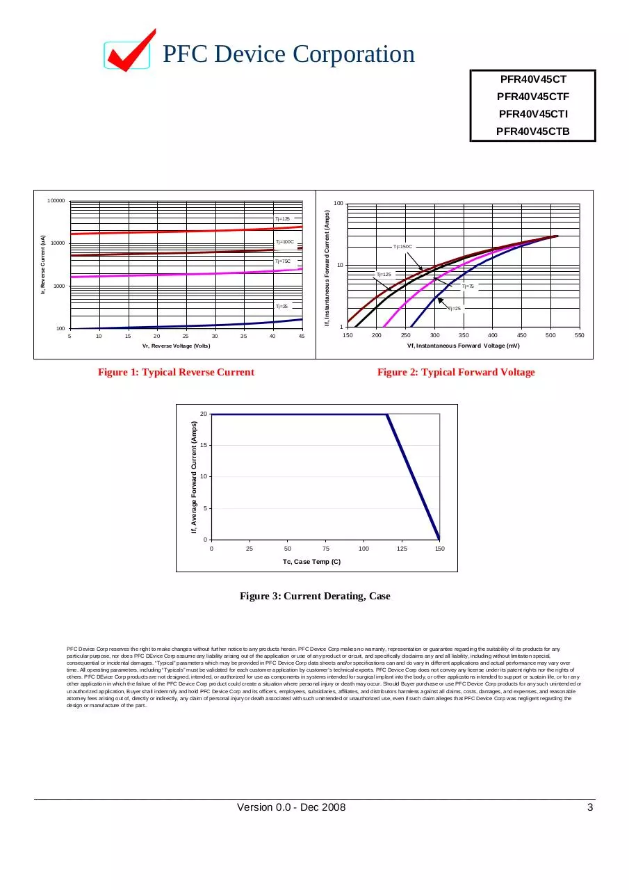
100000
If, Instantaneous Forward Current (Amps)
100
Ir, Reverse Current (uA)
Tj=125
Tj=100C
10000
Tj=75C
1000
Tj=25
100
5
10
15
20
25
30
35
40
45
Tj=150C
10
Tj=125
Tj=75
Tj=25
1
150
200
250
Vr, Reverse Voltage (Volts)
300
350
400
450
500
550
Vf, Instantaneous Forward Voltage (mV)
Figure 1: Typical Reverse Current
Figure 2: Typical Forward Voltage
If, Average Forward Current (Amps)
20
15
10
5
0
0
25
50
75
100
125
150
Tc, Case Temp (C)
Figure 3: Current Derating, Case
PFC Device Corp reserves the right to make changes without further notice to any products herein. PFC Device Corp makes no warranty, representation or guarantee regarding the suitability of its products for any
particular purpose, nor does PFC DEvice Corp assume any liability arising out of the application or use of any product or circuit, and specifically disclaims any and all liability, including without limitation special,
consequential or incidental damages. “Typical” parameters which may be provided in PFC Device Corp data sheets and/or specifications can and do vary in different applications and actual performance may vary over
time. All operating parameters, including “Typicals” must be validated for each customer application by customer’s technical experts. PFC Device Corp does not convey any license under its patent rights nor the rights of
others. PFC DEvice Corp products are not designed, intended, or authorized for use as components in systems intended for surgical implant into the body, or other applications intended to support or sustain life, or for any
other application in which the failure of the PFC Device Corp product could create a situation where personal injury or death may occur. Should Buyer purchase or use PFC Device Corp products for any such unintended or
unauthorized application, Buyer shall indemnify and hold PFC Device Corp and its officers, employees, subsidiaries, affiliates, and distributors harmless against all claims, costs, damages, and expenses, and reasonable
attorney fees arising out of, directly or indirectly, any claim of personal injury or death associated with such unintended or unauthorized use, even if such claim alleges that PFC Device Corp was negligent regarding the
design or manufacture of the part..
________________________________________________________________________________________________
Version 0.0 - Dec 2008
3
Download pfc PFR40V45CT
pfc_PFR40V45CT.pdf (PDF, 92.35 KB)
Download PDF
Share this file on social networks
Link to this page
Permanent link
Use the permanent link to the download page to share your document on Facebook, Twitter, LinkedIn, or directly with a contact by e-Mail, Messenger, Whatsapp, Line..
Short link
Use the short link to share your document on Twitter or by text message (SMS)
HTML Code
Copy the following HTML code to share your document on a Website or Blog
QR Code to this page

This file has been shared publicly by a user of PDF Archive.
Document ID: 0000129939.