eng334 411 (PDF)
File information
Title: I334-411.qxp
Author: dusty
This PDF 1.3 document has been generated by PScript5.dll Version 5.2.2 / GNU Ghostscript 7.06, and has been sent on pdf-archive.com on 27/05/2014 at 21:48, from IP address 124.182.x.x.
The current document download page has been viewed 559 times.
File size: 1.85 MB (3 pages).
Privacy: public file


File preview
2007 Suzuki Bandit 1250
I n s ta l l a t i o n I n s t r u c t i o n s
Parts List
1
Power Commander
1
CD-ROM
1
Button Adjustment Display
USB Cable
1
Installation Guide
1
Power Adapter
1
O2 Eliminator
2
Power Commander Decals
2
Dynojet Decals
2
Velcro
®
1
Strip
Alcohol Swab
1
Faceplate Buttons
Wire tap
Expansion Port
USB Port
The ignition MUST be turned
OFF before installation!
You can also download the Power
Commander software and latest maps
from our web site at:
www.powercommander.com
PLEASE READ ALL DIRECTIONS BEFORE STARTING INSTALLATION
Dynojet Research 2191 Mendenhall Drive North Las Vegas, NV 89081 (800) 992-4993 www.powercommander.com
334-411
www.powercommander.com
2007 Suzuki Bandit 1250 - PCIII USB - 1
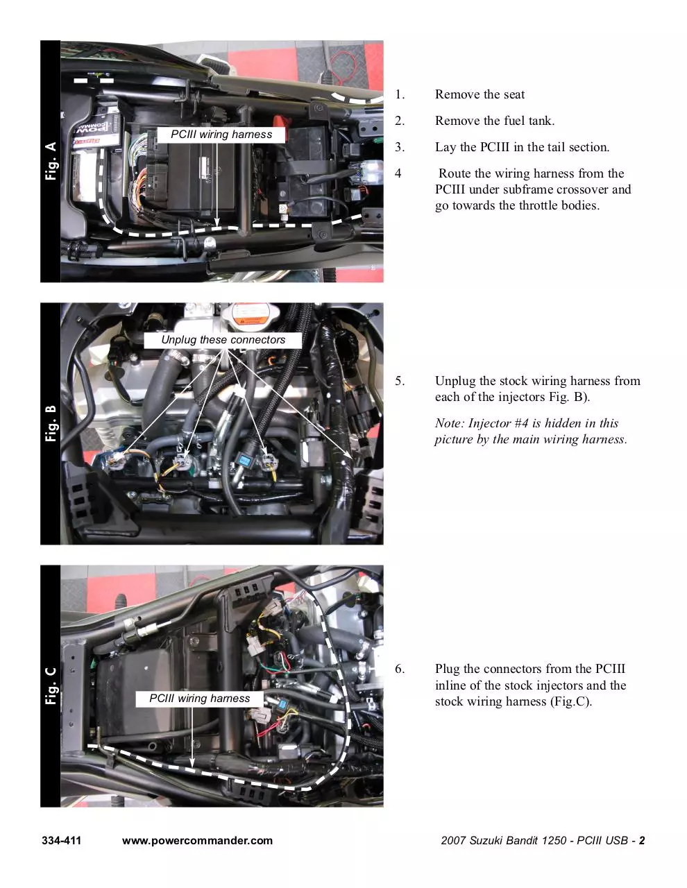
Fig. A
PCIII wiring harness
1.
Remove the seat
2.
Remove the fuel tank.
3.
Lay the PCIII in the tail section.
4
Route the wiring harness from the
PCIII under subframe crossover and
go towards the throttle bodies.
Unplug these connectors
Fig. C
Fig. B
5.
334-411
Unplug the stock wiring harness from
each of the injectors Fig. B).
Note: Injector #4 is hidden in this
picture by the main wiring harness.
6.
PCIII wiring harness
www.powercommander.com
Plug the connectors from the PCIII
inline of the stock injectors and the
stock wiring harness (Fig.C).
2007 Suzuki Bandit 1250 - PCIII USB - 2
7.
Locate the Throttle Position Sensor
which is located on the left hand side
of the throttle bodies. Unplug this
Grey wire from PCIII
connector to gain access to the wires.
Fig. D
9.
Attach the supplied wire tap to the
PINK wire with a BLACK stripe
(Fig.D).
This connection can be done further
up the harness than what is shown in
Fig. D.
10.
Plug the grey wire from the PCIII into
Note:
It is recommended to use dielectric
11.
Plug the TPS connector back onto the
12
Attach the ground wire from the PCIII
the wire tap (Fig.D).
grease on these connections.
throttle body.
Fig. E
Ground wire
PCIII harness
to the negative side of the battery
(Fig. E).
13
Reinstall the fuel tank making sure
the PCIII harness does not get
pinched.
14
Secure the PCIII in the tail section
using the supplied velcro.
Make sure
to clean both surfaces with the alcohol
swab before attaching.
15
Locate the stock O2 sensor under the
left hand side cover.
Unplug the
sensor from stock wiring harness and
connect the Dynojet O2 eliminator.
The stock O2 sensor does not need to
be connected to anything.
334-411
www.powercommander.com
2007 Suzuki Bandit 1250 - PCIII USB - 3
Download eng334-411
eng334-411.pdf (PDF, 1.85 MB)
Download PDF
Share this file on social networks
Link to this page
Permanent link
Use the permanent link to the download page to share your document on Facebook, Twitter, LinkedIn, or directly with a contact by e-Mail, Messenger, Whatsapp, Line..
Short link
Use the short link to share your document on Twitter or by text message (SMS)
HTML Code
Copy the following HTML code to share your document on a Website or Blog
QR Code to this page

This file has been shared publicly by a user of PDF Archive.
Document ID: 0000165483.