GGR (PDF)
File information
This PDF 1.6 document has been generated by Adobe Acrobat Pro 11.0.6, and has been sent on pdf-archive.com on 08/11/2014 at 19:08, from IP address 68.81.x.x.
The current document download page has been viewed 608 times.
File size: 1.08 MB (10 pages).
Privacy: public file


File preview
Sega GameGear
Backlight Replacement Kit
Hand Held Legend presents:
Custom Game Gear Backlight Installation Instruction
Hello classic gamers! Congratulations on your purchase of Hand Held Legend’s custom Game Gear Backlight
Modification. The following instructions are fairly straight-forward and are written to be as in-depth and easy
to follow as possible, but it is assumed that you have some kind of previous knowledge of soldering and basic
electronic device servicing.
Included Items:
1) Custom Game Gear Backlight
2) 100 ohm Resistor
Required Items:
1) Soldering Pen
2) Solder
3) Phillips head screwdriver
4) Security bit screwdriver (only 1 screw is required for this, the same screwdriver can be used on
multiple other applications)
5) Straight saw to cut plastic (used for modeling, can use Dremel if you can cut straight)
6) Side cuts or something to cut wiring
7) Razorblade
Optional Items:
1) Shrink tube Insolation for wires
2) De-soldering braid/tool
3) Electrical tape
4) Needle nose pliers (to pick the screws up off the mainboard, less of a chance to lose them)
5) 3mm LED Light (if you wish to change the existing red LED to another color, do this step when you have
the board removed from the case)
Procedure
First off, make sure you have a well prepared work area to perform this mod. It always helps to have ample
room to work and a solid, clean surface to do any sort of electronics repair. To be extra careful, it doesn’t
hurt to have an anti-static strap to ensure the protection of the delicate electronic components in your
system. Also make sure to set your parts on soft, non-abrasive areas to avoid any possible scratches or dings.
I’ve always had a clean micro-fiber cloth to set my case parts on, but a tissue or soft paper towel is fine.
Flip over the GG so the screen is facing down. Make sure to have a napkin or tissue underneath the screen to
avoid any scratching of the front screen (which a GG is very susceptible to). Remove the battery covers and
the 6 Phillips head screws; refer to Figure (1) for details. The security screw in the cartridge slot is 4.5mm and
is the only security screw in the entire unit. Once you have all the screws removed, remove the rear section of
the case (3 connectors will keep the case from completely separating.
Figure (1)
There were different versions of the GG board, but the principle is pretty much the same. A quick internet
search can help you find specs on your unit’s specific configuration. Next, carefully disconnect the 3
connectors at the top of the system. Don’t pull them by the wires, since you could potentially break them.
Once the connectors are disconnected, the back half of the case can now be removed and set aside.
Now, we can see all the inner workings of the GG. There are 8 screws holding the board in the case. Refer to
red circles in Figure (2) for the locations of the screws and remove them. At this point you have probably
collected a fair number of screws, so hopefully you have them in an area where you can’t lose them. As you
can see from the yellow circles in Figure (2), the reflective cover for the lighting tube is held on by 4 screws.
This cover has to be removed in order to perform this mod.
Figure (2)
Remove the reflective cover to get access to the lighting tube, refer to Figure (3).
Figure (3)
It’s now time to forever remove that power-hungry, battery sucking, monster of a tube. First, you will want to
cut the 2 wires holding the tube to the board. There are also 2 resistors next to the ends of the tube, which
are no longer needed and can be discarded. Figure (4) shows the location of the wires and resistors to cut.
Once the tube and endcaps have been separated from the board, they can be thrown away. This is now the
time to begin removing the extra components, which were part of the tube circuitry.
Figure (4)
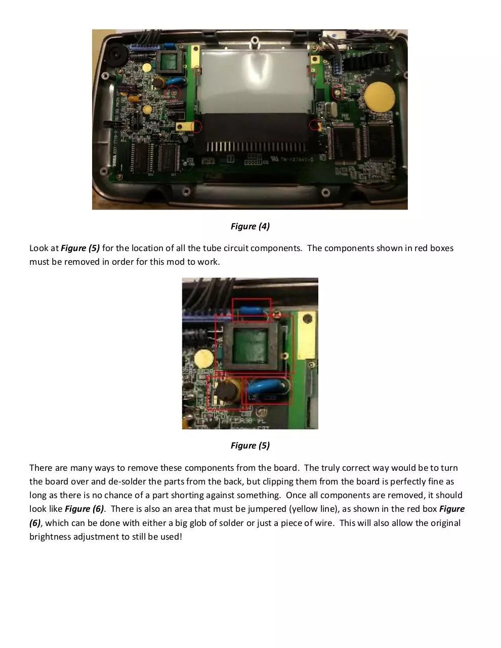
Look at Figure (5) for the location of all the tube circuit components. The components shown in red boxes
must be removed in order for this mod to work.
Figure (5)
There are many ways to remove these components from the board. The truly correct way would be to turn
the board over and de-solder the parts from the back, but clipping them from the board is perfectly fine as
long as there is no chance of a part shorting against something. Once all components are removed, it should
look like Figure (6). There is also an area that must be jumpered (yellow line), as shown in the red box Figure
(6), which can be done with either a big glob of solder or just a piece of wire. This will also allow the original
brightness adjustment to still be used!
Figure (6)
Now its time to prepare the unit for the backlight install. Figure (7) shows the LCD and the diffuser together.
Figure (7)
You will need to remove the white light diffuser from the back of the LCD screen. This can be accomplished by
using an x-acto knife or razor blade and CAREFULLY slide it into the middle of the 2 pieces, as shown in Figure
(8). Make sure you insert the razor on the same side as shown in the picture (the side with the most glue).
Gently slide the razor up and down the glued area until the white diffuser separates from the LCD screen. Be
very gentle with this step, the LCD screen is glass and can be easily broken.
Figure (8)
This white diffuser has to be cut in order for the backlight to fit. Take your straight saw and cut along the
edges of the white diffuser as it shows with red lines in Figure (9). The center part of the diffuser can be
tossed, but the 2 outside pieces need to be kept to be able to reattach the reflector cover.
Figure (9)
Its time to begin reassembling the board and the LCD screen. Place the LCD screen back in its original position
under the board. Take the 2 pieces of white diffuser cut from Figure (9) and place them back in their original
location between the board and the LCD, as shown in Figure (10). They should somewhat grab the sides of
the LCD screen as they did when they were whole. Line up the holes in the board with the holes in the pieces
as best as you can, again refer to Figure (10). It is important to make sure the holes are lined up with the
same placement as the reflective cover, since the reflective cover will be re-assembled to those holes later on.
Figure (10)
Finally, its time to install the backlight! Take the backlight and place it into the space where the white diffuser
used to be. Make sure you keep the wires at the top of the unit and that the backlight itself is facing the right
way (the opaque part is face down towards the screen and the white part is up facing you). See Figure (11) for
details.
Figure (11)
The backlight will have to be powered using the original circuit for the light tube. Make sure you attach the
100 ohm resistor to the positive (RED) wire of the backlight. The resistor is important to decrease the 5V
coming from the board to about 3V, so the backlight LEDs don’t burn out. Solder the negative (BLACK) wire to
the location shown in Figure (12) and solder the red wire with the attached resistor to the other location in
Figure (12). It might be a bit hard to see, but the positive wire is connected to the middle hole of the 5 holes
at the top of the white square. I am usually a bit overprotective when it comes to protection against shorting,
so after I soldered the resistor onto the backlight’s positive wire I added a shrink wrap sleeve to the area
before I soldered it onto the board. I recommend this step, but its not 100% necessary. I also place 2 small
pieces of electrical tape on top of the exposed solder on the negative wire and the jumper, as another
precaution against shorting.
Figure (12)
Its finally time to reassemble everything. It’s basically the initial disassembly process, but in reverse order.
Place the reflective cover back to its original location, paying attention to the 4 holes in the board and how
they line-up with the modified diffuser cutoffs. Figure (13) shows how the reflective cover fits back into its
original location.
Download GGR
GGR.pdf (PDF, 1.08 MB)
Download PDF
Share this file on social networks
Link to this page
Permanent link
Use the permanent link to the download page to share your document on Facebook, Twitter, LinkedIn, or directly with a contact by e-Mail, Messenger, Whatsapp, Line..
Short link
Use the short link to share your document on Twitter or by text message (SMS)
HTML Code
Copy the following HTML code to share your document on a Website or Blog
QR Code to this page

This file has been shared publicly by a user of PDF Archive.
Document ID: 0000193122.