CT 2080 Series User Manual Jammers4u www.jammers4u.com (PDF)
File information
Title: ck-101b
Author: LEE221
This PDF 1.5 document has been generated by Microsoft® Word 2010, and has been sent on pdf-archive.com on 24/01/2015 at 12:49, from IP address 91.185.x.x.
The current document download page has been viewed 626 times.
File size: 581.98 KB (4 pages).
Privacy: public file


File preview
JAMMER USER’S MANUAL
- 1 -
Version 1.1
JAMMER USER’S MANUAL
Version 1.1
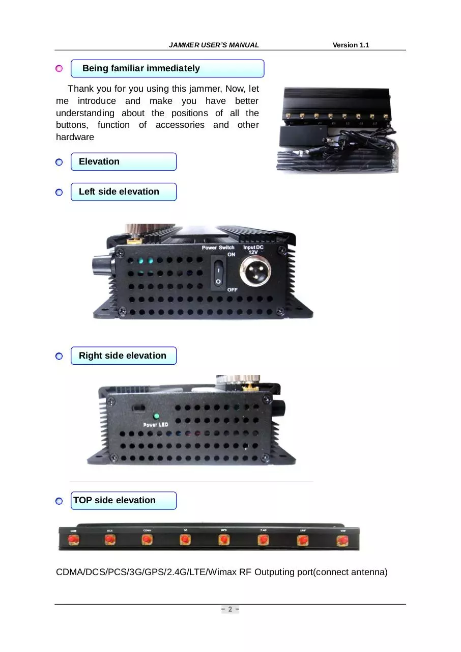
Being familiar immediately
Thank you for you using this jammer, Now, let
me introduce and make you have better
understanding about the positions of all the
buttons, function of accessories and other
hardware
Elevation
Left side elevation
Right side elevation
TOP side elevation
CDMA/DCS/PCS/3G/GPS/2.4G/LTE/Wimax RF Outputing port(connect antenna)
- 2 -
JAMMER USER’S MANUAL
Version 1.1
Technology index
Output port
Frequency
Average outputting power
Channel outputting power
CDMA
851-894MHz
35dBm
5dBm/30KHz(min)
DCS&PCS
1805-1990MHz
33dBm
2dBm/30KHz(min)
GSM
925-960MHz
33dBm
2dBm/30KHz(min)
3G
2110-2170MHz
33dBm
2dBm/30KHz(min)
WIFI2.4G
2400-2500MHz
30dBm
0dBm/30KHz(min)
GPS
1570-1580MHz
31dBm
5dBm/30KHz(min)
4GLTE
700-800MHz
34dBm
5dBm/30KHz(min)
4GWIMAX
2496-2690MHz
30dBm
3dBm/30KHz(min)
Power supply: AC adapter (AC220V-DC12V)
Shielding Radius: (2-40) meters@-75dBm still depends on the strength signal in
given area.
Dimension: (width, height, length) 140x51x355mm
Starting use
Carefully open up the packaging case and reserve it for the purpose of
loading or shipping in the future.
Please check whether all the things are kept in good condition or not. If you
encounter the bad condition of the elements or being damaged, please contact
your dealer immediately.
Connecting system
After connecting all of the
subassemblies, please connect one
side (DC) of power supply wire onto
the device's power port, and connect
the other side to the power supply jack.
Turning on your jammer
After connecting all of the surrounding elements and tie wires, please press the
switch of left side to ON then the jammer will be working normally. The power pilot
lamp will be green
- 3 -
JAMMER USER’S MANUAL
Version 1.1
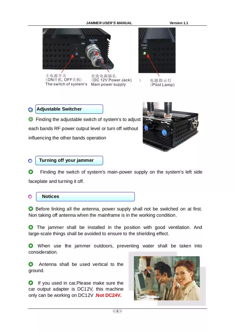
◎ Adjustable Switcher
◎ Finding the adjustable switch of system's to adjust
each bands RF power output level or turn off without
influencing the other bands operation
Turning off your jammer
◎
Finding the switch of system's main-power supply on the system's left side
faceplate and turning it off.
Notices
◎ Before linking all the antenna, power supply shall not be switched on at first.
Non taking off antenna when the mainframe is in the working condition.
◎ The jammer shall be installed in the position with good ventilation. And
large-scale things shall be avoided to ensure to the shielding effect.
◎ When use the jammer outdoors, preventing water shall be taken into
consideration.
◎ Antenna shall be used vertical to the
ground.
◎ If you used in car,Please make sure the
car output adapter is DC12V, this machine
only can be working on DC12V .Not DC24V.
- 4 -
Download CT-2080 Series User Manual Jammers4u www.jammers4u.com
CT-2080 Series User Manual Jammers4u www.jammers4u.com.pdf (PDF, 581.98 KB)
Download PDF
Share this file on social networks
Link to this page
Permanent link
Use the permanent link to the download page to share your document on Facebook, Twitter, LinkedIn, or directly with a contact by e-Mail, Messenger, Whatsapp, Line..
Short link
Use the short link to share your document on Twitter or by text message (SMS)
HTML Code
Copy the following HTML code to share your document on a Website or Blog
QR Code to this page

This file has been shared publicly by a user of PDF Archive.
Document ID: 0000205579.