Directional ralys (PDF)
File information
Author: Ahmadullah
This PDF 1.6 document has been generated by PScript5.dll Version 5.2.2 / Bullzip PDF Printer / www.bullzip.com / Freeware Edition (not registered), and has been sent on pdf-archive.com on 25/03/2015 at 23:01, from IP address 168.235.x.x.
The current document download page has been viewed 4465 times.
File size: 166.53 KB (8 pages).
Privacy: public file


File preview
Directional Relay
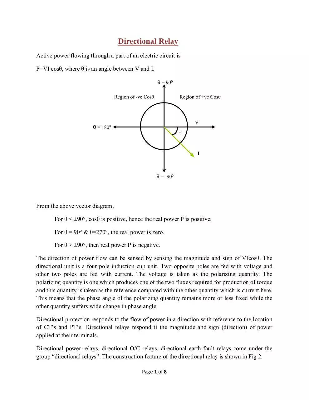
Active power flowing through a part of an electric circuit is
P=VI cosθ, where θ is an angle between V and I.
From the above vector diagram,
For θ < ±90°, cosθ is positive, hence the real power P is positive.
For θ = 90° & θ=270°, the real power is zero.
For θ > ±90°, then real power P is negative.
The direction of power flow can be sensed by sensing the magnitude and sign of VIcosθ. The
directional unit is a four pole induction cup unit. Two opposite poles are fed with voltage and
other two poles are fed with current. The voltage is taken as the polarizing quantity. The
polarizing quantity is one which produces one of the two fluxes required for production of torque
and this quantity is taken as the reference compared with the other quantity which is current here.
This means that the phase angle of the polarizing quantity remains more or less fixed while the
other quantity suffers wide change in phase angle.
Directional protection responds to the flow of power in a direction with reference to the location
of CT’s and PT’s. Directional relays respond ti the magnitude and sign (direction) of power
applied at their terminals.
Directional power relays, directional O/C relays, directional earth fault relays come under the
group “directional relays”. The construction feature of the directional relay is shown in Fig 2.
Page 1 of 8
CT
Disc
CT
PT
The torque of the induction relay is proportional to the product of two fluxes and sine of the
angle between them i.e. T α φ1φ2 sinθ. Maximum torque will occur when θ=90°.
The phasor diagram of the directional relay is shown below in Fig 3.
浘Ǝ
Here
is the flux due to the voltage coil and lags behind the voltage by about almost 60° to 70°
(α). And is the flux due to the current coil. The net torque is produced due to the interaction of
and . the torque is maximum when the two fluxes are displaced by 90°. Here the dotted line
in the phasor diagram represents the desired position of for maximum torque. Since is the
reference or polarizing quantity and
has fixed position with respect to for a particular
design, the angle between the dotted line and the polarizing quantity
is known as the
maximum torque angle and is normally denoted by τ, maximum torque is produced. By changing
the internal angle α of the relay, the characteristic of the directional relay could be varied.
Page 2 of 8
The torque developed by a directional unit is given byT=
Where,
Sin (α-θ)-K……. (1)
is the voltage applied to the voltage coil.
is the current in the voltage coil
is the current in the current coil
is the flux due to
is the flux due to
θ is the angle between
and
K is the restraining force including spring and friction.
The sign of the torque depends upon the sign of Sin (α-θ). Sin (α-θ) is positive when the angle
(α-θ) lies between 0-180° and negative when lies between 180°-360°. For a particular installation
Sin (α-θ) is constant, K1 then torque-
畘Ǝ
− …….. 2
T=
Under threshold condition,
T= 0 = VI - K
Or, VI=K/ =constant……… (3)
The equation can be represented by a
rectangular hyperbola shown in Fig 4.
V
Vmin
Imin
I
For the operation of the relay, the product of V and I should give a minimum torque which
exceeds the friction and spring torque. From the characteristic it is clear that it is not enough to
have the product greater than K, but there is minimum value of voltage and a minimum value of
current required for the torque to be developed. For a close up fault the voltage at the relay point
may collapse, so under that condition the relay will not operate. The maximum distance up to
which the voltage is less than the minimum voltage required is known as the dead zone of the
directional relay.
For satisfactory results the directional element in each relay must respond quickly and
decisively; in a forward direction when the operation of the over current element is required and
in reverse direction, to restrain, when it is not. To achieve this for all types of faults the relay
Page 3 of 8
cannot be connected to operate on true wattmeter type since the torque would not be sufficient
when the voltage is small as occurs, for example, with close up faults. To overcome this, and
thus to ensure that sufficient torque is always available; each relay is supplied with current from
its respective phase and voltage from two phases.
One of the two methods of connection is normally used.
1. 30° connection.
2. 90° connection
The first type employs a relay with a unity power factor characteristic i.e. where maximum
torque occurs with the applied current and voltage in phase. The phase A relay is supplied with A
phase current and A-C voltage, the B phase relay with B phase current and B-A voltage, and the
C phase relay with C phase current and C-B voltage.
畘Ǝ
30° connection and its vector diagram are shown in Fig. 5. Since the relay is uncompensated for
phase angle the maximum torque will occur when the primary power factor is cos300 = 0.866
leading.
The second type of connection (90° connection) gives a better performance with high torque.
This requires a relay which has internal compensation so that maximum torque occurs when the
Page 4 of 8
relay current leads the voltage by 45°. For 90° connection the A phase current is combined with
the B-C voltage in the A phase relay. In the B phase, the B phase current and A-C voltage are
applied; and in the C phase, the C phase current and B-A voltage are applied. The connection
and the vector diagram are shown in Figure.
畘Ǝ
With these connection whatever the type of fault i.e. line to ground, line to line double line to
ground or three phase faults, the phase angle between the current and voltage will always be well
below 90°. The connection configuration of current coil and voltage coil for relays in 3 phases
for both 30° and 90° connection are shown in the following table:
30° connection
90° connection
Relay
I
Relay
I
II
II
III
III
Page 5 of 8
Problem: A circuit with an impedance angle of 10° is to be protected by directional O/C relays.
Use 30° connection for the directional element. The relay potential coil has an impedance of
1000∠60°Ω. What modification should be made and also find the quantitative value if it is
desired that the relay will develop maximum torque under a close up fault condition on phase ‘a’.
The angle between
and
at relay location becomes 50° under above mentioned fault
condition.
Solution:
For the cable, the impedance angle under operating condition is 10°. With 30° connection the
and
is 30°.
Lags
by 30° and therefore leads
by 20°. The
phase angle between
relay quantitates are current proportional to and voltage proportional to
for a fault on phase
‘a’. In case of fault on phase ‘a’ the voltages of this phase up to the relay point becomes quiet
small and say the phase angle between and
becomes 50° instead of 30°, thereby the angle
becomes 40°. The phasor diagram is shown in the figure:
between and
畘Ǝ
Voltage
is applied to the potential coil which has an impedance angle of 60° and the position
of the current ! is shown in the phasor diagram. The torque to be maximum, the angle between
and should be 90°; therefore a capacitor of suitable value should be connected such that the
impedance angle becomes 50° rather than 60° as shown by a dotted phasor in the phasor
diagram.
1000∠60°= (500+j866)
For angle to be 50°, tan-1(X/R) = 50
Or, tan 50= X/R.
Or, X= 596,
but we have inductive reactance of 866 Ω
Therefore, capacitive reactance required
= 866-596= 270Ω
" = 1/(2πfC), or C = 1/(315*270) = 11.8 µf
Page 6 of 8
Protection of ring mains by directional over current relay
Directional relays are more commonly applied to ring mains. The co-ordination of directional
O/C relays for the protection of a ring main are shown and explained here.
畘Ǝ
Page 7 of 8
As shown in Fig. 1(a), four substations are interconnected and fed through one source. The relays
A1 and B1 at the supply end are non-directional relays and the rest are directional relays. The
usual procedure for grading the relays in an interconnected system is to open the ring at the
supply point A1 and considering the system as a radial feeder connected to one source as shown
in Fig. 1(b). The relays (directional) are arranged to operate in the sequence A2 in 0.1 sec, A3 in
0.5 sec and A4 in 0.9 sec and B1 (Non-directional) in 1.3 sec.
Next open the ring at B1 and the directional relay grading are performed in the sequence B2 in
0.1 sec, B3 in 0.5 sec, B4 in 0.9 sec and the non-directional relay A1 in 1.3 sec as shown in Fig.
1(b). Total protection scheme is shown in Fig. 1(d).
Consider a fault as shown in fig. 1(d), the fault will be as shown by the dotted line with arrow.
The relays A1, B4, B3, and B1 and A4 will start moving. The relays B3 will operate first as this has
minimum operating time out of these relays; therefore after a time 0.5 sec the relays B4 and A1
will reset as the fault current ceases to flow through these relays. In another fault path, A4 will
operate earlier than B1 as the operating time of the former is less than that of the latter. Hence the
faulty feeder between the relays B3 and A4 is isolated from the source. Discrimination of the
faulty feeder is carried out according to time and fault current direction.
When two or more power sources feed into the ring main, time graded O/C protection is difficult
to apply and full discrimination may not be possible.
畘Ǝ
Page 8 of 8
Download Directional ralys
Directional ralys.pdf (PDF, 166.53 KB)
Download PDF
Share this file on social networks
Link to this page
Permanent link
Use the permanent link to the download page to share your document on Facebook, Twitter, LinkedIn, or directly with a contact by e-Mail, Messenger, Whatsapp, Line..
Short link
Use the short link to share your document on Twitter or by text message (SMS)
HTML Code
Copy the following HTML code to share your document on a Website or Blog
QR Code to this page

This file has been shared publicly by a user of PDF Archive.
Document ID: 0000217270.