Generator Protection (PDF)
File information
Author: User
This PDF 1.6 document has been generated by PScript5.dll Version 5.2.2 / Bullzip PDF Printer / www.bullzip.com / Freeware Edition (not registered), and has been sent on pdf-archive.com on 25/03/2015 at 23:01, from IP address 168.235.x.x.
The current document download page has been viewed 4029 times.
File size: 254.23 KB (10 pages).
Privacy: public file


File preview
Generator Protection
A modern generating unit is a complex system comprising the generator stator winding and
associated transformer and unit transformer, the rotor with its field winding and exciters, and the
turbine and its associated condenser and boiler complete with auxiliary fans and pumps. Faults of
many kinds can occur within this system for which diverse protective means are needed. The
amount of protection applied will be governed by economic considerations, taking into account
the value of the machine and its importance to the power system as a whole.
The following types of faults may occur in generator:
1. Stator faulta. Phase to ground fault- Very common
b. Phase to phase fault- Less common, and eventually this fault will involve
earth very soon.
c. Inter turn fault- Uncommon, not covered by conventional protection system.
This fault will eventually give rise to earth fault and cleared by E/F protection.
2. Rotor fault
3. Abnormal running conditiona. Loss of excitation
b. Unbalanced loading
c. Overloading
d. Failure of prime mover
e. Over speeding
f. Over voltage
Page 1 of 10
4. Other problems requiring attentiona. Low vacuum
b. Lubrication oil failure
c. Excessive vibration
d. Difference in expansion between rotating and stationary parts.
e. Bearing temperature
f. Stator winding temperature
g. Loss of boiler firing
Some of the above mentioned problems sound an alarm and some cause tripping.
Small and medium sized sets may be directly connected to the distribution system. A large unit is
usually associated with an individual transformer, through which the set is coupled to the EHV
primary transmission system. No switchgear is provided between the generator and the
transformer, which are treated as a unit; a unit transformer may be tapped off from the
interconnection for the supply of power to auxiliary plant.
Main transformer
G
Auxiliary
transformer
HV bus
bar
Auxiliary
supply
Generator transformer
unit
Earthing of a generator
The neutral point of a generator is usually earthed so as to facilitate protection of the stator
winding and associated system. Impedance is inserted in the earthing lead to limit the magnitude
of earth fault current. Severe arcing to the machine core burns the iron at the point of fault and
welds lamination together. Replacement of a faulty conductor may not be serious matter but
damage to the core cannot be ignored. Degree of fault current limitation varies from
approximately rated current on one and to comparatively low value on the other. Some
manufacturers have found that if the earth fault current does not exceed 5A, burning of core will
not readily occur.
Page 2 of 10
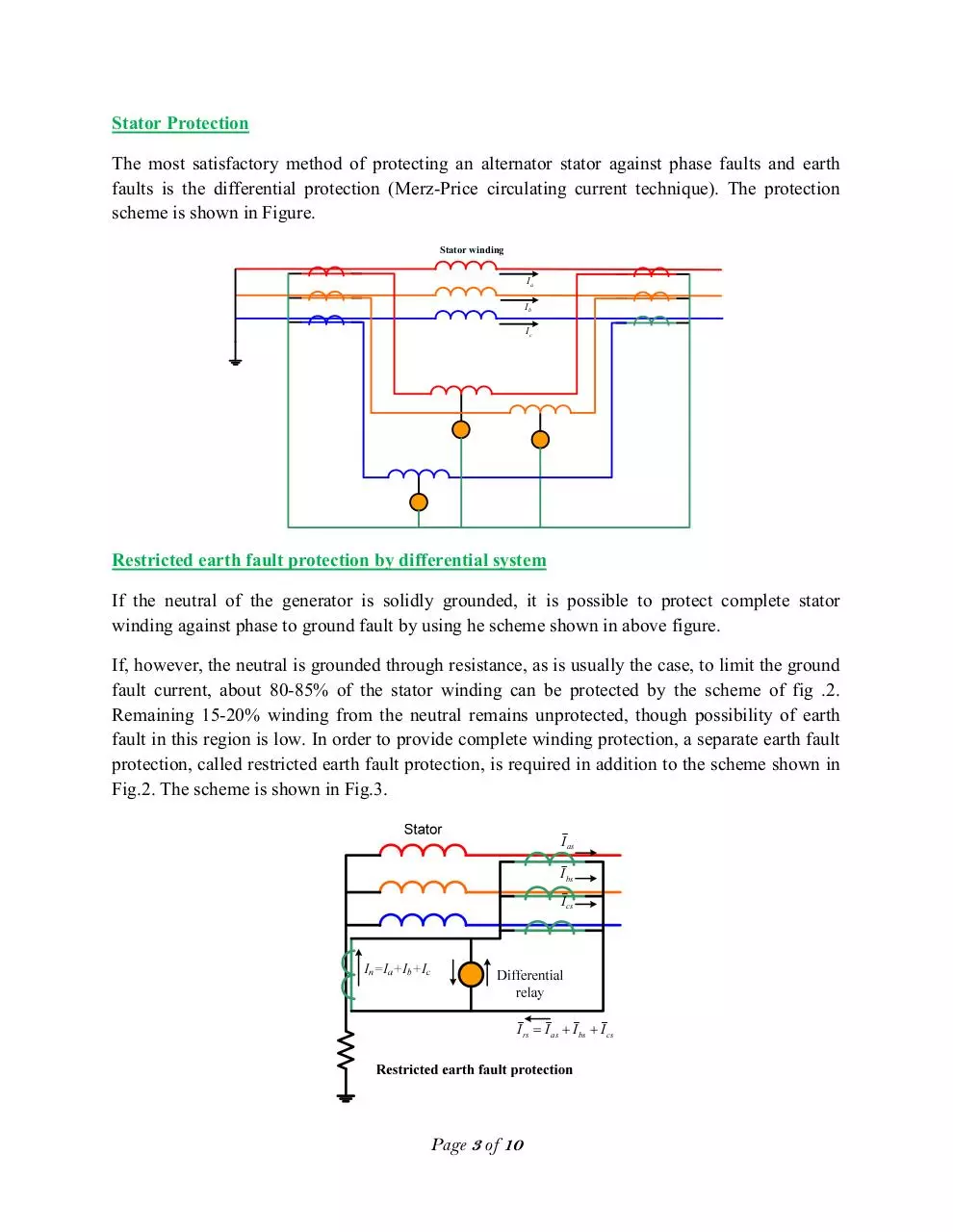
Stator Protection
The most satisfactory method of protecting an alternator stator against phase faults and earth
faults is the differential protection (Merz-Price circulating current technique). The protection
scheme is shown in Figure.
Stator winding
Ia
Ib
Ic
Restricted earth fault protection by differential system
If the neutral of the generator is solidly grounded, it is possible to protect complete stator
winding against phase to ground fault by using he scheme shown in above figure.
If, however, the neutral is grounded through resistance, as is usually the case, to limit the ground
fault current, about 80-85% of the stator winding can be protected by the scheme of fig .2.
Remaining 15-20% winding from the neutral remains unprotected, though possibility of earth
fault in this region is low. In order to provide complete winding protection, a separate earth fault
protection, called restricted earth fault protection, is required in addition to the scheme shown in
Fig.2. The scheme is shown in Fig.3.
I as
I bs
I cs
I rs = I as + I bs + I cs
Page 3 of 10
Over current and earth fault protection
It is usual to apply over current relays of IDMT pattern to generators as a generator back up
feature. If a single generator feeds an isolated system, over current protection scheme for
winding fault will be used as shown in figure:
If a generator operates in parallel with others and forms a part of an extensive interconnected
system, then over current and earth fault relays at the line end of the machine, as shown in
following figure, will provide the backup protection of any fault on the stator winding of the
machine under consideration. In this case the operation of the backup scheme for stator winding
fault is due to current fed back from the system.
Stator earth protection
Stator winding protection can usefully be supplemented by an earth fault system in addition to
the over current relay. An earth fault relay is energized by a CT in the neutral circuit. For a
machine directly connected to a bus bar, this earth fault relay must be graded with feeder
protection. For a generator transformer unit, the stator winding and the primary winding of the
transformer form an isolated system which cannot interchange the zero sequence current with the
transmission system; for this reason no grading problem exists.Two alternative methods are
employed for the above mentioned earth fault protection shown in Fig .6(a) and 6(b).
Page 4 of 10
First method
For the large generator if the neutral is earthed
through high resistance, then the scheme shown
in Fig. 6(a) is employed. Here EF1 is an
instantaneous O/C relay with a setting of 10%
(earth fault current is 10% of the full load
current). EF2 is a time delayed IDMT O/C relay
with a setting of as low as 5%. The EF1 can
protect about 90% of the stator winding. EF2
can protect about 95%.
Second method
In this case the neutral of the generator is
connected through a VT, as shown Fig. 6(b).
The rates primary voltage of the VT is
generally equal to phase to neutral voltage of
the generator. The over voltage (E/F) relay is
connected to the secondary of the VT with a
setting of 10% of the rated voltage of the VT.
Loading
resistor
Over voltage
E/F relay
Figure 6(b)
Unbalance loading protection
When a three phase rotating electric machine, including an alternator, is connected to perfectly
balance three phase power system, no negative sequence current is developed in its rotor
winding. If, however the power system is unbalanced as usually is the case, a negative sequence
current of double the system frequency is induced in the rotor winding. This neutrally causes
more rotors over heating than that in the absence of this current. Flow of large amount of
negative sequence current in the rotor winding for long period can cause damage to the rotor
winding. Under this situation a necessary measure must be taken to save the machine. So, the
negative phase sequence current can be used as a parameter in the design of negative sequence
protection scheme of large and expensive rotating electric machines including generators.
Page 5 of 10
Negative Phase Sequence scheme
The twin windings of the two auxiliary CTs ( and ) are so connected to the line CTs that
under normal balanced load condition, , , flow in the direction shown. Impedance
and
are connected across the and . Load impedance is connected across the terminal XX.
When primary load current flows, the current through will be ( − ) and that through will
be ( − ). For a given value of load impedance
and
are chosen such that points P and R
remain at the same potential i.e. Voltages across QR and QP are equal and opposite. Under
unbalance conditions, these voltage differ and an output voltage, proportional to the negative
phase sequence, is produced across XX (voltage E) so as to operate the relay. The protection
remains stable on symmetrical overloads up to about three times the full load current.
Page 6 of 10
Effect of neutral grounding resistance on the detection of earth fault on stator winding of a
generator:
I=
V
R
V
%of winding unprotected
R
Assume R is the resistance in neutral connection to the earth and the fault current for line to
ground fault is equal to full load current of the generator or transformer; the value of impedance
to be inserted in neutral to earth connection is given by: R= ,
Where,
R= impedance in ohms between neutral and ground
V= line to neutral voltage
I= full load current of the largest machine
Percentage of winding unprotected =
. .
ℎ
R= Ohomic value of impedance
= minimum operating current in CT primary
V= line to neutral voltage
Page 7 of 10
Example-1:
A generator is provided with restricted earth fault protection. The ratings of the generator are
11KV, 5000 KVA. The percentage of winding protected against line to ground fault is 80%. The
relay setting is such that it trips for 25% out of balance. Calculate the resistance to be added in
neutral to ground connection.
Solution:
V=11000/√3=6340V
I=5000/ (√3 11)=262A
= 262 ×
So
!
= 65.5 #
The percentage of winding unprotected =
20 =
×%!.!×
%&'
× $×
, or R=1.94 ohms
Example-2
The neutral point of a 10kV alternator is earthed through a resistance of 10 ohms; the relay is set
to operate when there is an out of balance current of 1A. The CTs have a ratio of 1000/5. What
percentage of the winding is protected against fault to earth and what must be the minimum
value of earthing resistance to give 90% protection to each phase winding.
Solution:
1st part:
Out of balance current in pilot wire is 1A.
Corresponding current in CT primary=1x1000/5=200A.
Hence, current
for which the relay operates is 200A.
Therefore, % of winding unprotected =
× $×
=
×
($
×
√)
×
)
=34.64%
So percentage of winding protected = (100-34.64)% = 65.36%
2nd part:
90% of the winding is protected i.e. 10% remains unprotected; R=?
Page 8 of 10
10 =
×
×
($
×
√)
)
=
×
×
×√&
*
+ , R=
×
×
*
×√&
= 2.89+ℎ./
Example-3:
The figure shows a percentage differential relay applied to the protection of an alternator
winding. The relay has a 10% slope of characteristic 0 Vs ( 1 )/2. A high resistance ground
fault occurred near the grounded neutral end of the generator winding while generator is carrying
load. As a consequence, the currents in ampere flowing at each of the winding are shown in the
figure. Will the relay operate to trip the breaker? Assume CT ratio of 400/5.
304+j0
CT1
320+j0
CT2
I1-I2
400/5
400/5
I1
I2
Operation
Pilot wire
10% slope
0.39
No operation
Differential Relay
I1-I2 ≠ 0
3.9
I1 + I 2
2
Solution:
Secondary current of 2 ,
=304×5/400=3.8A
Secondary current of 2 ,
=320×5/400=4.0A
The differential current flowing through the relay coil ǀ∆Iǀ= 3.8-4.0=0.2A
Current in the biasing coil (
1
)/2ǀ= (3.8+4.0)/2=3.9A
From the characteristic curve, it is seen that in order to operate the relay, ǀ
the relay will not operate.
Example-4
The figure shows a differential protection
scheme. The fault current for an earth fault on
the winding are indicated. The CT ratio is
400/5. The relay is set operate for current of
0.1A in its coil. Under the indicated conditions,
will the relay operate? The relay is without
bias.
Page 9 of 10
0
ǀ is 0.2A. Hence
Download Generator Protection
Generator Protection.pdf (PDF, 254.23 KB)
Download PDF
Share this file on social networks
Link to this page
Permanent link
Use the permanent link to the download page to share your document on Facebook, Twitter, LinkedIn, or directly with a contact by e-Mail, Messenger, Whatsapp, Line..
Short link
Use the short link to share your document on Twitter or by text message (SMS)
HTML Code
Copy the following HTML code to share your document on a Website or Blog
QR Code to this page

This file has been shared publicly by a user of PDF Archive.
Document ID: 0000217271.