MA1 build guide vers 0.1.2 (PDF)
File information
Author: Keith Cantwell
This PDF 1.5 document has been generated by Microsoft® Word 2010, and has been sent on pdf-archive.com on 28/03/2015 at 00:45, from IP address 98.227.x.x.
The current document download page has been viewed 856 times.
File size: 3.95 MB (15 pages).
Privacy: public file


File preview
Step 1: Diodes
Locate the two tape strips of diodes that came
with your kit.
When placing diodes, the band
on the diode goes towards the
band on the PCB.
Save the trimmed leads from D5
and D6. These are useful later.
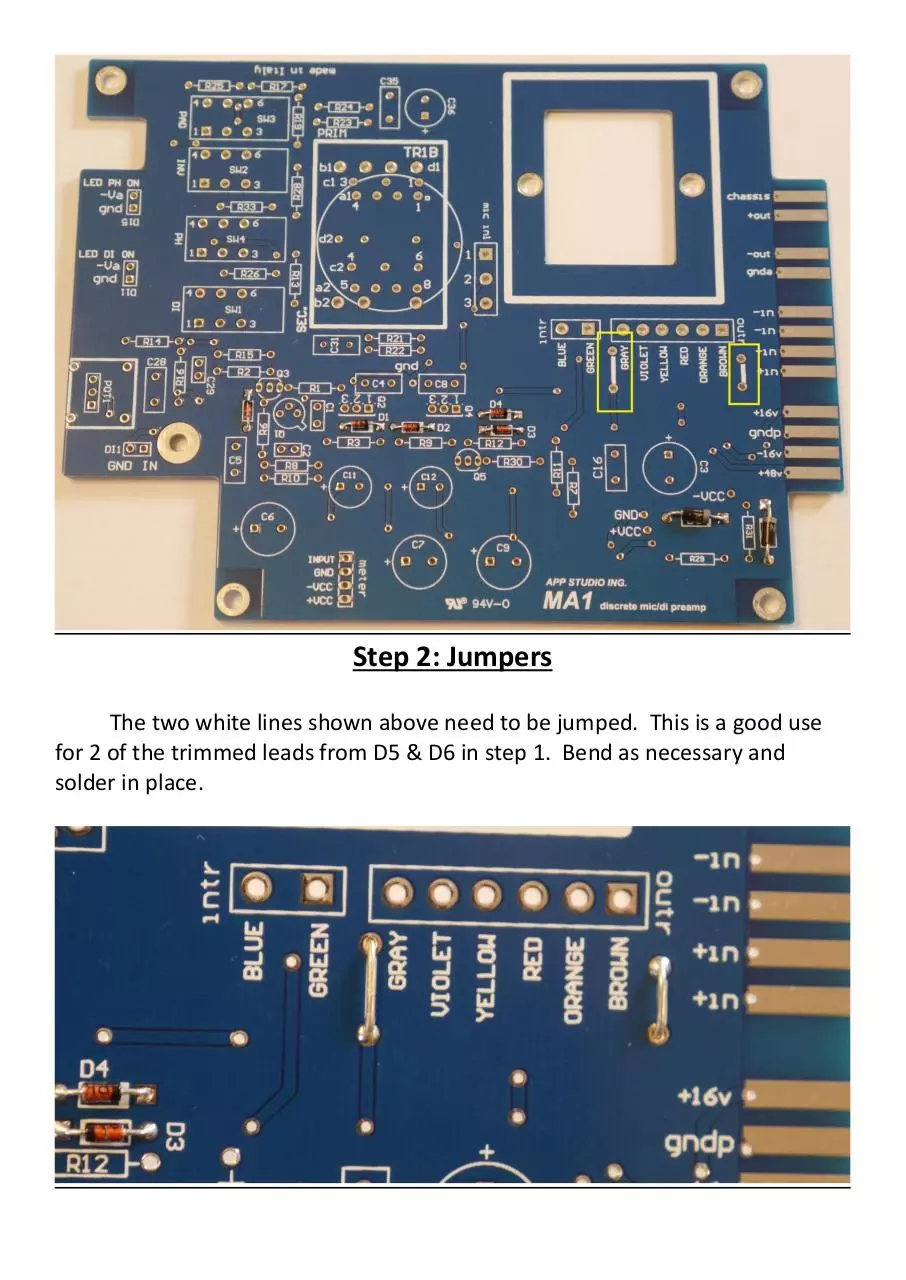
Step 2: Jumpers
The two white lines shown above need to be jumped. This is a good use
for 2 of the trimmed leads from D5 & D6 in step 1. Bend as necessary and
solder in place.
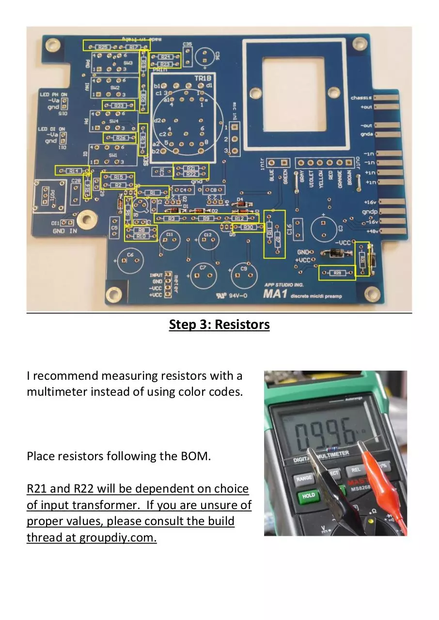
Step 3: Resistors
I recommend measuring resistors with a
multimeter instead of using color codes.
Place resistors following the BOM.
R21 and R22 will be dependent on choice
of input transformer. If you are unsure of
proper values, please consult the build
thread at groupdiy.com.
Step 4: Ceramic and Film caps, Q3 & Q5
Populate capacitors in height order. You will be populating all nonelectrolytic caps except for C28. Leave this capacitor out for now as we
will need access to the rear brackets of the gain pot.
Ceramic: C1, C2, C29
Film: C4, C8, C35; C5, C16
C31 will be dependent on choice of input transformer. If you are
unsure of proper values, please consult the build thread at
groupdiy.com.
Populate Q3 and Q5, BC550C, shown in green above. Proper
orientation follows shape on pcb.
Step 5: Switches
If using the recommended switches and
switch caps from Classic API, then
ensure that the switch cap locks in to
the outermost notch.
Correct switch cap
alignment.
Align switches on PCB
with bottom tabs flush
and solder one pin of each
switch. Check alignment,
and adjust as needed.
Step 6: Front Panel and L-Bracket
Locate the front panel, L bracket, and
hardware that came with your kit.
Find the 2 short
screws and 2 nuts.
Attach the front panel to the L bracket
finger tight.
Attach 4 of the
full length screws
and 4 standoffs
to the L bracket
as shown above.
The 2 nearest the
front panel
should be screwed until flush with the standoff.
Step 7: Gain Pot and LED’s
Insert the gain pot as shown
above so that it is sitting flush
with the PCB.
Gently insert the PCB into the
prepped L bracket and face plate,
guiding the gain pot and switches
into their proper holes. Insert
until you can fit the rear mounting
holes on the PCB over the rear
screws and standoffs on the L
bracket. Once in place, thread the
front L bracket screws into PCB
mounting holes.
Thread the bushing nut
onto the gain pot and
align with the front
panel.
Finger tighten the bushing
nut on the gain pot once
you are happy with
alignment.
Solder the rear pins of
the gain pot bracket to
the pcb.
Using a pair of needlenose pliers,
insert the provided LEDs into the
proper holes on the face plate. The
long leg of the LED will go towards
the bottom of the preamp to the pad
labeled “gnd”, the short leg will go to
the pad labelled “Va”. Use the pliers
to mark where you need to bend the
LEDs.
When you are satisfied with overall alignment, gently remove the PCB
from the L bracket and solder remaining connections for switches, gain
pot, and LEDs.
Step 8: C28; Q2 & Q4; Q1
With the gain pot in place, you can now solder C28.
Locate Q2 = MJE243
and Q4 = MJE253
For correct
orientation, the labelled side goes
towards the input transformer, the
blank side towards the bottom.
Locate the ac126 transistor. There is a small
notch that aligns with the printing on the pcb.
Align pins accordingly, and solder in place.
Step 9: Electrolytic Capacitors
Populate electrolytic
capacitors following the
BOM.
Ensure proper polarity.
The long leg (+) goes
towards the square pads
marked +, the side with
the colored band labelled
(-) goes to the round pad.
Step 10: Input Transformer
The MA1 has footprints for several transformers,
the below shows the EA2622 from Classic API.
Use a thin piece of cardboard, some folded
paper, etc… to block the metal case of the
transformer from the various pads below.
Position the transformer observing
correct pin 1 orientation, then solder
in place.
Step 11: DI Leads
This is a good use for the other 2 cut off leads saved from D5 & D6.
Solder the leads to the DI1 GND and IN pads.
Step 12: Output Transformer
The following shows the EA2503
transformer from Classic API.
Mount transformer to pcb using
7/8” #4 screws. If you have
difficulty finding that length and
thread, I used 1” #6 with some extra
washers.
Follow the labelling on the pcb for
transformer wiring. If desired,
separate the groups of wires with
some heat shrink. Trim, strip, tin,
and solder transformer wires to
their respective pads.
Step 13: Final Fit and DI
Insert PCB back in to L bracket and Front panel. Align with all L bracket
screws, including the center screw, and fully tighten.
Insert and tighten ¼” input jack to front
panel and L bracket. The GND lead from
the PCB will go to the sleeve connection
of the jack, the IN lead from the PCB will
go to the tip connection.
Solder the leads to the appropriate
pins on the ¼” input jack.
Completed!
Download MA1 build guide vers 0.1.2
MA1 build guide vers 0.1.2.pdf (PDF, 3.95 MB)
Download PDF
Share this file on social networks
Link to this page
Permanent link
Use the permanent link to the download page to share your document on Facebook, Twitter, LinkedIn, or directly with a contact by e-Mail, Messenger, Whatsapp, Line..
Short link
Use the short link to share your document on Twitter or by text message (SMS)
HTML Code
Copy the following HTML code to share your document on a Website or Blog
QR Code to this page

This file has been shared publicly by a user of PDF Archive.
Document ID: 0000217704.