How to make a CAT5 Cable (PDF)
File information
Title: How to make a CAT5 Cable
Author: Scott Sharer
This PDF 1.4 document has been generated by Acrobat PDFMaker 6.0 for Word / Acrobat Distiller 6.0 (Windows), and has been sent on pdf-archive.com on 23/04/2015 at 05:38, from IP address 173.78.x.x.
The current document download page has been viewed 939 times.
File size: 140.28 KB (6 pages).
Privacy: public file


File preview
CAT 5 Cable / RJ 45 Connectors and Making Cables for different
connections
RJ 45: (RJ xx: telephone connection interfaces, registered with the FCC, the U.S.
Federal Communications Commission.)
Pins: When you are looking at the wiring end (the entryway for the cable to be
inserted into the connector) of a plug with the latch down, pin 1 is on the left.
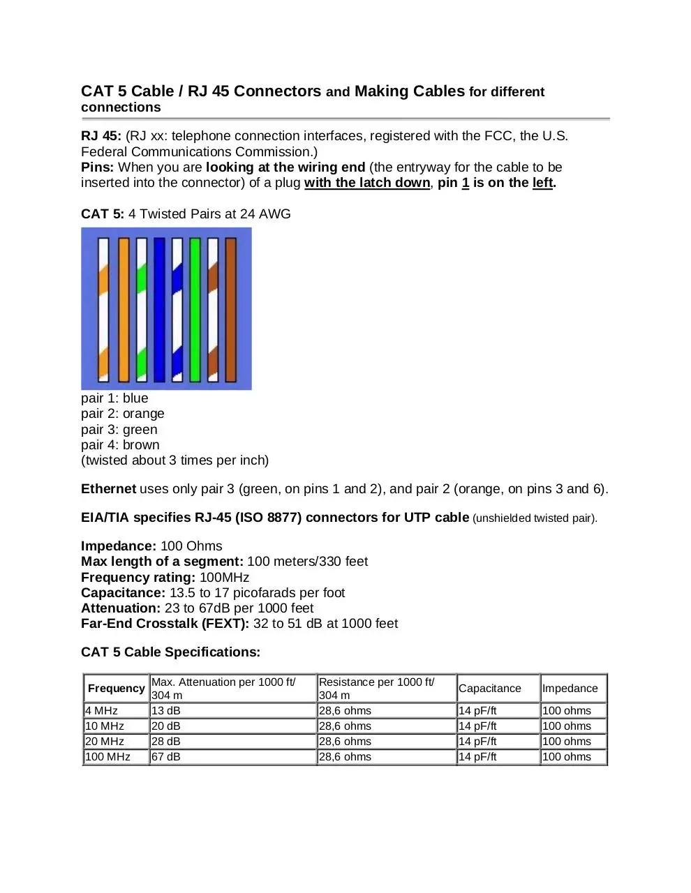
CAT 5: 4 Twisted Pairs at 24 AWG
pair 1: blue
pair 2: orange
pair 3: green
pair 4: brown
(twisted about 3 times per inch)
Ethernet uses only pair 3 (green, on pins 1 and 2), and pair 2 (orange, on pins 3 and 6).
EIA/TIA specifies RJ-45 (ISO 8877) connectors for UTP cable (unshielded twisted pair).
Impedance: 100 Ohms
Max length of a segment: 100 meters/330 feet
Frequency rating: 100MHz
Capacitance: 13.5 to 17 picofarads per foot
Attenuation: 23 to 67dB per 1000 feet
Far-End Crosstalk (FEXT): 32 to 51 dB at 1000 feet
CAT 5 Cable Specifications:
Frequency
4 MHz
10 MHz
20 MHz
100 MHz
Max. Attenuation per 1000 ft/
304 m
13 dB
20 dB
28 dB
67 dB
Resistance per 1000 ft/
304 m
28,6 ohms
28,6 ohms
28,6 ohms
28,6 ohms
Capacitance
Impedance
14 pF/ft
14 pF/ft
14 pF/ft
14 pF/ft
100 ohms
100 ohms
100 ohms
100 ohms
How to make a “good” CAT5 Cable.
A good CAT5 termination provides you a connection that has the following important
characteristics: a proper wire crimp, a wire insulation strain relief crimp and a cable strain relief crimp.
REMEMBER – To avoid NEXT and FEXT problems, it is also important to not unwind the wires more
than necessary. Conversely, while maintaining the twists as far as possible is important, don't let it stop you
from inserting the wires as far as possible. I've made a lot of these cables personally, and this is how I do it:
* Strip the cables Jacket back one full inch.
* Untwist the wires back to within 1/8" of the jacket.
* Arrange the wires in the order in which you want to crimp them, (ie. 568A, 568B, etc.) .
* Grasp the wires firmly, between your thumb and forefinger, flatten them, and even wiggle them a bit, to
take out the curliness, (concentrate your efforts on the bottom 1/2") the wires must lay flat and together,
aligned as close as possible.
* While holding the wires firmly, cut off the the wires 1/2" from the cables jacket (Cut the wires with some
sharp wire strippers or even high quality scissors, avoid wire cutters that flatten the ends of the wires
insulating material, this makes stuffing the wires very difficult.)
* Stuff the wires into the connector, making sure the wires stay lined up. NOTE: The wires should reach the
end of the little tube they are in, if possible, or at least past the farthest point of that "little funny Gold Plated
thingy" above it, which will terminate it.
* The jacket should go even with the end of the first indent, if possible, as it's a strain relief for the cable.
* Insert it into the crimping tool, and Crimp it! All of this is very dependant on the tools you are using, the
connectors you are using, and the cable you are using. A bad combination can be hell!
How to wire a CAT5 (EIA 568-B*) Cable.
connector #1
1 WHT/ORG
2 ORG/WHT
3 WHT/GRN
4 BLU/WHT
5 WHT/BLU
6 GRN/WHT
7 WHT/BRN
8 BRN/WHT
connector #2
1 WHT/ORG
2 ORG/WHT
3 WHT/GRN
4 BLU/WHT
5 WHT/BLU
6 GRN/WHT
7 WHT/BRN
8 BRN/WHT
How to wire a CAT5 (EIA 568-A*) Cable.
connector #1
1 WHT/GRN
2 GRN/WHT
3 WHT/ORG
4 BLU/WHT
5 WHT/BLU
6 ORG/WHT
7 WHT/BRN
8 BRN/WHT
connector #2
1 WHT/GRN
2 GRN/WHT
3 WHT/ORG
4 BLU/WHT
5 WHT/BLU
6 ORG/WHT
7 WHT/BRN
8 BRN/WHT
*The real difference between 568A and 568B is that the White/Orange-Orange/White and White/Green-Green/White pairs are
swapped.
Crimp strain relief:
Cable jacket should be inserted past the strain relief crimp (see picture).
How to wire a "Crossover" Cable.
(EIA 568-B*)
connector #1
1 WHT/ORG
2 ORG/WHT
3 WHT/GRN
4 BLU/WHT
5 WHT/BLU
6 GRN/WHT
7 WHT/BRN
8 BRN/WHT
connector #2
1 WHT/GRN
2 GRN/WHT
3 WHT/ORG
4 BLU/WHT
5 WHT/BLU
6 ORG/WHT
7 BRN/WHT
8 WHT/BRN
USOC crossover cables are like this:
1 WHT/BRN
2 WHT/GRN
3 WHT/ORG
4 WHT/BLU
5 BLU/WHT
6 ORG/WHT
7 GRN/WHT
8 BRN/WHT
8 WHT/BRN
7 WHT/GRN
6 WHT/ORG
5 WHT/BLU
4 BLU/WHT
3 ORG/WHT
2 GRN/WHT
1 BRN/WHT
10BaseT and 100BaseT Cross Cable
C1 Pins
1
2
3
4
5
6
7
8
Color Code
White/Orange
Orange
White/Green
Blue
White/Blue
Green
White/Brown
Brown
Color Code
White/Green
Green
White/Orange
Blue
White/Blue
Orange
White/Brown
Brown
C2 Pins
1
2
3
4
5
6
7
8
color abbreviations:
WHT-WHITE
BRN-BROWN
ORG-ORANGE
GRN-GREEN
BLU-BLUE
The first color listed in the color pair is dominant color of the wire.
In other words, WHT/ORG is a white wire with orange stripes.
ISDN BRI RJ45 Standard (574616-MO97):
RJ 45 Pin
1
2
Pair
3
4
5
6
Tx+
Rx +
Rx -
Tx -
4
5
6
Rx -
Tx -
7
8
7
8
ISDN PRI RJ45 Standard (574616-MO97):
RJ 45 Pin
1
2
Pair
Tx+
Rx +
3
(T1 PRI X-Over = Essentially, tie Pins 1[connector 1] – P4[connector 2] and
P2[connector 1] – P5[connector2], …then… Pins 1[connector 2] – P4[connector 1] and
P4[connector 2] – P5[connector1])
10BaseT and 100BaseT Cross Cable
C1 Pins
1
2
3
4
5
6
7
8
Color Code
White/Orange
Orange
White/Green
Blue
White/Blue
Green
White/Brown
Brown
Color Code
White/Green
Green
White/Orange
Blue
White/Blue
Orange
White/Brown
Brown
C2 Pins
1
2
3
4
5
6
7
8
(Ethernet X-Over = Essentially, tie Pins 1[connector 1] – P2[connector 2] and
P3[connector 1] – P6[connector2], …then …Pins 1[connector 2] – P2[connector 1] and
P3[connector 2] – P6[connector1])
Cat5 Wiring Standards, Listed
10Base-T 100Base-TX
AT&T 258A,
10Mbps
100Mbps
EIA/TIA 568B
Cat3
Cat5
1
white/green
white/orange TX+
TX+
2
green/white
orange/white TXTX3
white/orange
white/green
RX+
RX+
4
blue/white
blue/white
na
na
5
white/blue
white/blue
na
na
6
orange/white
green/white
RXRX7
white/brown
white/brown na
na
8
brown/white
brown/white na
na
BI=BI directional data RX=Receive Data TX=Transmit Data
Pin
EIA/TIA 568A
100Base-T4
100Mbps
Cat3
TX D1+
TX D1RX D2+
BI D3+
BI D3RX D2BI D4+
BI D4-
100Base-T2
100Mbps
Cat3
BI DA+
BI DABI DB+
na
na
BI DBna
na
1000Base-T
1Gbps
Cat5+
BI DA+
BI DABI DB+
BI DC+
BI DCBI DBBI DD+
BI DD-
Testing CAT5 Cable
Since the Cat 5 cable is used to the fullest extent of its performance envelope, testing is very important.
There are four basic tests that are called for as part of the EIA/TIA specs for all UTP cables: wiremap,
length, attenuation and crosstalk. Let's take a look at each of them.
Wiremap
Wiremapping simply means that each wire is hooked up correctly, with no open wires or shorts. That's
mostly very straightforward. Each pair must be connected to the correct pins at the plugs and jacks, with
good contacts in the terminations (called "IDC" or insulation-displacement connections, by the way, since
the wires are held in knife-edge terminations that slice through the insulation and dig into the copper wire,
forming a tight seal.)
Most of the failures are simple enough to understand, like reversed wires in a pair, crossed pairs or opens
and shorts. One possible failure is crossed pairs, caused when both wires of a pair are crossed at one
termination. The usual cause of a crossed pair is a 568A termination on one end and a 568B on the other.
The most difficult wiremap problem is a split pair, when one wire on each pair is reversed on both ends.
The usual wiremap will pass but crosstalk will fail. It takes a Cat 5 tester or a more sophisticated
wiremapper to find a split pair, as most wiremappers do not check crosstalk.
Length
Since 568 cables must be less than 90 meters (296 feet) in the link and 100 meters in the channel (328
feet), length must be tested. This is done with a "time domain reflectometer" which is a fancy term for
cable "radar". The tester sends out a pulse, waits for an "echo" from the far end and measures the time it
took for the trip. Knowing the speed in the cable, it calculates the length.
If you have a short or open, the TDR will tell you where the problem is too, making it a great tool for
finding problems.
Attenuation
The proper operation of a LAN on the cable plant requires the signal strength be high enough at the
receiver end. Thus the attenuation of the cable is very important. Since LANs send high speed signals
through the cable and the attenuation is variable with the frequency of the signal, the fancy automated
testers test attenuation at several wavelengths specified in the 568 specs (TSB-67 to be exact).
This test requires a tester at each end of the cable, one to send and one to receive, then one of them will
calculate the loss and record it. There are pass fail criteria for the cable at Cat 3, 4 and 5 max
frequencies.
Crosstalk (NEXT)
It's called NEXT for "near end cross talk" since it measures the crosstalk (signal coupled from one pair to
another) at the end where one pair is transmitting (and the transmitted signal is largest causing the most
crosstalk.) Crosstalk is minimized by the twists in the cable, with different twist rates causing each pair to
be antennas sensitive to different frequencies and hopefully not picking up the signals from it's
neighboring pairs. Remember what we said: you MUST keep the twists as close to the terminations as
possible to minimize crosstalk.
Cat 5 testers measure crosstalk from one pair to all three other pairs for each pair and compare it to the
568 specs, giving a pass/fail result. Some also calculate "ACR" or attenuation/crosstalk ratio, as it is a
measure of how big the crosstalk signal is to the attenuated signal at the receiver. You want this number
as big as possible, as it is an indication of the signal to noise ratio.
More Tests Coming Soon!
The next generation of test specs will probably include a number of new tests to insure higher
performance from the cable. These tests relate to higher bandwidth usage of the cable and simultaneous
use of all four pairs, perhaps even in both directions at once! Powersum NEXT is the NEXT on one pair
when all three others are carrying signals. This is realistic with Fast Ethernet and Gigabit Ethernet where
all pairs carry signals, often simultaneously. Manufacturers routinely test cables for this characteristic
now, but there is no standard yet for the performance of the cable or terminations. FEXT is far end
crosstalk, looking at the effect of the coupling from one pair to another over the entire length, measured at
the far end. ELFEXT is equal level FEXT, or the ratio of FEXT to attenuation, sort of like ACR.
Delay Skew measures how much simultaneous pulses spread out at the far end. This measures the
speed on each pair, which may be different due to the variations in number of twists (more twists means
longer wires) or insulation. Return loss is a measure of the reflections from the cable due to variations in
the impedance. These reflections can cause signal degradation, especially if the pairs are used in a fullduplex (bidirectional) mode.
Testers
UTP testers are mostly automated, push a button get a pass/fail simple. Wiremappers test the
connections and Cat 5 testers test the performance at high frequencies. In fact, Cat 5 testers test
everything, wiremap, length, attenuation and crosstalk in one connection, give you a pass/fail result,
some help on troubleshooting, store the result and practically everything else but make coffee.
Some installers use the Cat 5 tester for all testing, after the cable is installed. Others have each crew use
an inexpensive wiremapper to make sure connections are correct before the Cat 5 tester is brought in,
since it's a very expensive unit that needs a trained operation and many failures are simply wire map
problems. By having each crew find and fix their own wiremap problems, testing and corrections are done
as the cable is installed and the cost of the Cat 5 tester is not wasted on simple problems. It just provides
the high frequency tests and documentation required by most users. Buying a Cat 5 tester today is a bit of
a crap-shoot, since everybody knows the 568 spec will be upgraded to include more tests at higher
frequencies soon, but nobody knows exactly how far. 155 MHz, 200 MHz, 250 MHz, higher? The best bet
is to not buy a unit that is not already rated to higher frequencies or that cannot be upgraded easily!
What The Heck Is A Certified Cable?
Did the cable pass an exam and get a certificate? Well, sort of. This term has been used by vendors
of testers to mean that the cable was tested and passed by one of the Cat 5 testers. It means that it
meets the minimum specifications of TSB067 and should work with any network designed to operate on a
Cat 5 link.
This information researched and provided by Communication Design Group….912-786-0068
Download How to make a CAT5 Cable
How to make a CAT5 Cable.pdf (PDF, 140.28 KB)
Download PDF
Share this file on social networks
Link to this page
Permanent link
Use the permanent link to the download page to share your document on Facebook, Twitter, LinkedIn, or directly with a contact by e-Mail, Messenger, Whatsapp, Line..
Short link
Use the short link to share your document on Twitter or by text message (SMS)
HTML Code
Copy the following HTML code to share your document on a Website or Blog
QR Code to this page

This file has been shared publicly by a user of PDF Archive.
Document ID: 0000222423.