variklis (PDF)
File information
Title: -J05483
Author: Dept 625 Service Communications
This PDF 1.4 document has been sent on pdf-archive.com on 03/09/2015 at 14:04, from IP address 78.61.x.x.
The current document download page has been viewed 1133 times.
File size: 7.19 MB (18 pages).
Privacy: public file


File preview
-J05483
REV. 2011-06-10
SE120R SCREAMIN' EAGLE PRO RACE-USE CRATE ENGINE
1999-2005 models require separate purchase of symmetric
intake seal flanges (Part No. 26993-06), quantity 2.
GENERAL
Kit Number
•
Installation of compression releases is required. Refer to
Screamin' Eagle Pro Catalog or contact a Harley-Davidson
dealer.
For model fitment information, see the P&A Retail Catalog or
the Parts and Accessories section of www.harley-davidson.com
(English only).
•
Clutch kit that will support a minimum of 140 ft-lbs of
torque.
•
SE throttle body, Air Cleaner and High Flow injectors.
Refer to the Screamin' Eagle Pro Catalog or contact a
Harley-Davidson dealer.
Installation of this kit requires jetting changes or recalibration for proper function. Failure to do so may cause a
lean fuel condition, which may result in engine damage.
(00623b)
•
SE exhaust gaskets kit (Part No. 17048-98).
•
Oil cooler is recommended. See P&A Retail Catalog or
the Parts and Accessories section of www.harley-davidson.com.
NOTES
•
This engine is for race use only! You must remove the emissions label and license plate from the factory chassis.
For EFI Models: SE Pro Super Tuner - refer to Screamin'
Eagle Pro Catalog or contact a Harley-Davidson dealer.
•
See appropriate sections in service manual for the special
tools required to install this kit.
19289-12
Models
This engine has been assembled with a Dyna Sprocket Shaft
Spacer (Part No. 24038-03).
KIT CONTENTS
See Figure 7 through Figure 13 and Table 13 through Table
19.
Additional Parts Required
•
Recommended synthetic engine oil, Screamin' Eagle
SYN3® 20W50 (Part No. 99824-03/00QT).
•
Touring models require replacement of Sprocket Shaft
Spacer with Part No. 24008-03 for 2002-2005 models or
Part No. 24009-06 for 2006 models.
•
The cylinder heads in this kit are machined for use with
symmetric intake flanges (original equipment since 2006).
The rider's safety depends upon the correct installation
of this kit. Use the appropriate service manual procedures.
If the procedure is not within your capabilities or you do
not have the correct tools, have a Harley-Davidson dealer
perform the installation. Improper installation of this kit
could result in death or serious injury. (00333a)
NOTE
This instruction sheet references service manual information.
A service manual for your model motorcycle is required for this
installation and is available from a Harley-Davidson dealer.
PREPARATION
NOTE
For vehicles equipped with security siren:
•
Verify that the Hands-Free Fob is present.
•
Turn the ignition key switch to IGNITION.
For EFI Models:
To prevent spray of fuel, purge system of high-pressure
fuel before supply line is disconnected. Gasoline is
extremely flammable and highly explosive, which could
result in death or serious injury. (00275a)
Follow service manual instructions to purge the fuel supply of
high pressure gasoline and remove the fuel supply line.
-J05483
Many Harley-Davidson® Parts & Accessories are made of plastics and metals which can be recycled.
Please dispose of materials responsibly.
1 of 18
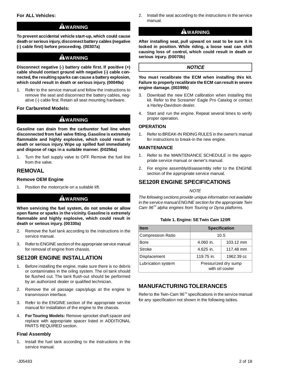
For ALL Vehicles:
To prevent accidental vehicle start-up, which could cause
death or serious injury, disconnect battery cables (negative
(-) cable first) before proceeding. (00307a)
Disconnect negative (-) battery cable first. If positive (+)
cable should contact ground with negative (-) cable connected, the resulting sparks can cause a battery explosion,
which could result in death or serious injury. (00049a)
1.
Refer to the service manual and follow the instructions to
remove the seat and disconnect the battery cables, negative (-) cable first. Retain all seat mounting hardware.
2.
After installing seat, pull upward on seat to be sure it is
locked in position. While riding, a loose seat can shift
causing loss of control, which could result in death or
serious injury. (00070b)
You must recalibrate the ECM when installing this kit.
Failure to properly recalibrate the ECM can result in severe
engine damage. (00399b)
3.
Download the new ECM calibration when installing this
kit. Refer to the Screamin' Eagle Pro Catalog or contact
a Harley-Davidson dealer.
4.
Start and run the engine. Repeat several times to verify
proper operation.
For Carbureted Models:
Gasoline can drain from the carburetor fuel line when
disconnected from fuel valve fitting. Gasoline is extremely
flammable and highly explosive, which could result in
death or serious injury. Wipe up spilled fuel immediately
and dispose of rags in a suitable manner. (00256a)
1.
Turn the fuel supply valve to OFF. Remove the fuel line
from the valve.
REMOVAL
Remove OEM Engine
1.
3.
OPERATION
1.
Refer to BREAK-IN RIDING RULES in the owner's manual
for instructions to break-in the new engine.
MAINTENANCE
1.
Refer to the MAINTENANCE SCHEDULE in the appropriate service manual or owner's manual.
2.
For engine assembly/disassembly refer to the ENGINE
section of the appropriate service manual.
SE120R ENGINE SPECIFICATIONS
Position the motorcycle on a suitable lift.
When servicing the fuel system, do not smoke or allow
open flame or sparks in the vicinity. Gasoline is extremely
flammable and highly explosive, which could result in
death or serious injury. (00330a)
2.
Install the seat according to the instructions in the service
manual.
Remove the fuel tank according to the instructions in the
service manual.
Refer to ENGINE section of the appropriate service manual
for removal of engine from chassis.
SE120R ENGINE INSTALLATION
1.
Before installing the engine, make sure there is no debris
or contaminates in the oiling system. The oil tank should
be flushed out. The tank flush-out should be performed
by an authorized dealer or qualified technician.
2.
Remove the oil passage caps/plugs at the engine to
transmission interface.
3.
Refer to the ENGINE section of the appropriate service
manual for installation of the engine to the chassis.
4.
For Touring Models: Remove sprocket shaft spacer and
replace with appropriate spacer listed in ADDITIONAL
PARTS REQUIRED section.
NOTE
The following sections provide unique information not available
in the service manual ENGINE section for the appropriate Twin
Cam 96™ alpha engines from Touring or Dyna platforms.
Table 1. Engine: SE Twin Cam 120R
Item
Specification
Compression Ratio
Bore
10.5
4.060 in.
103.12 mm
Stroke
4.625 in.
117.48 mm
Displacement
119.75 in.
1962.39 cc
Lubrication system
Pressurized dry sump
with oil cooler
MANUFACTURING TOLERANCES
Refer to the Twin-Cam 96™ specifications in the service manual
for any specification not shown in the following tables.
Final Assembly
1.
Install the fuel tank according to the instructions in the
service manual.
-J05483
2 of 18
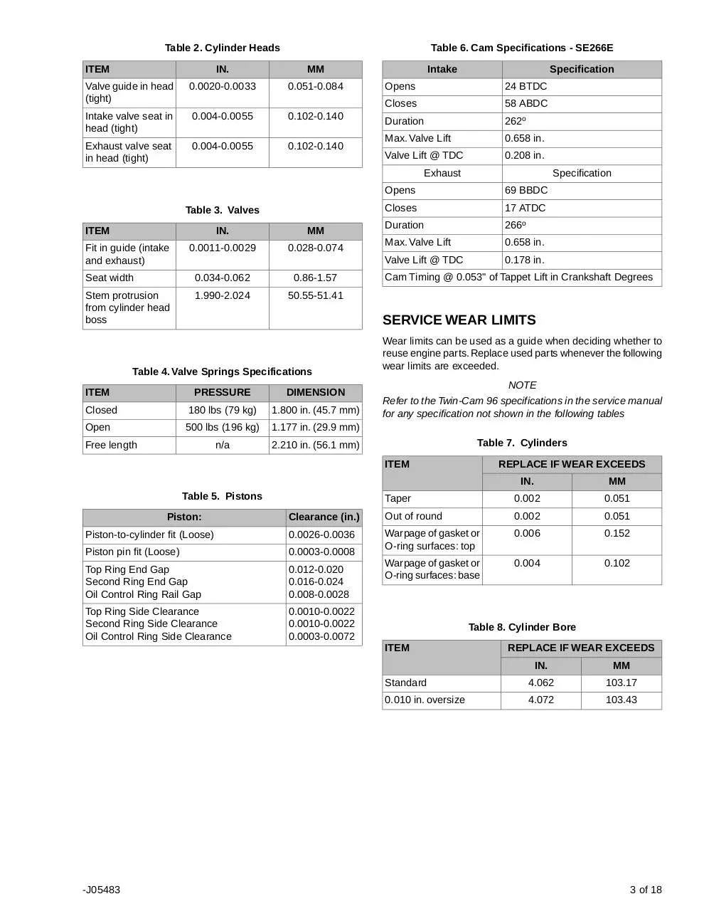
Table 2. Cylinder Heads
ITEM
Table 6. Cam Specifications - SE266E
IN.
MM
Valve guide in head
(tight)
0.0020-0.0033
0.051-0.084
Intake valve seat in
head (tight)
0.004-0.0055
0.102-0.140
Exhaust valve seat
in head (tight)
0.004-0.0055
0.102-0.140
Intake
Specification
Opens
24 BTDC
Closes
58 ABDC
Duration
262o
Max. Valve Lift
0.658 in.
Valve Lift @ TDC
0.208 in.
Exhaust
Table 3. Valves
ITEM
Fit in guide (intake
and exhaust)
IN.
MM
0.0011-0.0029
0.028-0.074
Seat width
0.034-0.062
0.86-1.57
Stem protrusion
from cylinder head
boss
1.990-2.024
50.55-51.41
Opens
69 BBDC
Closes
17 ATDC
Duration
266o
Max. Valve Lift
0.658 in.
Valve Lift @ TDC
0.178 in.
Cam Timing @ 0.053" of Tappet Lift in Crankshaft Degrees
SERVICE WEAR LIMITS
Table 4. Valve Springs Specifications
ITEM
Specification
PRESSURE
DIMENSION
Closed
180 lbs (79 kg)
1.800 in. (45.7 mm)
Open
500 lbs (196 kg)
1.177 in. (29.9 mm)
n/a
2.210 in. (56.1 mm)
Free length
Wear limits can be used as a guide when deciding whether to
reuse engine parts. Replace used parts whenever the following
wear limits are exceeded.
NOTE
Refer to the Twin-Cam 96 specifications in the service manual
for any specification not shown in the following tables
Table 7. Cylinders
ITEM
REPLACE IF WEAR EXCEEDS
IN.
MM
Taper
0.002
0.051
Clearance (in.)
Out of round
0.002
0.051
Piston-to-cylinder fit (Loose)
0.0026-0.0036
0.006
0.152
Piston pin fit (Loose)
0.0003-0.0008
Warpage of gasket or
O-ring surfaces: top
Top Ring End Gap
Second Ring End Gap
Oil Control Ring Rail Gap
0.012-0.020
0.016-0.024
0.008-0.0028
Warpage of gasket or
O-ring surfaces: base
0.004
0.102
Top Ring Side Clearance
Second Ring Side Clearance
Oil Control Ring Side Clearance
0.0010-0.0022
0.0010-0.0022
0.0003-0.0072
Table 5. Pistons
Piston:
Table 8. Cylinder Bore
ITEM
-J05483
REPLACE IF WEAR EXCEEDS
IN.
MM
Standard
4.062
103.17
0.010 in. oversize
4.072
103.43
3 of 18
is03183
Table 9. Pistons
Piston-to-cylinder fit (Loose)
2
Wear Limit (in.)
Fit in cylinder (Loose)
0.0061
Piston Pin Fit (Loose)
0.0011
Top Ring End Gap
Second Ring End Gap
Oil Control Ring Rail Gap
0.030
0.034
0.038
Top Ring Side Clearance
Second Ring Side Clearance
Oil Control Ring Side Clearance
0.0030
0.0030
0.0079
1
SERVICING OR REPLACING SE120R
CYLINDERS
1.
NOTE
If vehicle is equipped with Harley-Davidson Smart Security
System, see owner's manual for instructions to disarm the
system.
2.
1. Gasket, cylinder base
2. Gasket, cylinder head
Position motorcycle on a suitable lift.
Remove seat according to the instructions in the service
manual.
When servicing the fuel system, do not smoke or allow
open flame or sparks in the vicinity. Gasoline is extremely
flammable and highly explosive, which could result in
death or serious injury. (00330a)
3.
Remove main fuse. Refer to service manual for your
motorcycle.
4.
Remove fuel tank according to the instructions in the service manual.
Figure 1. Cylinder Gaskets
Final Assembly
2.
Install the fuel tank according to the instructions in the
service manual.
3.
Refer to the service manual to install the main fuse.
4.
Install the seat according to the instructions in the service
manual.
After installing seat, pull upward on seat to be sure it is
locked in position. While riding, a loose seat can shift
causing loss of control, which could result in death or
serious injury. (00070b)
Remove Engine Components
SERVICING OR REPLACING SE120R
PISTON
1.
Refer to service manual to remove existing air cleaner
assembly.
1.
2.
Remove the existing exhaust system following service
manual procedures.
3.
Disassemble the engine top end. Refer to the appropriate
engine sections in the service manual.
Install Engine Top End Components
Refer to ENGINE section of service manual.
INSTALLATION
To prevent accidental vehicle start-up, which could cause
death or serious injury, disconnect battery cables (negative
(-) cable first) before proceeding. (00307a)
NOTES
See Figure 1. The 4.060 in. cylinder base gasket (1) and cylinder head gasket (2) eliminate the need for O-rings. Do not
use O-rings on cylinder dowels or cylinder spigots.
When installing new base gasket (1), install with the embossed
side down and the concave side up.
Disconnect negative (-) battery cable first. If positive (+)
cable should contact ground with negative (-) cable connected, the resulting sparks can cause a battery explosion,
which could result in death or serious injury. (00049a)
1.
1.
Refer to the appropriate service manual and assemble
the engine with the following changes:
a.
-J05483
Assemble the top end of the engine using the base
gaskets and head gaskets provided in the kit. Refer
to the appropriate engine section in the service
manual.
Refer to the service manual and follow the instructions
given to remove the seat and disconnect the battery
cables, negative cable first.
4 of 18
Table 10. Specifications
When servicing the fuel system, do not smoke or allow
open flame or sparks in the vicinity. Gasoline is extremely
flammable and highly explosive, which could result in
death or serious injury. (00330a)
2.
Refer to the ENGINE: STRIPPING MOTORCYCLE FOR
SERVICE and TOP END OVERHAUL, DISASSEMBLY
sections of the service manual for cylinder head, cylinder
and piston removal procedures.
3.
Follow the procedures in the ENGINE: SUBASSEMBLY
SERVICE AND REPAIR, TOP END/ CYLINDER/ UPPER
CONNECTING ROD sections of the service manual for
inspection of parts.
4.
See the ENGINE: SUBASSEMBLY SERVICE AND
REPAIR, CYLINDER section of the service manual for
boring and honing instructions.
NOTES
Install the top ring (barrel-faced) and second ring (taper-faced
Napier) with the "N" marking facing up. Oil ring rails can be
installed either side up.
The 4.060 inch cylinder base gaskets and cylinder head gaskets included in the kit eliminate the need for O-rings (Part No.
11273). Do not use O-rings on cylinder dowels or cylinder
spigots.
When installing new base gasket, install with the embossed
side down and the concave side up.
is06326
Piston:
Clearance (in.)
Piston-to-cylinder fit (Loose)
0.0026-0.0036
Piston pin fit (Loose)
0.0003-0.0008
Top Ring End Gap
Second Ring End Gap
Oil Control Ring Rail Gap
0.012-0.020
0.016-0.024
0.008-0.0028
Top Ring Side Clearance
Second Ring Side Clearance
Oil Control Ring Side Clearance
0.0010-0.0022
0.0010-0.0022
0.0003-0.0072
Table 11. Service Wear Limits
Piston-to-cylinder fit (Loose)
Wear Limit (in.)
Fit in cylinder (Loose)
0.0061
Piston Pin Fit (Loose)
0.0011
Top Ring End Gap
Second Ring End Gap
Oil Control Ring Rail Gap
0.030
0.034
0.038
Top Ring Side Clearance
Second Ring Side Clearance
Oil Control Ring Side Clearance
0.0030
0.0030
0.0079
PISTON PIN RETAINING RING (CIRCLIP)
INSTALLATION
NOTE
Circlip gap must be at 12 or 6 o'clock position when installed.
1.275”
2
8.
See Figure 3. Insert the open end of the circlip (1) into the
notch (2) on the groove (3) around the piston pin boss so
that the gap is at the 12 or 6 o'clock position when
installed.
2
1
is02626
1
3
1. Piston width
2. Measurement area
Figure 2. Piston Measurements
NOTE
Checking piston-to-cylinder fit at this location per table 20 is
for reference.
5.
See Figure 2. Measure the piston width (1), 90 degrees
horizontally from both sides of the piston pin hole and
1.275 in. down from the deck surface (top) of the piston
(2). See table 20 for piston-to-cylinder fit at this location.
6.
The pistons in this kit are front and rear specific. Install
the piston marked "FRONT" in the front cylinder with the
arrow pointing towards the front of the engine. Install the
piston marked "REAR" in the rear cylinder with the arrow
pointing towards the front of the engine.
7.
Refer to the ENGINE: TOP END OVERHAUL, ASSEMBLY
section of the service manual for piston, cylinder and cylinder head installation procedures.
-J05483
2
1. Circlip
2. Notch
3. Groove
Figure 3. Circlip and Piston
5 of 18
is06003b
is02627
2
1
3
4
5
1. Thumb orientation
2. Circlip 85% seated
1
2
Figure 4. Install Circlip
9.
See Figure 4. Position your thumb (1) as shown, and press
firmly until approximately 85% of the circlip (2) is seated
in the groove.
Figure 5. Piston Assembly
10. Being careful not to scratch or mar the piston, use a smallbladed screwdriver to wedge the circlip into the remainder
of the groove. Repeat for the remaining circlips.
Table 12. Piston Assembly
Item
NOTE
Make sure the piston circlip is fully seated, or ENGINE
DAMAGE WILL OCCUR.
11. Refer to the ENGINE: ASSEMBLING MOTORCYCLE
AFTER STRIPPING section of the service manual for final
re-assembly procedures.
Description (Quantity)
1
Piston (front, standard)
2
Piston (rear, standard)
3
•
Ring set, standard (2)
4
•
Piston pin (2)
5
•
Circlip (4)
1
Piston (front, +0.010)
2
Piston (rear, +0.010)
3
•
Ring set, +0.010 (2)
4
•
Piston pin (2)
5
•
Circlip (4)
REPLACING/SERVICING PUSHRODS
1.
Refer to ENGINE section of service manual.
NOTES
Follow the appropriate service manual procedures for installing
and removing the pushrods. The pushrods are marked Intake
and Exhaust.
The pushrods are directional. Be sure the larger end of the
pushrods are installed down in the lifter sockets.
-J05483
6 of 18
is06297
1
2
4
1.
2.
3.
4.
3
Rocker cover assembly
Rocker arm support plate assembly
Rear intake pushrod
Rear exhaust pushrod
Figure 6. Push Rods
-J05483
7 of 18
SERVICE PARTS
is06774b
1
Figure 7. Engine Assembly, SE120R Complete
Table 13. SE120R Screamin' Eagle Pro Race-Use Crate Engine
Item
1
Description (Quantity)
Engine assembly, complete
-J05483
Part Number
19289-12
8 of 18
is06380a
4
3
2
1
5
Figure 8. Service Parts: SE120R Screamin' Eagle Pro Race-Use Crate Engine
Table 14. Service Parts: SE120R Screamin' Eagle Pro Race-Use Crate Engine
Item
Description (Quantity)
Part Number
1
Base gasket, cylinder (2)
16736-04
2
SE cylinder kit, 4.060 in., (black) (includes items 1, 3, 4, 1105 and 1086A)
16550-04C
3
Dowel pin, ring (4)
16595-99A
4
Gasket, cylinder head (2)
16104-04
5
Stud, cylinder (8)
16834-99A
6
Gasket kit, engine overhaul (does not include cylinder head gasket, base gasket or valve stem
seals) (Not Shown)
17053-99C
7
Gasket kit, top-end, (does not include cylinder head gasket, base gasket or valve stem seals)
(Not Shown)
17052-99C
-J05483
9 of 18
Download variklis
variklis.pdf (PDF, 7.19 MB)
Download PDF
Share this file on social networks
Link to this page
Permanent link
Use the permanent link to the download page to share your document on Facebook, Twitter, LinkedIn, or directly with a contact by e-Mail, Messenger, Whatsapp, Line..
Short link
Use the short link to share your document on Twitter or by text message (SMS)
HTML Code
Copy the following HTML code to share your document on a Website or Blog
QR Code to this page

This file has been shared publicly by a user of PDF Archive.
Document ID: 0000299384.