Q117R1 (PDF)
File information
Title: Microsoft Word - Q117-R1update.doc
Author: dpelcher
This PDF 1.5 document has been generated by PScript5.dll Version 5.2 / GNU Ghostscript 7.05, and has been sent on pdf-archive.com on 08/10/2015 at 16:04, from IP address 70.125.x.x.
The current document download page has been viewed 2756 times.
File size: 970.13 KB (2 pages).
Privacy: public file

File preview
SVE BULLETIN
SPECIAL VEHICLE ENGINEERING – BODY BUILDERS ADVISORY SERVICE
Toll-free: (877) 840-4338
E-Mail: bbasqa@ford.com (preferred)
Fax:
Website: www.fleet.ford.com/truckbbas
(313) 594-2633
QVM Bulletin: Q-117-R1
Date: June 7, 2007
2008 F-Series Super Duty Upfitter Switches
Models Affected All 2008 Model Year F-250/350/450/550.
Purpose
To utilize Ford Upfitter Switches on F-Series Super Duty trucks.
Description
The Ford Upfitter Switches are optional instrument panel mount switches (Option Code 66S) that control passenger
side mounted relays. These relays power four blunt cut wires that are taped on a harness near the relay pack that
can be found beneath the instrument panel and to the left of the steering column. The four blunt cut wires are as
follows:
Switches
Aux 1
Aux 2
Aux 3
Aux 4
Circuit
CAC05
CAC06
CAC07
CAC08
Color
Yellow
Green/Brown
Violet/Green
Brown
Fuse
30 Amp
30 Amp
10 Amp
15 Amp
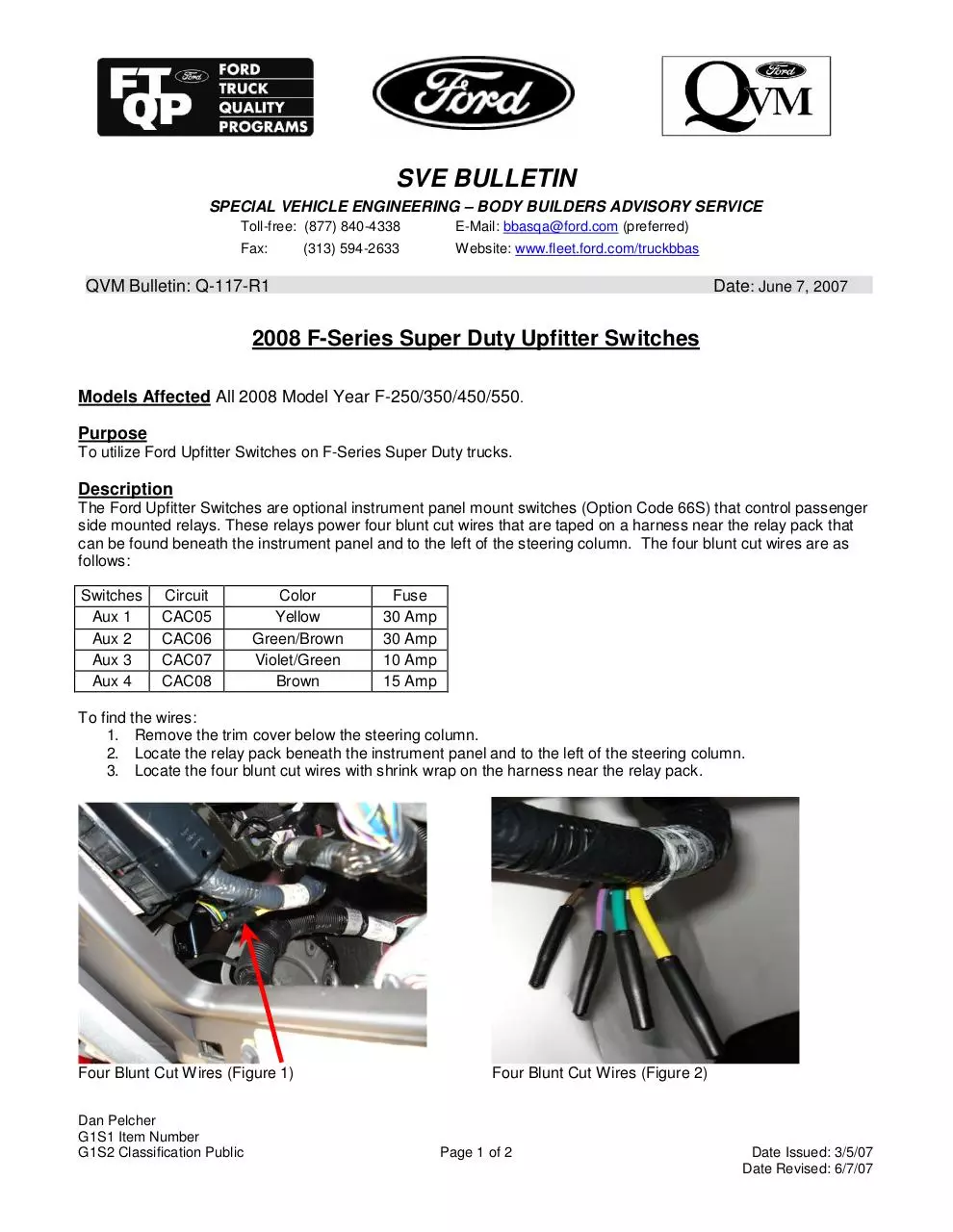
To find the wires:
1. Remove the trim cover below the steering column.
2. Locate the relay pack beneath the instrument panel and to the left of the steering column.
3. Locate the four blunt cut wires with shrink wrap on the harness near the relay pack.
Four Blunt Cut Wires (Figure 1)
Dan Pelcher
G1S1 Item Number
G1S2 Classification Public
Four Blunt Cut Wires (Figure 2)
Page 1 of 2
Date Issued: 3/5/07
Date Revised: 6/7/07
Operating Procedure
The Upfitter Switches are operational when the ignition key is in the "RUN" position only. The power to the switches
is relay controlled and was designed to operate in the "RUN" mode to reduce the possibility of draining the
battery(ies).
Upfitter Switch Wiring Diagram (Figure 3)
If you have any questions, please contact the Ford Truck Body Builders Advisory Service as shown in the header of
this bulletin.
Dan Pelcher
G1S1 Item Number
G1S2 Classification Public
Page 2 of 2
Date Issued: 3/5/07
Date Revised: 6/7/07
Download Q117R1
Q117R1.pdf (PDF, 970.13 KB)
Download PDF
Share this file on social networks
Link to this page
Permanent link
Use the permanent link to the download page to share your document on Facebook, Twitter, LinkedIn, or directly with a contact by e-Mail, Messenger, Whatsapp, Line..
Short link
Use the short link to share your document on Twitter or by text message (SMS)
HTML Code
Copy the following HTML code to share your document on a Website or Blog
QR Code to this page

This file has been shared publicly by a user of PDF Archive.
Document ID: 0000306704.