shoring review including geotech (PDF)
File information
Author: Oracle Reports
This PDF 1.6 document has been generated by Acrobat Pro 15.8.20082, and has been sent on pdf-archive.com on 01/11/2015 at 23:28, from IP address 104.172.x.x.
The current document download page has been viewed 717 times.
File size: 2.05 MB (12 pages).
Privacy: public file


File preview
UCLA Clark Library Seismic Correction
5777 West Century Blvd Suite 1750
Los Angeles, CA 90045
Tel: 310-342-3400 Fax: 310-342-3401
TRANSMITTAL
TRNS-00259
REGENTS UNIVERSITY OF CALIFORNIA
LOS ANGELES-UCLA
Contract #
Project #
Job # 215063
5777 West Century Blvd Suite 1750 Suite 1750
Los Angeles, CA 90045
PH:
Fax:
Date: September 14, 2015
From: Michael Bradwell
Walsh Construction Company II, LLC
929 W Adams Street
Chicago, IL 60607
To: Ken Mand
UNIVERSITY OF CALIFORNIA LOS ANGELES
1060 VETERAN AVE
LOS ANGELES CA 90095
TEL: 310-983-3338
FAX:
Submittal Package Info:
Submittal Package
Number
Description
Excavation Support Systems - Shop Drawings & Monitoring
System
314100-001
Line
Line
314100
Submitted for Approval
Package Sent Via:
Approval
Attached
SUBM-00944
Qty Submittal No.
2
Package
Status
Package Transmitted For:
Qty Submittal No.
1
Spec
Section
SUBM-00945
Review
Cycle
Spec
Section
Sub
Section
1
314100
1.2-B
Review
Cycle
Spec
Section
Sub
Section
1
314100
1.3-B.2
Description
Type
Status
Excavation Support Systems Engineered Shop Drawings
Shop
Drawing
Submitted for Approval
Description
Type
Status
Excavation Supports Systems Monitoring System
Design
Submittal
Submitted for Approval
Due Date: October 5, 2015
CC:
Project Contact:
Project Partner:
Project File
Remarks:
Ken,
Please see attached submittal for approval 314100-001-000 Excavation Support Systems - Shop Drawings & Monitoring Systems.
This submittal contains the following:
1. Engineer Stamped Shop Drawings for Excavation Shoring, Utility Tunneling and Stepped Footing Vertical Shoring
2. Shoring calculations
3. Monitors system for recording horizontal and vertical deflections of excavation shoring
The following items are forthcoming:
1. Installer qualifications - shoring installers will be contracted upon approval of shop drawings. Installer qualifications will meet those outlined in
Specifications and will be submitted at a later date.
Sincerely,
Mike
PROJECT NAME: UCLA
FitnessSeismic
Center Correction
UCLACarnesale
Clark Library
Submittal No: 314100-001-000
Date of Submittal: 09-14-2015
Due Date: 10-05-2015
Specification Section Number and Title: 31 4100 - Excavation Support Systems
Reference to Drawing Sheet Number: N/A
Contractor Name: Walsh Construction Company
Contractor Address: 5777 W. Century Blvd., Los Angeles, CA 90045
Subcontractor Name: N/A
Supplier Name: N/A
Manufacturer Name: N/A
Contract certifies the submittal has been reviewed, verified materials and field measurements and
conditions; and compliance of the information within the submittal meets the requirements of the
Work and of the Contract Documents.
X REVIEWED
APPROVED
Review is only for general conformance of the submittal with information given
and the design concept expressed in the Contract Documents. Comments
made during this review do not relieve the Contractor from compliance with the
requirements of those Contract Documents. The Contractor is responsible for
confirming and correlating all quantities, dimensions, site conditions,
construction means, methods, sequences, procedures and the coordination of
all trades.
____ Reviewed
X
____ See Notations
____ Rejected
REVISE AND RESUBMIT DUE:_________________________
CMiC Project Management - wal_sub_pkg_trans_v21
09/15/2015
Response:
C. Smith
____ Revise & Resubmit
APPROVED W/ CHANGES
"Reviewed for general acceptance only. This review does not relieve the Subcontractor of the
responsibility of making the work conform to the requirements of the contract. The Subcontractor is
Signature:
responsible
for all dimensions, correct fabrication, and accurate fit with the work of other trades."
Date
Received:
Signature Date:
RE: Clark Library Shoring Drawings- Submittal 314100-00...
https://outlook.office365.com/owa/#viewmodel=ReadMe...
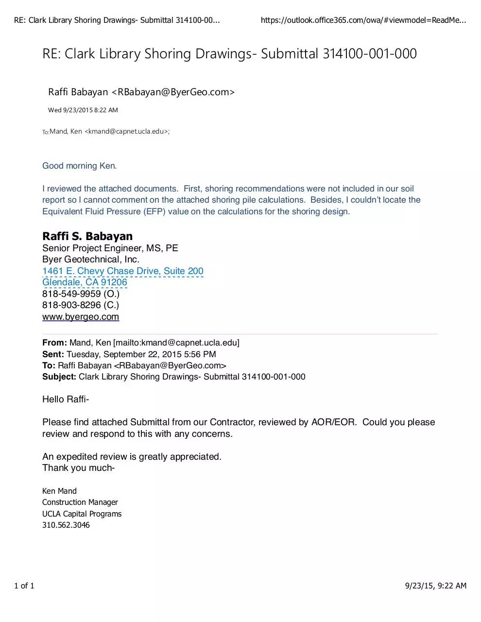
RE: Clark Library Shoring Drawings-‐ Submittal 314100-‐001-‐000
Raffi Babayan <RBabayan@ByerGeo.com>
Wed 9/23/2015 8:22 AM
To:Mand,
Ken <kmand@capnet.ucla.edu>;
Good morning Ken.
I reviewed the attached documents. First, shoring recommendations were not included in our soil
report so I cannot comment on the attached shoring pile calculations. Besides, I couldn’t locate the
Equivalent Fluid Pressure (EFP) value on the calculations for the shoring design.
Raffi S. Babayan
Senior Project Engineer, MS, PE
Byer Geotechnical, Inc.
1461 E. Chevy Chase Drive, Suite 200
Glendale, CA 91206
818-549-9959 (O.)
818-903-8296 (C.)
www.byergeo.com
From: Mand, Ken [mailto:kmand@capnet.ucla.edu]
Sent: Tuesday, September 22, 2015 5:56 PM
To: Raffi Babayan <RBabayan@ByerGeo.com>
Subject: Clark Library Shoring Drawings- Submittal 314100-001-000
Hello RaffiPlease find attached Submittal from our Contractor, reviewed by AOR/EOR. Could you please
review and respond to this with any concerns.
An expedited review is greatly appreciated.
Thank you muchKen Mand
Construction Manager
UCLA Capital Programs
310.562.3046
1 of 1
9/23/15, 9:22 AM
01
S1.0
SHORING PLAN
SCALE:1/4":1.0'
2785 WHITNEY DR.
FAIRFIELD CA 94533
TEL. (415) 889-0878
CLARK LIBRARY
UCLA SHORING
PLAN
UCLA
ABP
08/13/2015
S1.0
16055
ESI: Per excavation shoring notes on
A3.10A and A3.11A, typical vertical
shoring to be 1'-0" clear to existing
foundation and slab on grade construction
CL
CL
CL
TOP OF PILE
2785 WHITNEY DR.
FAIRFIELD CA 94533
TEL. (415) 889-0878
A
S2.0
ESI: Indicate maximum criteria for
sloped and benched excavations
- see excavation and shoring
notes per A3.10A and A3.11A
DETAIL A
SCALE:1":1.0'
CLARK LIBRARY
UCLA SHORING
PLAN
BOTTOM OF EXCAVATION
BOTTOM OF EXCAVATION
B
S2.0
DETAIL B
SCALE:1":1.0'
UCLA
BOTTOM OF PILE
01
S2.0
SHORING SECTION
BOTTOM OF PILE
C
S2.0
DETAIL C
SCALE:1":1.0'
SCALE:1/2":1.0'
ESI: Indicate reinforcing for
drilled pier and anchorage or
embedment for steel pile to
concrete pier
02
S2.0
SHORING ELEVATION
SCALE:1/2":1.0'
ABP
08/13/2015
ESI: Confirm item #7 with
University's Representative
Per KM's email on 9/17: University is okay with
leaving the piles in place, provided that they are
trimmed down to a minimum of 3' below grade and
noted on the as-built drawings.
S2.0
16055
ESI: Typical, coordinate
excavation shoring with
shoring/formwork for suspend
pavilion slab per submittal
031000-001
CL
ESI: Protect
existing stair wall in
place during drilling
for vertical shoring
systems
CL
CL
TOP OF PILE
2785 WHITNEY DR.
FAIRFIELD CA 94533
TEL. (415) 889-0878
A
S3.0
DETAIL A
SCALE:1":1.0'
CLARK LIBRARY
UCLA SHORING
PLAN
BOTTOM OF EXCAVATION
ESI: Following excavation and confirmation of stepped footing
condition at stair wall, submit elevation sketch to University's
Representative showing stepped footing locations and any
locations where steel shoring framing is to remain - University's
Representative (SEOR) will confirm final detailing requirements for
concrete underpinning at stair wall foundation per plan note 8/S2.00
BOTTOM OF EXCAVATION
B
S3.0
DETAIL B
SCALE:1":1.0'
UCLA
BOTTOM OF PILE
BOTTOM OF PILE
C
S3.0
01
S3.0
DETAIL C
SCALE:1":1.0'
STAIR SUPPORT SECTION
02
S3.0
SCALE:1/2":1.0'
STAIR SUPPORT ELEVATION
SCALE:1/2":1.0'
ABP
08/13/2015
D
S3.0
DETAIL D
SCALE:1":1.0'
ESI: Indicate reinforcing for
drilled pier and anchorage or
embedment for steel pile to
concrete pier
S3.0
16055
STRUCTURAL DESIGN AND ANALYSIS
EXCAVATION SHORING
Owner: UCLA
Location: 2520 Cimarron St. Los Angeles CA
CODES
1. ACI 318-11
2. AISC Manual 14th Ed.
3. AWS D1.1
TABLE OF CONTENTS
1. Design of Steel Pile
2. Design of Lagging
3. Design of Horizontal Support
4. Design of Vertical Support
5. Design of Hanger Support
Designed By:
Antonio B Prado Jr., P.E.
Civil Engineer
Lic. #66562
Page
2
4
5
5
6
UCLA Clark Library
Page 2/6
1. Design of Steel Pile
A. Loads
Weight of Soil
Weight of Water
Angle of internal friction, f
Active Soil Pressure Coef.
Passive Soil Pressure Coef.
Surcharge
=
=
=
=
=
=
130.00
62.40
28.00
0.36
2.77
40.00
lbs/ft3
lbs/ft3
deg
B. Materials:
Steel Pile, W10x88: fy
Concrete, fc'
Lagging Timber DF#2: fb
=
=
=
60,000.00
4,000.00
1,200.00
psi
psi
psi
psf
A572
C. Calculate Forces at Bottom of Excavation:
Ground level
Top of pile
H
M
V
Bottom of excavation
Pile spacing, S
Ht. of excavation, H
Due Soil:
Hor. Force, V1
=
=
8.00
14.00
ft.
ft.
=
36,691.20
lbs
Overturning Moment, M1
Due Surcharge:
Hor. Force, V2
=
171,225.60
lbs-ft
=
11,289.60
lbs
Overturning Moment, M2
Total
Hor. Force, V
Overturning Moment, M
=
52,684.80
lbs-ft
=
=
47,980.80
223,910.40
lbs
lbs-ft
D. Analyze Pile:
Length of Pile,L
=
Diameter, D
=
Reinforcement: W10x45
Soil Properties
Young's modulus of soil, E = 7.0 ksi
Prado Engineering
2785 Whitney Dr.
Fairfield CA, 94533
(415) 889-0878
10.00 ft
24.00 in.
August 30, 2015
UCLA Clark Library
Page 3/6
Using OASYS Pile Analys Software, the following results are reported.
General Data
Number of increments = 1
Increment applied loads only
Convergence Control
Maximum number of iterations = 300
Maximum displacement error [in] = 39.371E-6
Maximum pressure error [kip/in²] = 14.503E-6
Damping coefficient = 1.0000
Maximum incremental deflection [in] = 78.742
Soil Data
Elastic-plastic soils
Factor on soil E value: 0.7500
No. Level
E Unit wt. Phi Kq Kc c(top)
dc/dz
[in] [kip/in²] [kip/in³] [deg]
[kip/in²] [kip/in²/in]
1 0.000000 6.9998 224.60 28.000 - - 9.9996E-6
0.99996
Calculated Kq and Kc Values
Node Z/D Kq Kc
1 0.0 4.0943 6.3808
2 2.3333 6.2568 22.373
3 4.6667 7.6365 29.669
4 7.0000 8.5933 33.845
Sections
Name Input Type
Description
Section 1 Explicit
Concrete
Material
Class
Effective EI
[kip-in²]
57.000E+6
Width
[in]
24.000
Pile Properties
Level
Section
[in]
0.0
Section 1
Applied Loads and Displacements
No. Level Force Moment
Displacement
[in]
[kip]
[kip-in]
[in]
1
1
48.000 -2688.0
0.0
Geometry and Initial state
Node Level Soil
EI
1
2
3
4
[in]
0.0
-56.0
-112.00
-168.00
Prado Engineering
2785 Whitney Dr.
Fairfield CA, 94533
(415) 889-0878
1
1
1
1
[kip/in2]
57.000E+6
57.000E+6
57.000E+6
57.000E+6
Effective
Width
[in]
24.000
24.000
24.000
24.000
Water
Pressure
[kip/in²]
0.0
0.0
0.0
0.0
Soil
Disp
[in]
0.0
0.0
0.0
0.0
August 30, 2015
UCLA Clark Library
Page 4/6
Output for load increment 1
Iteration Max
at
Disp
Inc
node error
Disp
[in]
[in]
3
0.34
1
0.0
Node
1
23
4
Level
Defl
[in]
[in]
0.0 -0.34459
56.0 -0.088613
-112.0
0.041033
-168.0
0.11321
Pressure
error
[kip/in²]
0.00
Rotation
[rad]
-0.0058672
-0.0032993
-0.0015941
-0.0011363
Soil
Pressure
Bending
[kip/in²]
[kip-in]
-0.075377
2688.0
-0.019383
2539.4
0.0089756
931.93
0.024764
18.364E-12
1
1
1
1
Shear
[kip]
-48.0
15.679
22.673
0.0
EXTREME values so far:Deflections
Rotations
Moments
Shears
Min
Max
Min
Max
Min
Max
Min
Max
[in]
[in]
[rad]
[rad]
[kip-in]
[kip-in] [kip]
[kip]
-0.34459 0.11321 -0.0058672 -0.0011363 -18.364E-12 2688.0 -48.000 22.673
Max. deflection < 0.5" inch, okay.
E. Check Capacity of Steel Pile:
Mmax
Sx
fb
=
=
=
223,910.40 lbs-ft
4
75.70 in
35,494.38 psi
Use W10x68
Fb = 0.6 x 60,000 = 36,000 psi > fb, okay
2. Design of Lagging
Max. Distributed Load, w
Span, L
Max. Moment, Mmax
Max. Shear, Vmax
=
=
=
=
A. Calculate Maximum Stresses.
Effective width, b
=
Effective depth, d
=
Section Modulus, Sx
=
Max. Bending Stress, fb
=
Max. Shear Stress, fv
D. Allowable Bending Stress:
Unsupported Length, Lu
Effective Depth, d
Lu/d
=
655.20
8.00
5,241.60
2,620.80
lbs/ft (at bottom of excavation)
ft
lbs-ft (wL2/8)
lbs.
(WL/2)
11.50 in.
5.50 in.
3
57.98 in .
(bd2/6)
1,084.86 psi
(M/Sx)
41.44 psi
(V/bd)
Fb' = Fb x CD x CM x Ct x CL x CF x Cfu x Ci x Cr x Cf x Cv
=
=
=
0.00 in.
5.50 in.
0.00
Effective Span, Le
=
16.50 in.
Slenderness ratio, RB
=
1.73
KbE
=
0.44
Prado Engineering
2785 Whitney Dr.
Fairfield CA, 94533
(415) 889-0878
August 30, 2015
Download shoring review including geotech
shoring review including geotech.pdf (PDF, 2.05 MB)
Download PDF
Share this file on social networks
Link to this page
Permanent link
Use the permanent link to the download page to share your document on Facebook, Twitter, LinkedIn, or directly with a contact by e-Mail, Messenger, Whatsapp, Line..
Short link
Use the short link to share your document on Twitter or by text message (SMS)
HTML Code
Copy the following HTML code to share your document on a Website or Blog
QR Code to this page

This file has been shared publicly by a user of PDF Archive.
Document ID: 0000311930.