Passport 300 Pro Service Manual NO DIAGRAMS (PDF)
File information
Title: Microsoft Word - Passport 300 PRO - SVC_Man.doc
Author: btanigawa
This PDF 1.6 document has been generated by PScript5.dll Version 5.2.2 / Acrobat Distiller 5.0.5 (Windows), and has been sent on pdf-archive.com on 07/12/2015 at 14:28, from IP address 93.103.x.x.
The current document download page has been viewed 2142 times.
File size: 641.64 KB (23 pages).
Privacy: public file


File preview
PASSPORT® 300 PRO
(This is the model name for warranty claims)
P/N 069-4403-000
SERVICE MANUAL
ATTENTION:
WARRANTY SERVICE PROCEDURES
Warranty service for the Passport 300 PRO is limited to the replacement of the defective
PCB Assemblies and all other parts not marked as “REF” in the Parts List. Non-Warranty
repairs can of course be to the component level at the Service Center’s discretion. For
non-warranty component level repairs all parts listed as “REF” in the Parts List must be
sourced from suppliers other than FMIC.
Fender Musical Instruments Corporation, 8860 East Chaparral Road Suite 100 Scottsdale, AZ 85250
Issued: November, 2009
®
2
PASSPORT 300 PRO
(This is the model name for warranty claims)
November, 2009
IMPORTANT NOTICE
• Copyright © 2009 FMIC. All rights reserved. All
information contained herein is CONFIDENTIAL
and PROPRIETARY and is the property of
Fender® Musical Instruments Corporation. It is
not to be sold or assigned to another party and is
disclosed solely for use by Fender Authorized
Service Centers for purposes of product service
and maintenance. All information is not to be
disclosed to others without the expressed
permission of Fender® Musical Instruments
Corporation. All specifications are subject to
change without notice. This information and any
copies produced electronically or otherwise must
be surrendered upon demand of Fender® Musical
Instruments Corporation.
• Parts marked with two asterisks (**) indicate the
required use of that specific part.
This is
necessary for RELIABILITY and SAFETY
requirements.
DO NOT USE A SUBSTITUTE!
PARTS LIST CODES
The description codes used in the itemized Parts Lists are defined below:
CAPACITOR CODES
CAP AE
= Aluminum Electrolytic
CAP CA
= Ceramic Axial
CAP CD
= Ceramic Disk
CAP CR
= Ceramic Radial
CAP MPF = Metalized Polyester Film
CAP MY
= Mylar
CAP PFF = Polyester Film/Foil
RESISTOR CODES
RES CC
= Carbon Comp
RES CF
= Carbon Film
RES FP
= Flame Proof
RES MF
= Metal Film
RES MOX = Metal Oxide
RES WW = Wire Wound
HARDWARE CODES
BLX
= Black Oxide
CR
= Chrome Plated
HWH
= Hex Washer Head
M
= Machine Screw
NI
= Nickel Plated
OHP
= Oval Head Phillips
PB
= Particle Board
PHP
= Pan Head Phillips
PHPS
= Pan Head Phillips Sems
SMA
= Sheet Metal "A" Point
SMB
= Sheet Metal "B" Point
SS
= Stainless Steel
TF
= Thread Forming
ZI
= Zinc Plated
®
3
PASSPORT 300 PRO
(This is the model name for warranty claims)
SPECIFICATIONS
Model Name:
PASSPORT 300 PRO
Release Number:
PR845
Part Numbers:
(120V, 60Hz) US:
(240V, 50Hz) AUS:
(230V, 50Hz) UK:
(230V, 50Hz) EUR:
(120V, 60Hz) DS:
(110V, 60Hz) TW DS:
(240V, 50Hz) AUS DS:
(230V, 50Hz) UK DS:
(220V, 50Hz) ARG DS:
(230V, 50Hz) EUR DS:
(100V, 50Hz) JPN DS:
(220V, 60Hz) ROK DS:
069-4403-000
069-4403-030
069-4403-040
069-4403-060
069-4403-900
069-4403-910
069-4403-930
069-4403-940
069-4403-950
069-4403-960
069-4403-970
069-4403-990
Power Requirement:
450W
Fuse type:
T6.3A H, 250V
Passport System:
Width:
Height:
Depth:
Weight:
29 in. (73.66 cm)
23 in. (58.42 cm)
11 in. (27.94 cm)
44 lbs (19.96 kgs)
Product specifications are subject to change without notice
®
4
PASSPORT 300 PRO
(This is the model name for warranty claims)
SERVICE NOTES
The followings are the procedures to disassemble
the 300 PRO Mixer Tower.
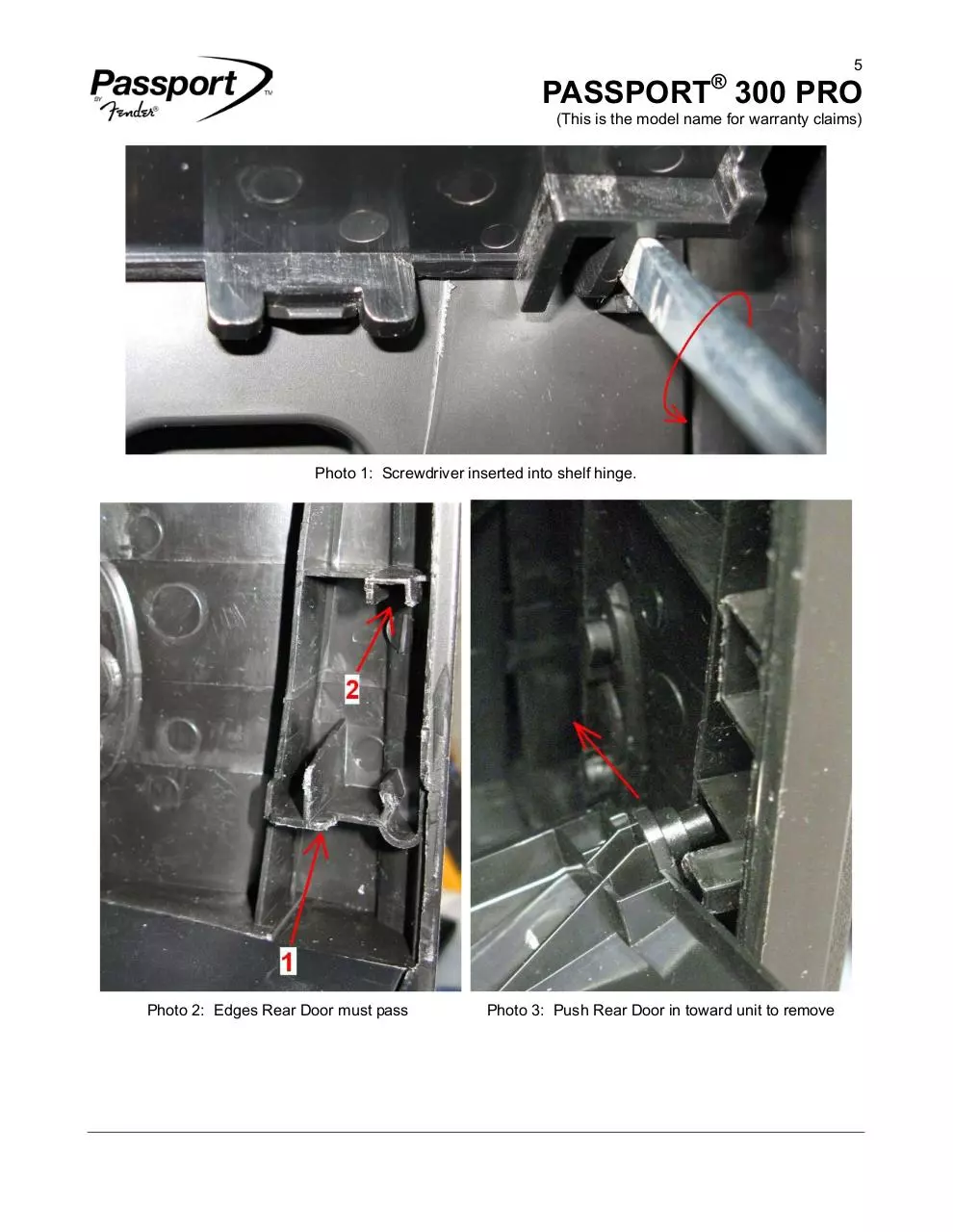
1. Shelf Removal – Open the Rear Panel Door.
Then, using a screwdriver or flat tool, insert the
screwdriver head into the slot at the right hinge
and twist the screwdriver (as shown below in
photo 1) and pull the door out; this should
release the shelf from the hinge. Do not push
too hard since the hinges are made of plastic.
Repeat this for the other shelf and both shelves
can be removed.
2. Rear Door Disassembly – Open the Rear
Panel Door. Pull the door up, releasing it from
its hinges on either side of the bottom of the
door. Now, notice the two inner edges noted in
photo 2. Tilt the Rear Door upward until the
bottom right edge of the door is able to clear
edge 1, and pull the bottom right side of the
Rear Door up past this edge until the right leg of
the door meets the edge (2) above it (see photo
3). Tilt the door back down, and push the door
into toward the unit such that the right edge of
the Rear Door clears this edge. The Rear Door
can now be removed. (Note: This is the first
step for disassembling other parts)
3. SMPS & AMP Module Disassembly –
Unscrew the six M3 screws on the rear panel,
then pull the SMPS/AMP module out of the
Passport enclosure. Unplug all connectors
before completely removing the SMPS/AMP
module. (Note: This is the second step for
disassembling other parts)
4. SMPS PCB & AMP PCB Disassembly –
Unscrew the two M9 nuts locking the speaker
output jacks on the rear panel. Unscrew the
eight M3 flat screws on the rear panel. Unplug
all connectors and remove the rear Panel.
Unscrew the six screws from the Cover A box
and remove Cover A. Unscrew the one M3 flat
screw from the Cover B box that is attached to
the AMP PCB bracket. Unscrew the eight M3
screws holding the SMPS PCB and remove the
Cover B box. Unplug the connectors between
the SMPS PCB and AMP PCB. Unscrew the
four M3 screws on the Bracket-AMP IC and
remove the bracket. Unscrew the two M3
screws on the bottom side of the SMPS PCB
that are holding the AMP PCB in place.
5. Front Panel Disassembly – Removing the
front panel is a two step process. Unscrew the
three M3 screws of the Partition Main board
that is being accessed from the back. Unplug
the connector, and then remove the Partition
Main board. Unscrew the eight M3 screws that
are holding the front panel in place. The front
panel can now be removed.
6. INPUT PCB Disassembly – Remove the
stereo out knob from the front. Remove the
eleven M9 nuts and washers from the input
jacks. Unscrew the eight XLR jack mounting
screws. Unscrew the three M3 screws from the
Input PCB. The Input PCB can now be
removed. (Note: This step must be performed
after step 4)
7. Mixer PCB Disassembly – Remove all 26
knobs from the front of the unit. Unscrew the
eleven M3 screws from the mixer PCB. The
Mixer PCB can now be removed. (Note: This
step must be performed after the step 5)
®
5
PASSPORT 300 PRO
(This is the model name for warranty claims)
Photo 1: Screwdriver inserted into shelf hinge.
Photo 2: Edges Rear Door must pass
Photo 3: Push Rear Door in toward unit to remove
®
6
PASSPORT 300 PRO
(This is the model name for warranty claims)
PCB EXCHANGE POLICY
Parts marked with a single asterisk (*) in the Parts
List are not field replaceable. If a failure due to one
of these components is detected, please contact
the FMIC Customer Service Department to order
the complete PCB Assembly.
CIRCUIT DESCRIPTION
This section provides concise information about new
or unusual circuitry designs incorporated into this
amplifier model. The purpose is to aid the service
technician by providing insight into the design areas
most likely to become obstacles in troubleshooting.
Information is focused for its effective use while
maintaining the security of Fender® proprietary
information wherever possible.
U502 (ICE2B365) is the PWM controller integration
switch MOSFET to drive Transformer T504, which
supplies +15/-15VDC, 8VDC, 12VDC, 24VDC,
+5VDC, +48VDC and switches on the PWM
controller U501 (KA3844B). U501 then alternately
switches Q501 and Q502 on and off according to
the load condition to drive transformer T501, which
supplies +40/-40VDC and +5/-5VDC voltage to the
Class-D amplifier PCB assembly.
The 300 PRO consists of the following modules.
1.
2.
3.
4.
The SMPS PCB Module
The Input PCB Module
The Mixer PCB Module
The Class-D Amplifier PCB Module
The SMPS PCB Module
The SMPS PCB Module uses SW501 to select
input AC mains voltages ranging from 100V ~ 120V
(50/60Hz) at the 115V AC mains setting, and 220V
~ 240V (50/60Hz) at the 230VAC mains setting. It
then provides the following output voltages to power
the 300 Pro for various functionalities.
1. +40/-40VDC for the class-D amplifier PCB
assembly
2. +5/-5VDC for the class-D amplifier PCB
assembly
3. +12VDC V_driver for the Class-D amplifier PCB
assembly
4. +15/-15VDC for the input PCB assembly
5. +24Vdc for The fan
6. +8VDC for the wireless microphone
7. +5VDC for the MCU and LED etc.
8. +48VDC for the microphone
The Input PCB Module
The input PCB provides a series of input and output
jacks as described below.
1. Channel 1-4 with XLR and ¼” TRS phone jacks
2. Channel 5-6 with 1/8“stereo and ¼” TRS phone
jacks.
3. ¼” TRS Pre-Amp Out / Power Amp In phone
jacks
4. 1/8” stereo output with volume control.
5. ¼” Subwoofer output.
Channel 1-4 also contain “PAD” switches which
provide 20dB of attenuation when being engaged.
Channel 5-6 can be used for both, mono as well as
stereo input sources. The input is a mono input
when only the L/Mono jack is being used. The XLR
jacks on channel 1-4 can provide +48VDC phantom
power when the phantom power switch is being
engaged. The signal from the XLR and ¼” phone
jacks are either amplified (Mic input by +40dB) or
buffered (Line input by 0dB) and then fed to the
Mixer PCB.
All signals that are coming from the mixer buss is
being fed through a limiter and then fed to the
amplifier.
®
7
PASSPORT 300 PRO
(This is the model name for warranty claims)
The Mixer PCB Module
The Mixer PCB module receives input signal from
channel 1-6. It provides the following control
functions for each channel.
1.
2.
3.
4.
5.
LEVEL VOLUME
EQ LOW
EQ HIGH
REVERB VOLUME.
INPUT SIGNAL PRESENT / CLIP INDICATOR.
The input signals from each channel along with the
reverb output are summed at U214. The summed
signal is going through a System EQ and a Master
Volume Control to the amplifier module via the Input
PCB. The output level is being shown on the LED
meter bar.
The AMP Module
The amplifier is a two-channel 150W per channel /
4 Ohm half-bridge Class-D audio power amplifier.
Its power supply is +/-40VDC.
The main features about the amplifier are as
follows:
Output Power: 150 W per channel into 4 Ohms at
1% THD+N at 1kHz.
Multiple Protection Features
-
Over-current protection (OCP),
Over-voltage protection (OVP),
Under-voltage protection (UVP),
DC-protection (DCP),
Over-temperature protection (OTP)
®
8
PASSPORT 300 PRO
(This is the model name for warranty claims)
.PARTS LIST:
AMP - PCB ASSEMBLY
QTY
PART #
DESCRIPTION
REFERENCE DESIGNATION
1
0079972000
*PCB ASSY, PWR AMP
Complete AMP PCB Assembly
3
REF
CC 25V 10U 10% 1206
C767, C768, C769
2
REF
CC 25V 22U 10% 1210
C735, C736
4
REF
CC 25V 3.3U 10% 1210
C747, C748, C749, C750
12
REF
CC 50V 0.1uF 10% 0805
C708, C709, C747A, C748A, C749A, C750A, C775, C7G1, C7G2,
C7HS1, C7HS2, CS1
4
REF
CC 50V 220pF 5% 0805
C702, C703, C706, C707
1
REF
CC 50V 0.22U 10% 0805
C777
4
REF
CC 50V 2.2U 10% 1206 X7R
C730, C731, C732, C770
2
REF
CC 50V 47pF 5% 0805 1.2x
C728, C729
2
REF
CC 50V 0.047U 10% 0805
C765, C766
2
REF
CC 100V 4700P 10% 0805
C759A, C760A
2
REF
CC 500V 150P 10% RLT 7X9
C755, C756
8
REF
CC 250V 1000P 5% 0805
C737, C738, C740, C742, C751, C752, C753, C754
6
REF
CC 250V 0.1U 10% X7R
C716, C717, C718, C719, C739, C741
2
REF
CM 400VDC 0.47U 5% RB
C759, C760
2
REF
CM 400V 0.1U 5% RL 18X14
C761, C762
2
REF
CT 16V 10uF 20% SM
C733, C734
1
REF
CE 16V 10uF 20% RL 4x7
C778
1
REF
CE 16V 100U 20% RLR 5x11
C774
2
REF
CE 16V 22UF 20% RL 4X7
C743, C744
4
REF
CE 16V 22U 20% RLR 4X7
C700, C701, C704, C705
4
REF
CE 50V 2200UF 20% RL
C720, C721, C722, C723
1
REF
PCB AMP D/S 94V0 VER03
AMP
2
REF
INDUCTOR 22UH +/-20%
L700, L701
2
REF
CHOKE-COMMON MODE 10A
CL700, CL701
1
REF
WAFER 4P P3.96 STRAIGHT
JB702
1
REF
CONNECTOR SOCKET 7P
JB703
2
0079947000
JACK, 1/4 INCH SPKR
CH700, CH701
1
REF
IC DUAL OP AMP NE5532D
U700
2
REF
IC GATE DRIVER IRS20957S
U703, U704
2
REF
IC ASIC TLC081 SO-8
U705, U706
2
REF
BRACKET-GROUNDING PCB
M702, M703
2
REF
BRACKET-MAIN
M700, M701
2
REF
RMF 1W 2K 5% ATS METAL O
R794, R795
2
REF
RMF 1W 47K 1% ATS
R783, R785
3
REF
RMG 1/10W 0R 1% 0805
R718, R724A, R725A
1
REF
RMG 1/10W 0R 5% 0805
R788
*
shaded
shaded + *
**
shaded + **
Non-serviceable part. Replace complete parent assembly. See PCB EXCHANGE POLICY section above.
Unique Fender® part. Order directly from the FMIC Parts Department.
Access to this part or assembly is controlled. Please contact the FMIC Customer Service Department.
Safety Requirement part. Replacement must match Safety Agency…–Value, if specified –Type, if specified –Approval Mark(s) if on part.
Both a unique Fender® part and a Safety Requirement part as defined above.
®
9
PASSPORT 300 PRO
(This is the model name for warranty claims)
.PARTS LIST:
AMP - PCB ASSEMBLY
QTY
PART #
2
REF
RMG 1/10W 10R 1% 0805
6
REF
RMG 1/10W 100R 1% 0805
R710, R712A, R713A, R745, R746, R766
9
REF
RMG 1/10W 1K 1% 0805
R719C, R723, R723B, R730, R732, R733, R734, R736, R737
7
REF
RMG 1/10W 10K 1% 0805
R706A, R707A, R755, R757, R759, R764, R765
6
REF
RMG 1/10W 100K 1% 0805
R700A, R701A, R711, R712, R719B, R763
3
REF
RMG 1/10W 1M 1% 0805
R700C, R700D, R721B
2
REF
RMG 1/10W 15K 1% 0805
R767, R768
1
REF
RMG 1/10W 18K 1% 0805
R721
1
REF
RMG 1/10W 2K 1% 0805
R719A
1
REF
RGM 1/10W 220R 1% 0805
R735
1
REF
RMG 1/10W 2.2K 1% 0805
R718A
2
REF
RMG 1/10W 2.4K 1% 0805
R743, R744
1
REF
RMG 1/10W 270R 1% 0805
R731
1
REF
RMG 1/10W 2.7K 1% 0805
R719
6
REF
RMG 1/10W 3.3K 1% 0805
R702A, R703A, R708A, R709A, R754A, R758A
1
REF
RMG 1/10W 33K 1% 0805
R703
2
REF
RMG 1/10W 39K 1% 0805
R781, R782
2
REF
RMG 1/10W 470R 1% 0805
R716A, R717A
1
REF
RMG 1/10W 4.7K 1% 0805
R721C
6
REF
RMG 1/10W 47K 1% 0805
R718B, R789, R790, R791, R792, R798
8
REF
RMG 1/10W 4.7R 1% 0805
R700B, R701B, R775, R776, R777, R778, R779, R780
9
REF
RMG 1/10W 5.1K 1% 0805
R700, R701, R705, R706, R707, R708, R709, R718C, R726
4
REF
RMG 1/10W 6.8K 1% 0805
R717, R729A, R748, R751
5
REF
RMG 1/10W 8.2K 1% 0805
R702, R702B, R721A, R749, R752
2
REF
RMG 1/8W 6.8K 5% 1206
R750, R753
4
REF
RMG 1/4W 22R 1% 1206
R771, R772, R773, R774
4
REF
RMG 1W 5.1R 5% 2512
R704A, R704B, R705A, R705B
2
REF
RWR 5W 10R 5% AL
R722A, R723A
15
REF
DIODE LL4148 SM
D700, D701, D702, D703, D718, D719, D723, D724, D725, D738, D739,
D740, D741, D742, D743
8
REF
DIODE ULTRA 200V ER1D
D710, D711, D712, D713, D714, D715, D716, D717
2
REF
DIODE SCHOTTKY 40V 1A
D708, D709
1
REF
DZ 1/2W 22VD RLZTE-1122D
Z705
1
REF
DZ 1/2W 3.3V SMD ROHM
Z701
1
REF
DZ 1/2W 47V 0805
Z706
4
REF
TR PNP MMBT5401 HFE: 50
Q712, Q715, Q717, Q718
4
REF
TR NPN MMBT5551 HFE: 80
Q706, Q707, Q710, Q714
6
REF
TR MMBT3904LT1G NPN
Q705, Q716, Q719, Q720, Q721, Q722
*
shaded
shaded + *
**
shaded + **
DESCRIPTION
REFERENCE DESIGNATION
R769, R770
Non-serviceable part. Replace complete parent assembly. See PCB EXCHANGE POLICY section above.
Unique Fender® part. Order directly from the FMIC Parts Department.
Access to this part or assembly is controlled. Please contact the FMIC Customer Service Department.
Safety Requirement part. Replacement must match Safety Agency…–Value, if specified –Type, if specified –Approval Mark(s) if on part.
Both a unique Fender® part and a Safety Requirement part as defined above.
Download Passport 300 Pro Service Manual NO DIAGRAMS
Passport 300 Pro Service Manual NO DIAGRAMS.pdf (PDF, 641.64 KB)
Download PDF
Share this file on social networks
Link to this page
Permanent link
Use the permanent link to the download page to share your document on Facebook, Twitter, LinkedIn, or directly with a contact by e-Mail, Messenger, Whatsapp, Line..
Short link
Use the short link to share your document on Twitter or by text message (SMS)
HTML Code
Copy the following HTML code to share your document on a Website or Blog
QR Code to this page

This file has been shared publicly by a user of PDF Archive.
Document ID: 0000319978.