CRV CR V Radio Connector Pins (PDF)
File information
Title: http://tor.in.honda.com/Rjanisis/pubs/sm/1/2/Contents/enu/61T0A
Author: Auto Enlightenment
This PDF 1.3 document has been generated by PrimoPDF http://www.primopdf.com / Nitro PDF PrimoPDF, and has been sent on pdf-archive.com on 18/12/2015 at 20:14, from IP address 66.115.x.x.
The current document download page has been viewed 7311 times.
File size: 367.75 KB (17 pages).
Privacy: public file

File preview
http://tor.in.honda.com/Rjanisis/pubs/sm/1/2/Contents/enu/61T0AD/GEN/SCT/SC/SYS/G000077_... 8/7/2012
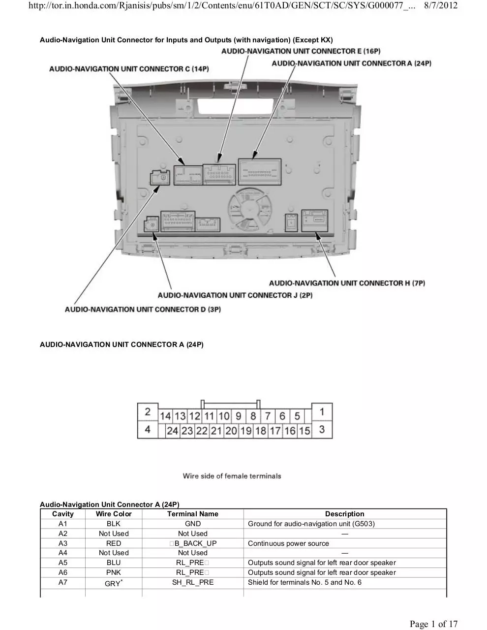
Audio-Navigation Unit Connector for Inputs and Outputs (with navigation) (Except KX)
AUDIO-NAVIGATION UNIT CONNECTOR A (24P)
Audio-Navigation Unit Connector A (24P)
Cavity
Wire Color
Terminal Name
A1
BLK
GND
A2
Not Used
Not Used
A3
RED
B_BACK_UP
A4
Not Used
Not Used
A5
BLU
RL_PRE
A6
PNK
RL_PRE
*
SH_RL_PRE
A7
GRY
Description
Ground for audio-navigation unit (G503)
―
Continuous power source
―
Outputs sound signal for left rear door speaker
Outputs sound signal for left rear door speaker
Shield for terminals No. 5 and No. 6
Page 1 of 17
http://tor.in.honda.com/Rjanisis/pubs/sm/1/2/Contents/enu/61T0AD/GEN/SCT/SC/SYS/G000077_... 8/7/2012
A8
A9
A10
A11
A12
A13
A14
A15
A16
A17
A18
A19
A20
A21
A22
A23
A24
GRY*
LT BLU
PUR
Not Used
GRN
LT BLU
Not Used
BRN
YEL
GRY*
GRY*
RED
GRN
RED
Not Used
GRN
PUR
SH_RR_PRE
RR_PRE
RR_PRE
Not Used
SCTY_RADIO_SW
K_LINE
Not Used
FL_PRE
FL_PRE
SH_FL_PRE
SH_FR_PRE
FR_PRE
FR_PRE
SWD B
Not Used
VSP
ACC
Shield for terminals No. 9 and No. 10
Outputs sound signal for right rear door speaker
Outputs sound signal for right rear door speaker
―
Security signal from MICU
Detects scan tool signal (serial data)
―
Outputs sound signal for left front speakers
Outputs sound signal for left front speakers
Shield for terminals No. 15 and No. 16
Shield for terminals No. 19 and No. 20
Outputs sound signal for right front speakers
Outputs sound signal for right front speakers
Outputs voltage for stereo amplifier switching ON/OFF
―
Detect vehicle speed pulse from PCM
Power source for accessories
*: The shielded wires have a heat-shrink tube insulating the outside of the wire. The color of the insulating tube, typically black or dark
gray, may not match the color of the wire shown on the circuit diagram.
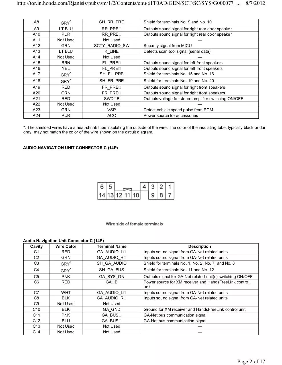
AUDIO-NAVIGATION UNIT CONNECTOR C (14P)
Audio-Navigation Unit Connector C (14P)
Cavity
Wire Color
Terminal Name
C1
RED
GA_AUDIO_L
C2
GRN
GA_AUDIO_R
SH_GA_AUDIO
C3
GRY*
C5
C6
GRY*
PNK
RED
C7
C8
C9
C10
C11
C12
C13
C14
WHT
BLK
Not Used
BLK
PNK
BLU
Not Used
Not Used
C4
Description
Inputs sound signal from GA-Net related units
Inputs sound signal from GA-Net related units
Shield for terminals No. 1, No. 2, No. 7, and No. 8
SH_GA_BUS
Shield for terminals No. 11 and No. 12
GA_SYS_ON
GA B
Outputs signal for GA-Net related unit(s) switching ON/OFF
Power source for XM receiver and HandsFreeLink control
unit
Inputs sound signal from GA-Net related units
Inputs sound signal from GA-Net related units
―
Ground for XM receiver and HandsFreeLink control unit
GA-Net bus communication signal
GA-Net bus communication signal
―
―
GA_AUDIO_L
GA_AUDIO_R
Not Used
GA_GND
GA_BUS
GA_BUS
Not Used
Not Used
Page 2 of 17
http://tor.in.honda.com/Rjanisis/pubs/sm/1/2/Contents/enu/61T0AD/GEN/SCT/SC/SYS/G000077_... 8/7/2012
*: The shielded wires have a heat-shrink tube insulating the outside of the wire. The color of the insulating tube, typically black or dark
gray, may not match the color of the wire shown on the circuit diagram.
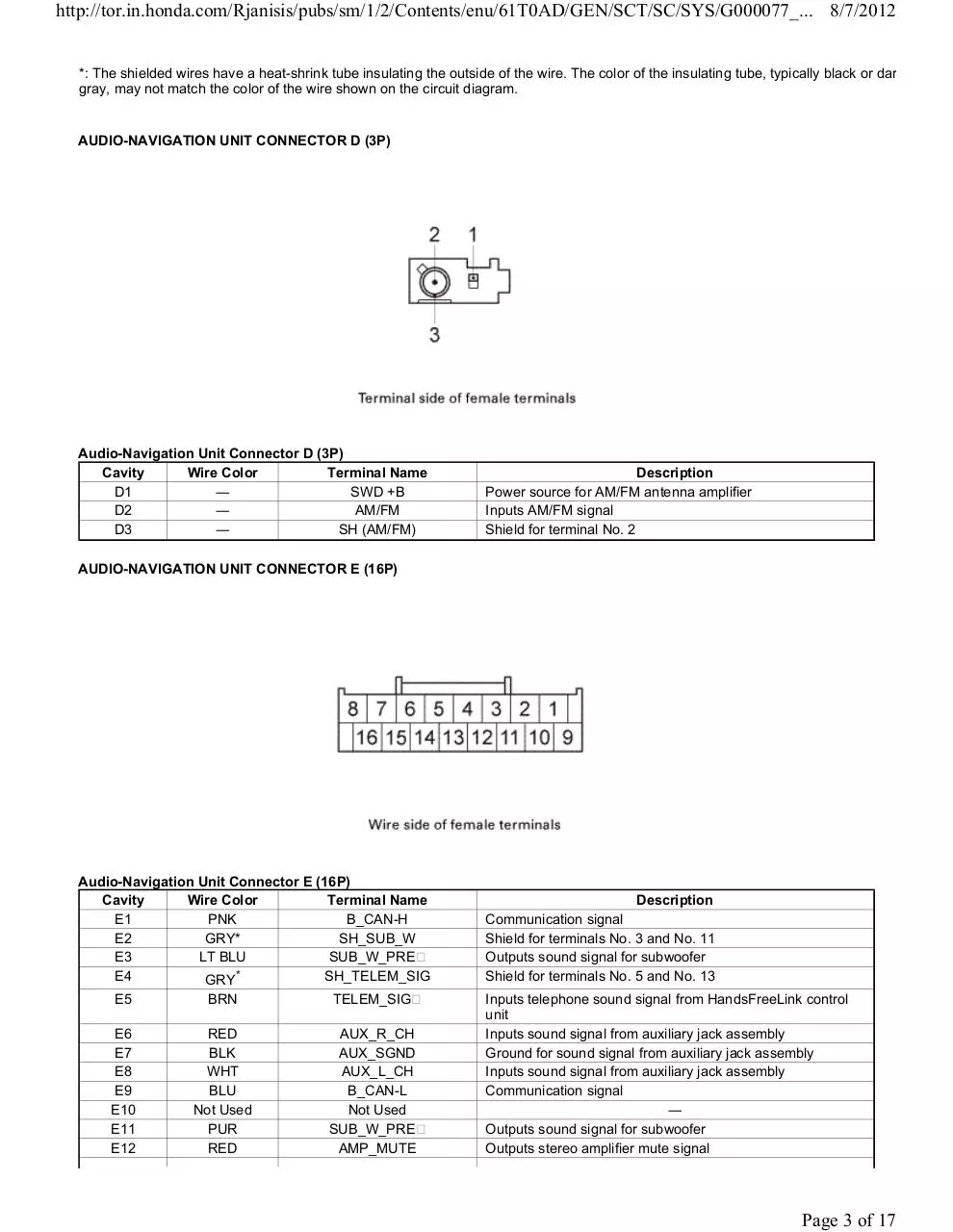
AUDIO-NAVIGATION UNIT CONNECTOR D (3P)
Audio-Navigation Unit Connector D (3P)
Cavity
Wire Color
Terminal Name
D1
―
SWD +B
D2
―
AM/FM
D3
―
SH (AM/FM)
Description
Power source for AM/FM antenna amplifier
Inputs AM/FM signal
Shield for terminal No. 2
AUDIO-NAVIGATION UNIT CONNECTOR E (16P)
Audio-Navigation Unit Connector E (16P)
Cavity
Wire Color
Terminal Name
E1
PNK
B_CAN-H
E2
GRY*
SH_SUB_W
E3
LT BLU
SUB_W_PRE
*
SH_TELEM_SIG
E4
GRY
E5
BRN
TELEM_SIG
E6
E7
E8
E9
E10
E11
E12
RED
BLK
WHT
BLU
Not Used
PUR
RED
AUX_R_CH
AUX_SGND
AUX_L_CH
B_CAN-L
Not Used
SUB_W_PRE
AMP_MUTE
Description
Communication signal
Shield for terminals No. 3 and No. 11
Outputs sound signal for subwoofer
Shield for terminals No. 5 and No. 13
Inputs telephone sound signal from HandsFreeLink control
unit
Inputs sound signal from auxiliary jack assembly
Ground for sound signal from auxiliary jack assembly
Inputs sound signal from auxiliary jack assembly
Communication signal
―
Outputs sound signal for subwoofer
Outputs stereo amplifier mute signal
Page 3 of 17
http://tor.in.honda.com/Rjanisis/pubs/sm/1/2/Contents/enu/61T0AD/GEN/SCT/SC/SYS/G000077_... 8/7/2012
E13
YEL
E14
GRY*
LT GRN
LT BLU
E15
E16
TELEM_SIG
SH_AUX
AUX_GND
AUX_DET
Inputs telephone sound signal from HandsFreeLink control
unit
Shield for terminals No. 6, No. 7, and No. 8
Ground for auxiliary jack assembly
Detects connection signal for auxiliary jack assembly
*: The shielded wires have a heat-shrink tube insulating the outside of the wire. The color of the insulating tube, typically black or dark
gray, may not match the color of the wire shown on the circuit diagram.
AUDIO-NAVIGATION UNIT CONNECTOR H (7P)
Audio-Navigation Unit Connector H (7P)
Cavity
Wire Color
Terminal Name
H1
―
USB GND
H2
―
USB_DATA
H3
―
USB_DATA
H4
―
USB_VBUS
H5
―
USB SH
H6
―
USB ADPT
H7
―
USB ON
Description
Ground for communication signal
Communication signal
Communication signal
Outputs power source for USB device
Shield for terminals No. 1, No. 2, No. 3, and No. 4
Ground for connection signal
Detects connection signal
*: The shielded wires have a heat-shrink tube insulating the outside of the wire. The color of the insulating tube, typically black or dark
gray, may not match the color of the wire shown on the circuit diagram.
AUDIO-NAVIGATION UNIT CONNECTOR J (2P) (USA models)
Audio-Navigation Unit Connector J (2P) (USA models)
Cavity
Wire Color
Terminal Name
Description
Page 4 of 17
http://tor.in.honda.com/Rjanisis/pubs/sm/1/2/Contents/enu/61T0AD/GEN/SCT/SC/SYS/G000077_... 8/7/2012
J1
J2
―
―
TMC RF IN
TMC RF SH
Inputs FM signal
Shield for terminal No. 1
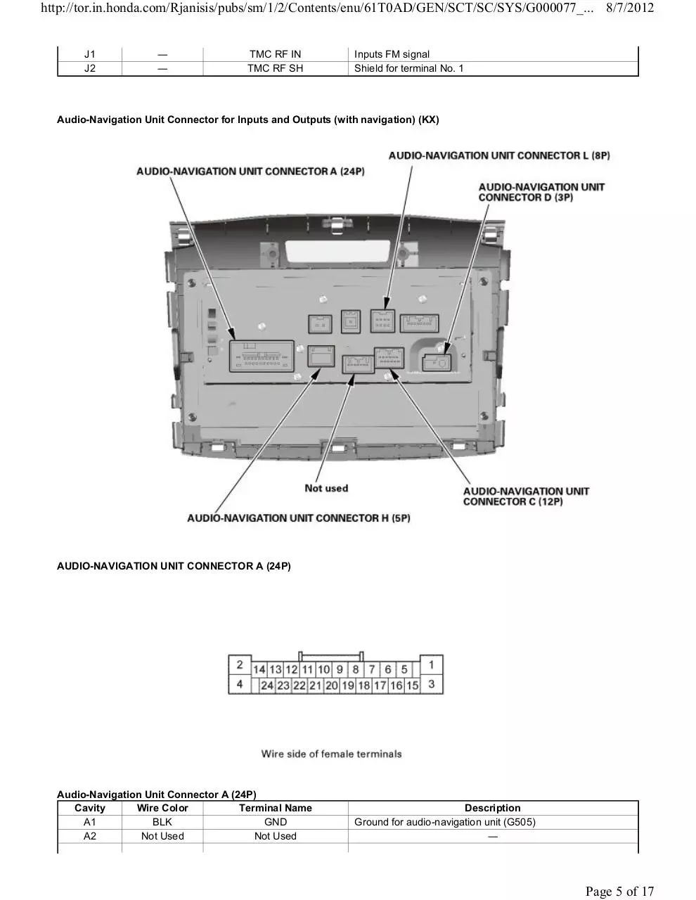
Audio-Navigation Unit Connector for Inputs and Outputs (with navigation) (KX)
AUDIO-NAVIGATION UNIT CONNECTOR A (24P)
Audio-Navigation Unit Connector A (24P)
Cavity
Wire Color
Terminal Name
A1
BLK
GND
A2
Not Used
Not Used
Description
Ground for audio-navigation unit (G505)
―
Page 5 of 17
http://tor.in.honda.com/Rjanisis/pubs/sm/1/2/Contents/enu/61T0AD/GEN/SCT/SC/SYS/G000077_... 8/7/2012
A3
A4
A5
A6
A7
A8
A9
A10
A11
A12
A13
A14
A15
A16
A17
A18
A19
A20
A21
A22
A23
A24
RED
GRY
BLU
PNK
Not Used
Not Used
BLU
ORN
Not Used
GRN
Not Used
Not Used
WHT
BLK
Not Used
Not Used
RED
GRN
Not Used
Not Used
Not Used
PUR
B_BACK_UP
ILLUMI
RL_SPKR
RL_SPKR
Not Used
Not Used
RR_SPKR
RR_SPKR
Not Used
SCTY_RADIO_SW
Not Used
Not Used
FL_SPKR
FL_SPKR
Not Used
Not Used
FR_SKPR
FR_SPKR
Not Used
Not Used
Not Used
ACC
Continuous power source
Power source for illumination
Outputs sound signal for left rear door speaker
Outputs sound signal for left rear door speaker
―
―
Outputs sound signal for right rear door speaker
Outputs sound signal for right rear door speaker
―
Security signal from MICU
―
―
Outputs sound signal for driver's door speakers
Outputs sound signal for driver's door speakers
―
―
Outputs sound signal for passenger's door speakers
Outputs sound signal for passenger's door speakers
―
―
―
Power source for accessories
AUDIO-NAVIGATION UNIT CONNECTOR C (12P)
Audio-Navigation Unit Connector C (12P)
Cavity
Wire Color
Terminal Name
C1
BLU
GA_BUS
C2
PNK
GA_BUS
C3
SH_GA_BUS
GRY*
C4
C5
C6
YEL
Not Used
PNK
HFT/NAVI_REMOTE_SW
Not Used
GA_SYS_ON
C7
C8
C9
C10
C11
C12
Not Used
Not Used
Not Used
Not Used
Not Used
Not Used
Not Used
Not Used
Not Used
Not Used
Not Used
Not Used
Description
GA-Net bus communication signal
GA-Net bus communication signal
Shield for terminals No. 1 and No. 2
Detects control signal from HFT switch
―
Outputs signal for multi-information display unit switching
ON/OFF
―
―
―
―
―
―
*: The shielded wires have a heat-shrink tube insulating the outside of the wire. The color of the insulating tube, typically black or dark
gray, may not match the color of the wire shown on the circuit diagram.
Page 6 of 17
http://tor.in.honda.com/Rjanisis/pubs/sm/1/2/Contents/enu/61T0AD/GEN/SCT/SC/SYS/G000077_... 8/7/2012
AUDIO-NAVIGATION UNIT CONNECTOR D (3P)
Audio-Navigation Unit Connector D (3P)
Cavity
Wire Color
Terminal Name
D1
―
SWD +B
D2
―
AM/FM
D3
―
SH (AM/FM)
Description
Power source for AM/FM antenna amplifier
Inputs AM/FM signal
Shield for terminal No. 2
AUDIO-NAVIGATION UNIT CONNECTOR H (5P)
Audio-Navigation Unit Connector H (5P)
Cavity
Wire Color
Terminal Name
H1
―
USB GND
H2
―
USB DATA
H3
―
USB DATA
H4
―
USB VBUS
H5
―
USB SH
Description
Ground for communication signal
Communication signal
Communication signal
Outputs power source for USB device
Shield for terminals No. 1, No.2, No.3, and No. 4
AUDIO-NAVIGATION UNIT CONNECTOR L (8P)
Page 7 of 17
http://tor.in.honda.com/Rjanisis/pubs/sm/1/2/Contents/enu/61T0AD/GEN/SCT/SC/SYS/G000077_... 8/7/2012
Audio-Navigation Unit Connector L (8P)
Cavity
Wire Color
Terminal Name
L1
BLK
AUX SGND
L2
WHT
AUX_L_CH
L3
RED
AUX_R_CH
L4
Not used
Not used
L5
LT BLU
AUX_DET
L6
Not used
Not used
*
AUX_GND
L7
GRY
L8
Not used
Description
Ground for sound signal from auxiliary jack assembly
Inputs sound signal from auxiliary jack assembly
Inputs sound signal from auxiliary jack assembly
―
Detects connection signal for auxiliary jack assembly
―
Ground for sound signal from auxiliary jack assembly
Not used
―
Audio Unit Connector for Inputs and Outputs (with stereo amplifier)
Page 8 of 17
http://tor.in.honda.com/Rjanisis/pubs/sm/1/2/Contents/enu/61T0AD/GEN/SCT/SC/SYS/G000077_... 8/7/2012
AUDIO UNIT CONNECTOR A (24P)
Audio Unit Connector A (24P)
Cavity
Wire Color
A1
BLK
A2
Not Used
A3
RED
A4
Not Used
A5
BLU
A6
PNK
A7
GRY*1
A8
Terminal Name
GND
Not Used
B_AUDIO
Not Used
RL_PRE
RL_PRE
SH_RL_PRE
SH_RR_PRE
Description
Ground for audio unit (G503)
―
Continuous power source
―
Outputs sound signal for left rear door speaker
Outputs sound signal for left rear door speaker
Shield for terminals No. 5 and No. 6
Shield for terminals No. 9 and No. 10
Page 9 of 17
Download CRV CR-V Radio Connector Pins
CRV CR-V Radio Connector Pins.pdf (PDF, 367.75 KB)
Download PDF
Share this file on social networks
Link to this page
Permanent link
Use the permanent link to the download page to share your document on Facebook, Twitter, LinkedIn, or directly with a contact by e-Mail, Messenger, Whatsapp, Line..
Short link
Use the short link to share your document on Twitter or by text message (SMS)
HTML Code
Copy the following HTML code to share your document on a Website or Blog
QR Code to this page

This file has been shared publicly by a user of PDF Archive.
Document ID: 0000325078.