HIOKI 3193 10 ENG (PDF)
File information
Title: POWER HiTESTER 3193-10
Author: HIOKI
This PDF 1.7 document has been generated by Adobe InDesign CS5.5_J (7.5.3) / Adobe PDF Library 9.9, and has been sent on pdf-archive.com on 24/12/2015 at 15:40, from IP address 5.18.x.x.
The current document download page has been viewed 951 times.
File size: 3.24 MB (8 pages).
Privacy: public file


File preview
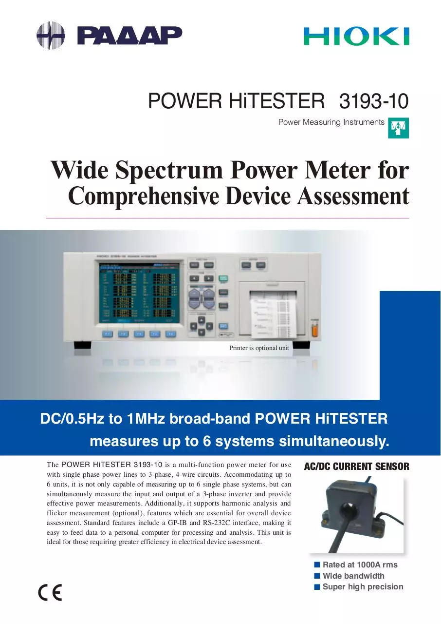
POWER HiTESTER 3193-10
Power Measuring Instruments
Wide Spectrum Power Meter for
Comprehensive Device Assessment
Printer is optional unit
DC/0.5Hz to 1MHz broad-band POWER HiTESTER
measures up to 6 systems simultaneously.
The POWER HiTESTER 3193-10 is a multi-function power meter for use
with single phase power lines to 3-phase, 4-wire circuits. Accommodating up to
6 units, it is not only capable of measuring up to 6 single phase systems, but can
simultaneously measure the input and output of a 3-phase inverter and provide
effective power measurements. Additionally, it supports harmonic analysis and
flicker measurement (optional), features which are essential for overall device
assessment. Standard features include a GP-IB and RS-232C interface, making it
easy to feed data to a personal computer for processing and analysis. This unit is
ideal for those requiring greater efficiency in electrical device assessment.
AC/DC CURRENT SENSOR
■ Rated at 1000A rms
■ Wide bandwidth
■ Super high precision
2
Broad coverage, high accuracy, and well-developed interface
Complete with functions that answer
all your power measurement needs.
Features
■ Wide range of measurement functions
Capable of measuring voltage, current, active /reactive /apparent
power, power factor, phase, frequency, and current, and of integrating
power according to polarity, the 3193-10 also provides wave peak and
efficiency measurements that are essential to device assessment.
■ Measure Motor Output
With the optional EXTERNAL SIGNAL INPUT UNIT 9603 , the
HiTESTER can take analog input in from torque and revolution
measurements and use that information to calculate motor output.
■ Measurement for Minute Stand-by Power also Available
(by special-order)
The 9600 and 9601 input units have 10-times improved
current sensitivity, and currents starting from the 20.000mA
range can be measured. (Please inquire for further information.)
■ High Visibility Color LCD
Featuring a wide viewing angle, the
color LCD displays a variety of items
simultaneously, making it ideal for
quickly grasping power usage on the
system being measured. Expanded
display is possible for any four
selected items.
Enlarged Indication
■ Harmonic and Flicker Analysis
Harmonic and flicker analysis are possible when using the optional
HARMONIC / FLICKER MEASUREMENTS UNIT 9605 .
■ High Basic Accuracy of ±0.2%
Measurements of even greater precision can be obtained using the
optional 9600 to 9602 input unit, which provides a basic accuracy of
±0.1% rdg,±0.1% f.s. (With the 9602, the accuracy of the clamp-on sensor is
a factor affecting total accuracy during power measurement.)
■ A Variety of Interfaces for Differing Needs
★ Connecting to a PC
The RS-232C and GP-IB interface, provided as
standard features, make it possible to connect the
power meter directly to a PC, allowing efficient
measurement, management and analysis of data.
★ Connecting to a Recorder
With 8 selectable D/A outputs and voltage,
current and power analog/monitor output
(current and voltage only) as standard features,
the HiTESTER allows recording of changes
and transient fluctuations in waveforms using a
recording unit.
★ Connecting to a Printer
Data can be output to the optional PRINTER UNIT 9604.
Print type
Paper width
Main functions
: Thermal line dot printing
: 72mm
: printing of items measured, hard copy output
of displayed screens, printout of meter settings,
printout of various times (such as interval
time, timer time, and realtime control time).
Printouts are performed either automatically,
upon input of an external control signal, or
synchronized with an integrator.
3
DC/0.5Hz to 1MHz broad-band POWER HiTESTER
measures up to 6 systems simultaneously.
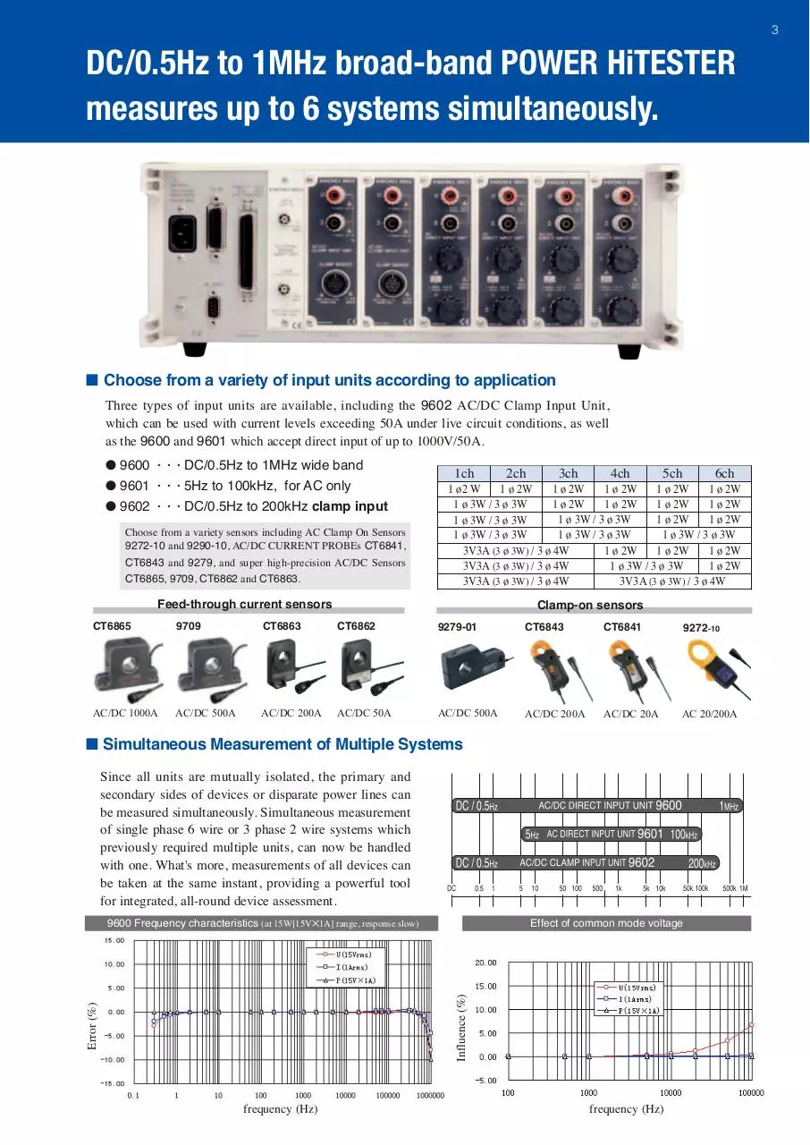
■ Choose from a variety of input units according to application
Three types of input units are available, including the 9602 AC/DC Clamp Input Unit,
which can be used with current levels exceeding 50A under live circuit conditions, as well
as the 9600 and 9601 which accept direct input of up to 1000V/50A.
● 9600 · · · DC/0.5Hz to 1MHz wide band
● 9601 · · · 5Hz to 100kHz, for AC only
● 9602 · · · DC/0.5Hz to 200kHz clamp input
Choose from a variety sensors including AC Clamp On Sensors
9272-10 and 9290-10, AC/DC CURRENT PROBEs CT6841,
CT6843 and 9279, and super high-precision AC/DC Sensors
CT6865, 9709, CT6862 and CT6863.
1ch
2ch
3ch
4ch
5ch
6ch
1 ø2 W
1 ø 2W
1 ø 2W
1 ø 2W
1 ø 2W
1 ø 2W
1 ø 3W / 3 ø 3W
1 ø 2W
1 ø 2W
1 ø 2W
1 ø 2W
1 ø 3W / 3 ø 3W
1 ø 2W
1 ø 2W
1 ø 3W / 3 ø 3W
1 ø 3W / 3 ø 3W
1 ø 3W / 3 ø 3W
1 ø 3W / 3 ø 3W
1 ø 2W
3V3A (3 ø 3W) / 3 ø 4W
1 ø 2W
1 ø 2W
3V3A (3 ø 3W) / 3 ø 4W
1 ø 3W / 3 ø 3W
1 ø 2W
3V3A (3 ø 3W) / 3 ø 4W
3V3A (3 ø 3W) / 3 ø 4W
Feed-through current sensors
Clamp-on sensors
CT6865
9709
CT6863
CT6862
9279-01
CT6843
CT6841
9272-10
AC/DC 1000A
AC/DC 500A
AC/DC 200A
AC/DC 50A
AC/DC 500A
AC/DC 200A
AC/DC 20A
AC 20/200A
■ Simultaneous Measurement of Multiple Systems
Since all units are mutually isolated, the primary and
secondary sides of devices or disparate power lines can
be measured simultaneously. Simultaneous measurement
of single phase 6 wire or 3 phase 2 wire systems which
previously required multiple units, can now be handled
with one. What's more, measurements of all devices can
be taken at the same instant, providing a powerful tool
for integrated, all-round device assessment.
Effect of common mode voltage
Error (%)
Influence (%)
9600 Frequency characteristics (at 15W[15V✕1A] range, response slow)
frequency (Hz)
frequency (Hz)
4
Measure all items at same point in time
The Power Analysis Station
■ Applications of 3193-10
Example of Application With Power Converter
Example of Assessment Trial of EV ( Electric Vehicle)
Measure mixed AC and DC components with a single unit.
Separate charge/generation
integration capability.
Measurement under live
circuit conditions.
(Clamp input)
● 3ch
U /I /P
Separate charge / generation
integration ±Wh
● 1, 2 ch
3 phase after DC/AC, AC U /I /P /Wh
● 1, 3, 4ch
AC U /I /P, Primary to secondary
efficiency
● 2, 5 ch
Monitoring of DC U /I /P after DC/AC
Even Supports Harmonic / Flicker analysis
when using the optional 9605 HARMONIC / FLICKER MEASUREMENTS UNIT .
Graph Display of Harmonics
Waveform Display
List Display of Harmonics
Vector Display of Harmonics
Voltage, current and power can be analyzed and displayed by bargraphs
of harmonic amplitude, content and phase angle.Voltage, current and
power can be displayed simultaneously for a single channel, or a single
parameter can be displayed simultaneously for each of three channels.
The harmonic list display shows the amplitude, pro-portion,
phase angle and distortion for each harmonic of voltage, current
and power. Displaying only proportion, or two parameters simultaneously, such as amplitude and phase angle, is selectable.
Flicker Measurement Display
Displays data during measurement in real-time. Display can also be
switched to D measurement and "Pst" value.
The waveform display shows one cycle of the voltage and current
waveforms. RMS and peak values can be displayed along with
voltage and current waveforms, or voltage and current waveforms
for up to three channels can be displayed at the same time.
The harmonic vector display shows the voltage, current and phase angle
for each harmonic, making clear the voltage-current phase relationship.
Monitor Display
The relative "d" voltage change ∆V/V and the instantaneous
flicker value "S(t)" can be displayed in a time series, so past
variations are clearly displayed.
5
9605 Specifications
(optional)
Installation
: Installs in the 3193-10 main unit
Measurement lines : Single-phase 2- and 3-wire, three-phase 4-wire
No. of channels : Up to 3 channels within channels 1 to 6, depending
on 3193-10 wiring mode
Output functions : RS-232C, GP-IB, printer
● Harmonic Waveform Analysis Functions
Measurement range : Fundamental frequency: 1 to 440 Hz
PLL system (5 to 440 Hz), external clock system (1 to 5 Hz)
Orders analyzed : Up to 50th harmonic (with 1 to 250 Hz fundamental)
Window width : 16 cycles (for 40 to 70 Hz fundamental)
Windowing type : Rectangular tiling (no gap between or overlap of windows)
Amount of data analyzed : 512 points (for 40 to 70 Hz fundamental)
Crest factor
: Up to 4 (current), and up to 3 (voltage)
Measurement items : Harmonic level, percentage and phase angle of each order
of harmonic wave for each of voltage, current and power.
Total up to 50th harmonic (of 40 to 70 Hz fundamental) for
voltage, current and power. Total harmonic distortion for
voltage and current (THD-F and THD-R)
Measurement of voltage, current, active power, peak voltage
and peak current values of the fundamental
: Every 1 window (except during communications with other devices)
Update rate
Screen displays : List, graph, vector and waveform
: Harmonic levels; at 45 to 66 Hz
Accuracy*
Voltage/current: ±0.5%rdg.±0.05% f.s.
Active power: ±1.0%rdg.±0.1% f.s.
For 45 to 66-Hz fundamental, effective input is 0.1 to 110%
of range
● Flicker Measurement Function
Measurement range : Fundamental frequency; 45 to 66 Hz, PLL synchronization system
Analysis items : dc (relative constant voltage change), d max (max. relative constant
voltage change), d(t)500ms (relative voltage change per time), P0.1/
P1s/ P3s/ P10s and 30s (cumulative probability), Pst (short-term flicker
value), Plt (long-term flicker value)
Screen displays : Measured value, CPF, Pst list, Monitor
Accuracy*
: RMS voltage ±0.5%rdg. ±0.05%f.s. (45Hz~66Hz)
* The reading accuracy of the input unit must combined with the analysis accuracy shown above. When
used with a clamp sensor, accuracy and frequency characteristics of the clamp must be added to the
analysis accuracy above.
Other Analysis Functions
Integration According to Polarity
Peak Measurements Function
Positive, negative, and total
current and power can be
integrated simultaneously for
all channels. This makes it
possible to grasp the income
and outflow of power at a
glance.
Voltage and current wave peaks
can be measured. The Peak
Hold function can be used to
find peak values and effective
maximums for motor rush
current waves.
Analog and D/A Output
Analog (voltage, current,
and effective power) and D/
A outputs (any selected eight
items) are output as a 5V range
full scale value. (Except for the
1000V range), 100ms response
time can be obtained by using
the FAST setting.
peak
value
Wave Monitor Output
With the voltage and current
ranges, waveforms are output
as 1V full scale values,
allowing waveforms to be
monitored using devices such
as recorders or synchroscopes.
Input wave
60Hz, sinwave
Active power
Analog output
Input wave
50kHz
Pulse
Voltage
Monitor Output
current
Monitor Output
Active power
D/A output
20µs
100ms
● 3 Types of Averaging Functions
Select from time average, moving average and exponential average.
● 3ch Frequency Measurement Function
With the frequency ranges, LPF and HPF can be used in combination, allowing
measurement of fundamental waveforms and carrier waveforms of inverters.
● Efficiency Calculation Function
Three efficiency calculations can be obtained simultaneously from measured voltage values.
● 3 Types of Built-in Low Pass Filters
Selectable cutoff frequencies (500/5k/300kHz) allow extraction of the
frequency component of fundamental inverter waveforms and provide
data compatibility with previous instruments.
● Choose from Three Types of Calculation Algorithms
Three selectable algorithms are provided for calculating apparent power
and reactive power, providing compatibility with previous devices
Multi-Channel Recorders
MEMORY HiCORDER MR8847-01/02/03
The Ideal Recorder for Field Use, Easy
Portability and Sturdy Construction
● 20M-Sampling/s
● Max. 16 ch + logic 16 ch
● 32M to 256M-Word Memory (2ch)
MEMORY HiCORDER MR8875
Smart Design - Smart Engineering
● 500k-Sampling/s
● Max. 16ch+Logic 8ch
● Memory 8M-word by each input
unit, total 32M-words
6
■ Optional Input Unit Specifications
Customized versions of Models 9600 and 9601 are also available for stand-by power
measurement with 10-times improved sensitivity for current ranges. Please ask for detailed specs.
AC/DC DIRECT INPUT UNIT 9600
Voltage
Current
Active power
Measurement
range
Max.operating input (55Hz)
Crest factor
Input resistance
Accuracy
DC
0.5
1
10
45
6.0000/15.000/30.000/
200.00/500.00mA/
Depends on
6.0000/15.000/30.000/
60.000/150.00/300.00/ 1. 0000/2.0000/5.0000/ combination of voltage 60.000/150.00/300.00/
600.00V/1.0000 kV 10.000/20.000/50.000 A
and current ranges
600.00V
1000Vrms/1500 V peak
2MΩ±5%
±0.1%rdg.±0.2%f.s.
10 k to 50kHz
(Depends on clamp-on sensor)
Lower of either (measured range ✕ 6)/ measured value or
maximum permissible rated peak/measured value
1mΩ max.
±0.1%rdg.±0.2%f.s.
to 45Hz
66Hz to 10kHz
650Vrms/850Vpeak
500.00mA to 1000.0A
Depends on
(Depends on clamp-on combination of voltage
sensor)
and current ranges
2MΩ±5%
200kΩ±5%
(Accuracy assured at 23˚C±5˚C (73˚F ±9˚F) at 80% R.H., power factor = 1, sine wave input, in-phase voltage 0, after DMAG)
±0.5%rdg.±0.5%f.s.
to 66Hz
65Arms/100 A peak
Lower of either (measured range ✕ 6) / measured value
or maximum permissible rated peak / measured value
to 1Hz
to 10Hz
AC/DC CLAMP INPUT UNIT 9602
Voltage
Current
Active power
±0.2%rdg.±0.2%f.s.
±0.1%rdg.±0.1%f.s.
±0.1%rdg.±0.2%f.s.
±0.3%rdg.±0.3%f.s.
←
←
←
←
←
←
←
←
←
←
←
←
←
←
±0.1%rdg.±0.2%f.s.
←
←
←
←
←
←
←
←
←
←
←
←
±0.5%rdg.±0.5%f.s.
←
←
±0.5%rdg.±0.5%f.s.
←
±0.3%rdg.±0.5%f.s.
±5%f.s. ±1.0%rdg.
±1.5%f.s. ±10.0%f.s. ±15%f.s.(up to 200kHz)
←
±30%f.s.(up to 200kHz)
±0.5%rdg.±0.5%f.s.
±0.2%rdg.±0.2%f.s.
±0.1%rdg.±0.2%f.s.
±0.1%rdg.±0.1%f.s.
±0.1%rdg.±0.2%f.s.
Less than 5 A Greater than 5 A Less than 5 A Greater than 5 A
50 k to 100kHz
±0.5%rdg.±0.5%f.s.
±0.5%rdg.
±0.5%rdg.
±0.5%f.s. ±2.5%f.s. ±0.5%f.s. ±5.0%f.s.
100k to 300kHz
±0.5%rdg.±0.5%f.s.
±0.5%rdg.
±0.5%f.s.
300k to 400kHz
±1.5%rdg.±0.5%f.s.
±1.0%rdg.
±0.5%f.s.
±1.0%rdg.
±2.5%f.s.
400k to 500kHz
±2.0%rdg.±1.0%f.s.
±2.0%rdg.
±2.5%f.s.
500k to 700kHz
±10.0%f.s.
±2.0%rdg.
±1.0%f.s.
±15.0%f.s.
9272-10
±30.0%f.s.
AC DIRECT INPUT UNIT 9601
Voltage
Current
Active power
Measurement
range
Max.operating input (55Hz)
Crest factor
Input resistance
5
65Arms/100 A peak
Assured Accuracy Range for Input Frequency of the 9600
9601 and 9602 each have assured ranges for input frequency.
Lower of either (measured range ✕ 6) / measured value
or maximum permissible rated peak / measured value
2MΩ±5%
1mΩ max.
(Accuracy assured at 23˚C ±5˚C(73˚F ±9˚F) at 80% R.H., power factor = 1, sine wave input, in-phase voltage 0)
±2.5%f.s.
to 10Hz
10 to 20Hz
20 to 45Hz
45 to 66Hz
66Hz to 5kHz
5k to 10kHz
←
←
←
←
←
←
±0.1%rdg.±0.1%f.s.
←
←
←
←
±0.2%rdg.±0.4%f.s.
←
←
±1.0%f.s.
←
←
±2.5%f.s.
←
←
←
←
←
±1.0%f.s.
±0.1%rdg.±0.2%f.s.
±0.1%rdg.±0.2%f.s.
10k to 20kHz
20k to 50kHz
50k to 100kHz
±10.0%f.s.
Input current (A)
Accuracy
200.00/500.00mA/
Depends on
60.000/150.00/300.00/6
1. 0000/2.0000/5.0000/ combination of voltage
00.00V/1.0000 kV
10.000/20.000/50.000 A
and current ranges
1000Vrms/1500 V peak
CT6841/CT6843 CT6865/9709
With the 9602, the accuracy of the clamp-on sensor is a factor affecting
total accuracy during current measurement, as are phase and frequency
characteristics. See page 8 for details on the clamp-on sensor specifications.
±15.0%f.s.
±15.0%f.s.
CT6862
CT6863
9279-01
Input voltage (V)
700k to 1 MHz
±10.0%f.s.
■ Compatible Clamp
(Optional)
Frequency (Hz)
Note 1: Assured accuracy ranges for different response settings are as follows: FAST (0.1 sec) to DC and greater than 50 Hz, MID (0.8 sec) to DC and greater than 10 Hz,
SLOW (5.0 sec) to DC or greater than 0.5 Hz
Note 2: Assured accuracy ranges for combined mode measurement are 10 Hz or greater for the AC mode, and DC only for the AC+DC mode or DC mode.
■ Calculation algorithm
S
U
M
1ø2W
3ø3W
(3V3A)
(Indicated only for single phase, 2 wire and 3 phase, 3 wire (3V3A).Two additional calculation algorithms can be selected for apparent/reactive power)
Voltage
U1
U1·2·3=
U1+ U2+ U3
3
Current
I1
I1·2·3=
I1+ I2+ I3
3
Active power
P1
P1·2·3 =P1+P2
Apparent power Reactive power Power factor
λ 1 =s1 P1/S1
S1 =U1✕I1
P1·2·3
λ 1·2·3 = su
S1·2 ·3
Phase
ø1 =s1 cos -1 λ 1
ø1·2·3=su cos -1 λ 1·2·3
Note 1: The above calculation algorithm is for a single phase, 2 wire input to ch 1, and 3 phase, 3 wire input to ch 1/2/3 (3 voltage, 3 current).
Note 2: The "s" before each power factor or phase operation indicates the lead or lag of current phase in relation to voltage. The "-" sign means current phase leads voltage
and when there is no symbol, it lags. "su" is "-" when the sum of reactive power is negative and "+" (but unsigned) when it is positive.
7
■ Basic specifications
Measurement line : Single phase 2 wire, single phase 3 wire, 3 phase 3 wire
(3V3A is possible), 3 phase 4 wire
Measurement item : When using 9600, 9601, 9602 (optional)
Voltage, current, voltage/current peak, effective/reactive/apparent power,
power factor, phase, frequency, current/power integration, load rate, efficiency.
When using the 9603 (optional)
Voltage, torque, r/min, frequency, motor output.
When using the 9605 (optional)
Harmonic, waveform, voltage fluctuation / flicker measurement function.
Display indication range : At the lowest range in the DC mode of Models 9600 & 9602: 0.2% to 130%
At the lowest range in the AC+DC mode of Models 9600 & 9602: 0.5% to 130%
At the 200mA range of Model 9601: 0.5% to 130%
At 0.1% to 130% of all other ranges.
All range is zero suppressed at less than lower % value.
Valid input range for voltage, current, and power is 0.5% to 110%
: 6.4 inch TFT color LCD (640 × 480 dot)
Display
Display resolution : 99999 count (except with integration), 9999999 count (with integration)
Rectification method : Switchable between RMS (true root mean square value) and MEAN
(average rectified RMS indication). When combined mode DC is
selected, its not possible to switch between them.
Display update rate : 8 times/sec.
: DC, AC + DC, AC (AC only when used in combination
Combined mode
with 9601 or 9602 + AC clamp-on sensor)
Analog response time : FAST (0.1 sec.), MID (0.8 sec.), SLOW (5.0 sec.)
(Time required for stabilization to within ±1% when input is changed
from 0% to 90%, or 100% to 10% of range.)
Low pass filter : OFF / 500Hz / 5kHz / 300kHz (-3dB) For 9601, 5k
/ 300kHz not available.
Polarity detection regulation filter : OFF / 200Hz (-3dB)
Analog output : Voltage / current / active power
DC ±5V f.s (1000V range is DC ±3.333 V f.s.)
Monitor output : Voltage / current: 1Vrms f.s. (1000V range is 0.6667 Vrms f.s.)
[Wave peak measurement]
Measurement items : Select either voltage or current for each unit (Shows absolute value of max.)
Effective Input Range : Effective value of sine wave is within effective input permissible in the range
[Motor output (Pm) measured]
Measurement method
Effective when 9603 ch A is torque (any of N/ m, mN/m, kN/m, kgf/m,
kgf/cm), and ch B is r/m
Display indication range : 0.1% to 130% of 9603 voltage range (polarity not indicated)
Calculation algorithm : Set to required format
[Efficiency measurement]
Calculable factors : Maximum of 3 formats
Calculated items : P for each input unit, Pm when combined with 9603
(Items measured with 9605 not allowed)
[D/A output]
Number of channels
Output impedance
Output items
Output voltage
Output update rate
[Interface]
GP-IB
RS-232C
:
:
:
:
:
8ch (12 bit D/A converter polarity + 11bit)
100Ω±5%
Outputs 8 arbitrarily selected items
DC±5V/f.s.
16 times/sec
: Conforms to IEEE-488.1 1987, with reference to IEEE-488.2 1987
: Start-stop synchronous, with baud rate of 2400 or 9600 bits/sec
[External Control]
Functions
: Integration start / stop control, Integration data reset, External
A/D (For display update when power meter display is in hold mode),
Manual print control
: From 0 / 5V logic signal or short//open contact signal
[Voltage/ Current/ Active power measurement]
Control signal level
Measurement range : See Page 5 specifications for individual input units
[Other functions]
[Integration measurement]
Number of measurements : 64 times/sec
Measurement range : 0 to±9999999 TAh / TWh (integration time up to 10,000 hours)
[Power factor/ Phase angle measurement]
Measurement range
: -1.0000 (lead) to 0.0000 to 1.0000 (lag)
-180˚(lead) to 0.00˚to 180.00˚(lag)
[Frequency measurement]
Number of channels : Max. 3ch (selection of voltage or current for arbitrary channel)
Effective input range : 0.5 Hz to 2 MHz
Measurement range : Auto / 50Hz/ 500Hz / 50 kHz / 2 MHz
9603 (optional) external input unit required
: Digital calculation from measured voltage or pulse signal
: PT/CT ratio Set range 0.0001 to 99999
: Time average (set interval time, timer time, and average of
realtime control time)
Moving average (number of samples: 8/16/32/64)
Exponential average (attenuation factor: 8/16/32/64)
Multilingual display : Japanese/English screen display switching
Set time (all types) : Interval control time (10 sec to 100 hours) in 10 sec increments
Scaling
Averaging
(When used in combination with printer, auto select increments)
Timer control time (1 min to 10000 hours) in 1 minute increments
Realtime control time, 1 minute increments
[Harmonic / Flicker measurement]
9605 (optional) required
Measurement item : See Page 4 specifications for 9605
■ Measurement accuracy (Accuracy guaranteed for 6 months, Post-adjustment accuracy guaranteed for 6 months)
V, A, W
Apparent / reactive
power
Integration
Power factor
Phase angle
Frequency
Wave peak
: Per accuracy table on page 5
: ±1 dgt. with respect to calculation from measured value (U, I, P)
sum value is max. ±3dgt.
: ±1dgt with respect to values calculated from measurements ( I, P)
: Max. ±3dgt with respect to values calculated from measurements (U, I, P)
: Max. ±3dgt with respect to values calculated from measurements (U, I, P)
: ±0.1% rdg. ±1 dgt. (0˚C to 40˚C(32˚F to 104˚F), for sine wave
input between 10% to 130% of U/I range)
: ±1% (at 0.5Hz to 1kHz), ±2% (at 1kHz to 10kHz), ±10%
(at 10kHz to 100kHz)
■ General Specifications
Location for use : Indoors, altitude to 2000 m, Pollution level 2
Ambient use humidity : Power meter, 0˚Cto 40˚C (32˚F to104˚F), rh below 80%(no condensation)
When using printer, 5˚C to 40˚C (41˚F to 104˚F), rh below 80%
Ambient storage humidity : -10˚C to 50˚C (14˚F to 122˚F), rh below 80% and no condensation
Maximum rated voltage to earth : Using with the 9600 and 9601
Voltage input terminal, Current input terminal
600 V measurement category III (expected transient overvoltage: 6000 V)
1000 V measurement category II (expected transient overvoltage: 6000 V)
Using with the 9602
Withstand voltage
(50/60 Hz, 1 minute)
Voltage input terminal
600 V measurement category III (expected transient overvoltage: 6000 V)
: AC5.55kV between U/I terminal and unit case, between U/I
terminal and power supply plug (for 9600 and 9601), between U
terminal and clamp input terminal, between U terminal and unit
case, between U input terminal and power supply plug (for 9602)
Motor output
Efficiency
: ±1dgt for calculations of each measured value
: Max. ±7 dgt with respect to values calculated from measure-
Thermal coefficient
Effect of in-phase
voltage
Effect of power factor
Actual time
D/A output
Analog output
Monitor output
: Within ±0.03% f.s/ ˚C
: Within ±0.05% f.s
ments of items substituted into algorithm
:
:
:
:
:
(1000 Vrms, 50/60Hz, between shorted voltage input terminals and case)
±0.15% f.s (power factor = 0)
±25ppm ±1dgt. (0 to 40˚C (73˚F to 41˚F))
Display accuracy - ±0.2% f.s
Display accuracy - ±0.2% f.s
Display accuracy - ±0.2% f.s (less than 100kHz)
Display accuracy - ±3dB (100k to 1MHz)
: Safety
EN61010
: EMC
EN61326
EN61000-3-2
EN61000-3-3
: AC100V/120V/200V/230V (switched automatically), 50/60Hz
Power supply
Maximum rated power : 150VA max.
Dimensions, mass : Approx 430 W ✕150 H ✕ 370 D mm, Approx13 kg
Certifications
Accessories
(Approx 16.93″(W ) 5.91″ (H)14.57″ (D), Approx 458.6 oz.)
(in configuration including 9600 5 6ch, 9603, 9604)
(Not including projections such as terminals, feet, and handles)
: Power cord 1, ground adapter (3P to 2P) 1,
connector 1
■ Current Sensors(Optional) Specifications
To use the Clamp-On sensor, be sure to order the factory option 9602 AC/DC Clamp Input Unit.
AC Clamp-on Conversion Adapter
Sensor
for AC only
AC/DC Current Sensors
Feed-through current sensors
CT6865 *
Model
9709 *
CT6863 * CT6862 *
Clamp-on sensors
9279-01
CT6843
9272-10 *
CT6841
Physical
appearance
CT
9290-10
CT ratio 10:1
For 9272-10 only
1000A
500A
200A
50A
500A
200A
20A
200A/20A
1500A
Primary current rating
Measurable conductor diameter φ36mm (1.42in) φ36mm (1.42in) φ24mm (0.94in) φ24mm (0.94in) φ40mm (1.57in) φ20mm (0.79in) φ20mm (0.79in) φ46mm (1.81in) φ55mm (2.17in)
Warming up for at
least 10 minutes:
Accuracy
45 to 66Hz
23˚C±3˚C (73˚F±5.4˚F)
Frequency
characteristics
(vibration amplitude, phase)
(deviation from the basic accuracy)
others
±0.05%rdg. ±0.05%rdg. ±0.05%rdg.
±0.01%f.s. ±0.01%f.s.
±0.01%f.s.
(vibration amplitude) (vibration amplitude)
(vibration amplitude)
After degaussing
and warming up for
at least 30 minutes:
±0.5%rdg.
±0.05%f.s.
(vibration amplitude)
±0.3%rdg. ±0.01%f.s.
(vibration amplitude)
±0.1˚max.
(phase, DC not specificied)
±0.2˚max.(phase, ±0.2˚max.(phase,
±0.2˚max.
±0.2˚max.
±0.2˚max.
±0.2˚max.(phase,
DC not specificied) DC not specificied) (phase, DC not specificied)
(phase)
(phase)
DC not specificied)
DC to 16Hz DC to 45Hz DC to 16Hz: DC to 16Hz DC to 1kHz DC to 500Hz DC to 500Hz 1Hz to 5kHz
: ±0.1%max. : ±0.2%max. : ±0.1%max. : ±0.1%max. : ±1.0%max. : ±0.3%max. : ±0.3%max.
: ±2.0%max.
To 5kHz
To 10kHz
To 100kHz
To 100kHz
To 10kHz
To 10kHz
To 10kHz
To 10kHz
20Hz to 5kHz
: ±5.0%max. : ±2.0%max. : ±2.0%max. : ±5.0%max. : ±2.5%max. : ±1.5%max. : ±1.5%max.
: ±2.5%max. : ±2.0%max
To 20kHz
To 100kHz
To 500kHz
To 1MHz
To 20kHz
To 500kHz
To 1MHz
To 100kHz
: ±30%max : ±30%max. : ±30%max. : ±30%max. : ±5.0%max. : ±30%max. : ±30%max.
: ±30%max.
80mm(3.15 in)
×20mm(0.79in) busbar
Set CT ratio : 2
*For further details, please refer to the individual product catalog for the instrument.
Ordering information
POWER HiTESTER
Order Code:
±0.3%rdg.
±1.5%rdg.
±0.01%f.s.
(vibration amplitude) (vibration amplitude)
3193-10
(main unit only)
Note: Main unit 3193-10 cannot operate alone - please purchase an input unit Model 9600 to 9605
for factory installation prior to shipment. All subsequent input unit replacements or expansions
must be conducted at HIOKI for an additional service charge.
(
) : 9600, 9601, 9602 can be selected.
Pattern A
Pattern B
Pattern C
Pattern D
Pattern E
Pattern F
Pattern G
1ch
2ch
3ch
4ch
5ch
6ch
1 ø 2W (
) 1 ø 2W (
) 1 ø 2W (
) 1 ø 2W (
) 1 ø 2W (
) 1 ø 2W (
)
1 ø 3W / 3 ø 3W (
×2 ) 1 ø 2W (
) 1 ø 2W (
) 1 ø 2W (
) 1 ø 2W (
)
1 ø 3W / 3 ø 3W (
×2 ) 1 ø 3W / 3 ø 3W (
×2 ) 1 ø 2W (
) 1 ø 2W (
)
1 ø 3W / 3 ø 3W (
×2 ) 1 ø 3W / 3 ø 3W (
×2 ) 1 ø 3W / 3 ø 3W (
×2 )
3V3A (3 ø 3W) / 3 ø 4W (
×3 ) 1 ø 2W (
) 1 ø 2W (
) 1 ø 2W (
)
3V3A (3 ø 3W) / 3 ø 4W (
×3 ) 1 ø 3W / 3 ø 3W (
×2 ) 1 ø 2W (
)
3V3A (3 ø 3W) / 3 ø 4W (
×3 )
3V3A (3 ø 3W) / 3 ø 4W (
×3 )
Options that can be installed at the factory
● Use the same input unit for a particular
measurement line.
● Install units in succession starting
from channel 1.
● For the 9603 only one unit can be
installed.
● When the 9602 is selected, use an
optional clamp-on sensor.
Options
(specify at time of order)
AC/DC DIRECT INPUT UNIT 9600
AC DIRECT INPUT UNIT 9601
AC/DC CLAMP INPUT UNIT 9602
EXTERNAL SIGNAL INPUT UNIT 9603
PRINTER UNIT 9604 * Not CE marked
HARMONIC / FLICKER MEASUREMENTS UNIT 9605
Notes on input unit selection
* Not CE marked
*Voltage cables are not supplied. Also, please contact your HIOKI
distributor for clip type leads or other special needs.
AC/DC CURRENT SENSOR CT6865 (1000A AC/DC)
AC/DC CURRENT SENSOR 9709 (500A AC/DC)
AC/DC CURRENT SENSOR CT6863 (200A AC/DC)
AC/DC CURRENT SENSOR CT6862 (50A AC/DC)
UNIVERSAL CLAMP ON CT 9279-01 (500A AC/DC)
AC/DC CURRENT PROBE CT6843 (200A AC/DC)
AC/DC CURRENT PROBE CT6841 (20A AC/DC)
CLAMP ON SENSOR 9272-10 (20/200A AC)
CLAMP ON ADAPTER 9290-10 (1500A AC, ratio10 :1)
VOLTAGE CORD L9438-50 (1 each red and black, approx 3m)
RECORDING PAPER 9232 (10 m, 10 roll, For 9604)
Note: Company names and Product names appearing in this catalog are trademarks or registered trademarks of various companies.
HIOKI (Shanghai) SALES & TRADING CO., LTD.
TEL +86-21-63910090 FAX +86-21-63910360
http://www.hioki.cn / E-mail: info@hioki.com.cn
РАДАР - ОФИЦИАЛЬНЫЙ ДИЛЕР HIOKI
HIOKI INDIA PRIVATE LIMITED
TEL +91-124-6590210
HEADQUARTERS
E-mail: hioki@hioki.in
81 Koizumi, Ueda, Nagano, 386-1192, Japan
TEL +81-268-28-0562 FAX +81-268-28-0568
HIOKI SINGAPORE PTE. LTD.
http://www.hioki.com / E-mail: os-com@hioki.co.jp TEL +65-6634-7677 FAX +65-6634-7477
E-mail: info-sg@hioki.com.sg
HIOKI USA CORPORATION
HIOKI KOREA CO., LTD.
TEL +1-609-409-9109 FAX +1-609-409-9108
TEL +82-2-2183-8847 FAX +82-2-2183-3360
http://www.hiokiusa.com / E-mail: hioki@hiokiusa.com E-mail: info-kr@hioki.co.jp
All information correct as of Apr. 30, 2015. All specifications are subject to change without notice.
РОССИЯ, 198152, Санкт-Петербург
Краснопутиловская ул., д.25
Тел./факс +7 (812) 600-48-89
Тел.: +7 (812) 375-32-44
www.radar1.ru
319310E7-54E
Printed in Japan
info@radar1.ru
Download HIOKI 3193-10 ENG
HIOKI_3193-10_ENG.pdf (PDF, 3.24 MB)
Download PDF
Share this file on social networks
Link to this page
Permanent link
Use the permanent link to the download page to share your document on Facebook, Twitter, LinkedIn, or directly with a contact by e-Mail, Messenger, Whatsapp, Line..
Short link
Use the short link to share your document on Twitter or by text message (SMS)
HTML Code
Copy the following HTML code to share your document on a Website or Blog
QR Code to this page

This file has been shared publicly by a user of PDF Archive.
Document ID: 0000326473.