HIOKI 3237 ENG (PDF)
File information
Title: DIGITAL HiTESTER 3239,3238,3237
Author: HIOKI
This PDF 1.7 document has been generated by Adobe InDesign CS5.5_J (7.5.3) / Adobe PDF Library 9.9, and has been sent on pdf-archive.com on 24/12/2015 at 15:40, from IP address 5.18.x.x.
The current document download page has been viewed 726 times.
File size: 3.34 MB (8 pages).
Privacy: public file


File preview
DIGITAL HiTESTER
3239 4-terminal Ω function
3238 Advanced model
3237 Economically priced
Component Measuring Instruments
Outstanding performance for production lines with a sampling rate of 3.3 ms
High-speed DMM
The DIGITAL HiTESTERs 3237, 3238, and 3239 can perform 3.3 ms high-speed sampling, and
come equipped with a comparator, external input and output, and an RS-232C interface. These three
high-performance DMMs can be used not only in laboratories, but in production lines that require the
minimal tact time.
The 3237 is the basic model, and is equipped with the basic necessary functions. The 3238 is a
high-precision, broadband model that also features current measurement terminals and a frequency
measurement function. The 3239 includes the functions of the 3238 plus the 4-terminal resistance
measurement function. All three units are designed with emphasis on measurement speed and safety.
3.3 ms/sample
High-speed Performance and Reliability
■ Features
■ Samples at rates of up to 300 samples/sec. (3.3 ms/sample)
■ Comparator function provides high-speed pass/fail evaluation
■ Equipped with external input and output for sequence control
■ Useful Save/Load function helps work go faster
The 3237, 3238 and 3239 are equipped with a variety of
functions that help minimize tact time in production lines.
For details, see page 2.
■ Low power resistance measurement function
prevents sample deterioration
The 3237, 3238 and 3239 use a low power Ω function to
minimize sample degradation when measuring resistance.
With this function, open terminal voltage never goes over 0.45
V DC, and measurement current never surpasses 100 µA DC.
For specifications, see pages 5 and 6.
■ Select from 3 types of units
3237
The basic and economical
Sampling speed Values in the ( ) show samples/second.
Frequency
FAST*
MEDIUM
SLOW
50 Hz
3.3 ±1 ms (300) 130 ±5 ms (8) 1,040 ±50 ms (1)
60 Hz
3.3 ±1 ms (300) 108 ±5 ms (9) 1,080 ±50 ms (1)
* Approximately 55 ms required for self-calibration at 30-minute intervals.
Does not apply at resistances higher than 2MΩ, or LPΩ higher than 200kΩ (see page 5).
For the 3238 and 3239's frequency function gate time, see page 5.
■ True RMS value measurement
Both the 3237 and 3238 use true RMS measurement
for determination of distorted waveforms. In fact, HIOKI
guarantees accuracy of the 3238 and 3239 for AC voltage of
10 Hz to 300 kHz, and AC current of 10 Hz to 30 kHz.
For specifications, see pages 5 and 6.
■ Interface supports full remote operation
Measurement can be automated by using a controller to
operate the 3237 or 3238 through the GP-IB or RS-232C
interface.
For details, see page 3.
The high-accuracy & multi-functional
3238
✓ DC V basic accuracy: ±0.01% rdg.±2dgt.
✓ Includes frequency measurement for AC and DC A
37
32
38
32
39
✓ DC V basic accuracy: ±0.025% rdg.±2dgt.
32
2
DC voltage
✓
✓
✓
AC voltage
✓
✓
✓
Resistance
✓
✓
✓
Resistance LP
✓
✓
✓
Continuity check
✓
✓
✓
Diode check
✓
✓
✓
✓
✓
✓
✓
✓
✓
✓
[5 ranges, 199.999 mV to 1000.00 V]
[4 ranges, 1999.99 mV to 700.00 V]
2-terminal
2-terminal
[7 ranges, 199.999 Ω to 100.000 MΩ]
[4 ranges, 1999.99 Ω to 1999.99 MΩ]
[A buzzer sounds when resistance is less than 50.00 Ω]
[Anode-cathode voltage in the 1999.99 mV range]
Current measurement by
clamp sensor
AC/DC current
[2 ranges, 199.999 mA and 1999.99 mA]
Frequency
[5 ranges, 99.9999 Hz to 300.000 kHz]
4-terminal
4-terminal
Resistance
✓
Resistance LP
✓
[5 ranges,199.999 Ω to 1999.99 kΩ]
[4 ranges,1999.99 Ω to 1999.99 MΩ]
For clamp specifications, see page 4
For DIGITAL HiTESTER specifications, see pages 5 and 6
For 4-terminal resistance measurement
3239
✓ DC V basic accuracy: ±0.01% rdg.±2dgt.
✓ All the functions of the 3238, plus 4-terminal Ω measurement
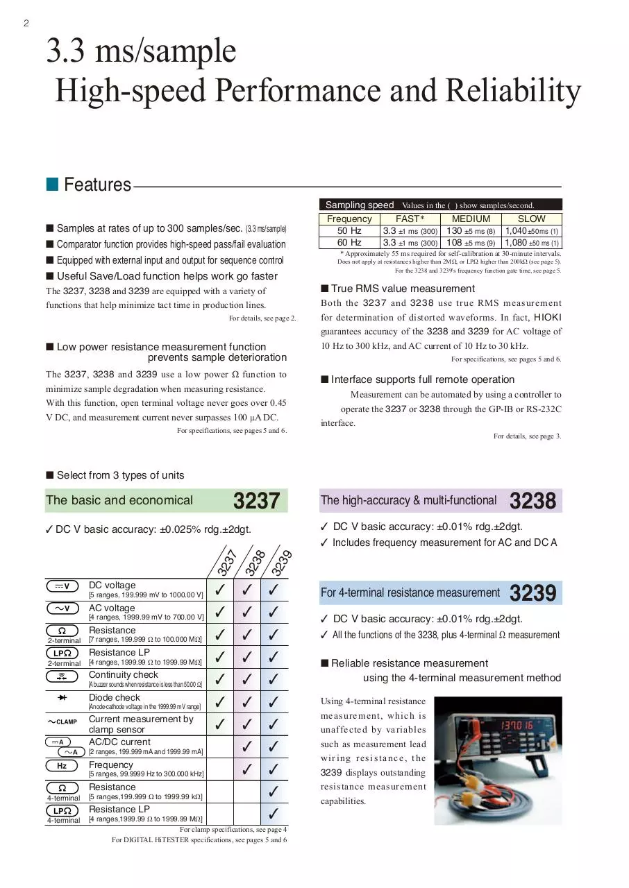
■ Reliable resistance measurement
using the 4-terminal measurement method
Using 4-terminal resistance
measurement, which is
unaffected by variables
such as measurement lead
wiring resistance, the
3239 displays outstanding
resistance measurement
capabilities.
Minimizing tact time with sequence
control
High-speed comparator and external input/output
■ EXT.I/O
Connector used: 57RE-40360-730B (D29) (DDK Ltd.)
Conforming connector: ADS-HC360001-010 (Honda Tsushin Kogyo Co., Ltd.),
57-30360 (DDK Ltd.) and other suitable connectors
Loading of saved settings from panel……LOAD 0 to 4
Measurement start trigger input…………TRIG
Measurement end signal output…………EOC
Comparator output…………………………Hi, IN, Lo
Internal power supply +5 V (max. 50 mA)……INT. DC V
Internal GND………………………….………INT. GND
● Comparator with external output
Input type: CMOS level
Signal voltage: Hi 3.8 V to 5.0 V, Lo 0 V (shorted) to 1.2 V
Logic: Negative logic (Low active)
Output type: Open collector
Applied voltage: Max. 35 V DC, 50 mA
Logic: Negative logic (Low active)
With free running measurement
You can set the upper and lower limits, and display one of 3
results: Hi, IN or Lo. In addition to LED and buzzer results,
open collector output results are provided through the external
input/output terminals.
X: measurement value, H: Upper limit, L: Lower limit
X > H…………………………Hi
H > X > L…………………IN
L > X………………Lo
MIN.
With external control
T1 Measurement trigger pulse width 500 µs
T2
Trigger delay time
Time
TYP.
MAX.
…
…
See below
FAST
See the table
Sampling time
MEDIUM
T3
at the top right of page 1.
using external control
SLOW
T4
Internal operation time
…
the end of measurement 500 µs
T5 Fromuntil
the next trigger
2.0 ms
…
…
…
…
1.7 ms
…
EOC Lo level time FAST
50 ms
…
T6 for free running MEDIUM …
measurement
SLOW
…
500 ms
…
FAST
Sampling time
See the table
T7 for free running MEDIUM
at the top right of page 1.
measurement
SLOW
■ Save/Load function for rapid response to various
work situations
You can save and recall a maximum of 30 DMM setting
conditions for various range and comparator values.
■ A trigger delay designed for measurement safety
The 3237, 3238 and 3239 are equipped with a trigger delay
function that can be set to manual or automatic for the time
period between trigger input and the display of the comparator
result (see T2 in the figure above).
Manual settings: Designate periods in terms of millisecond intervals between 0.000 s and 9.999 s
Automatic settings:
FAST
MEDIUM
SLOW
DC V
AC V
Ω (200Ω to 200 kΩ)
3 ms
500 ms
3 ms
3 ms
800 ms
3 ms
3 ms
1.5 s
3 ms
3
4
Automation of
Line Inspection
Available interfaces
■ GP-IB (option –01 specifications)
■ RS-232C (standard)
Purpose: Remote control and measurement value output
Standards conformance : IEEE -488.1 1987
Reference standard
: IEEE –488.2 1987
Purpose: Remote control and measurement value output
Transmission speed
(reference data)
Power line frequency: 60Hz
TRIG: EXT.Trig
Command: [:READ ?]
FAST MEDIUM SLOW
Transmission
7.0 ms 108 ms
speed
1,080
ms
Controller: PC-9801 RA (NEC)
OS: MS-DOS Ver. 3.30, N88-BASIC Ver. 6.0
Interface function:
SH1, AH1, T6, L4, SR1, RL1, PP0, DC1, DT1, CO
User code
User connector
: ASCII code
: 24-pin IEEE488 interface bus connector
Transmission system
Transmission speed
Data bit length
Stop bits
Parity bits
Delimiter
Handshaking
XON/XOFF
Connector
: Asynchronous method Full duplex
: 9600 bps (fixed)
: 8 bits
:1
: None
: CR+LF
: Hardware
: Not used
: 9-pin D-sub connector
All functions except switching the power on and off can be completely remote controlled and measurement data collected via either the
GP-IB or RS-232C interface
Please inquire regarding compatibility with the command sets of other manufacturers.
■ Output data to a printer (option)
When an RS-232C compatible PRINTER 9442 is connected,
you can print measurements by pressing the
key if in
manual trigger mode, or the
key if in internal trigger
(free run) mode.
Item No.
Measurement function
PRINTER 9442
CONNECTOR CABLE 9444
Cord length
approx 1.5m
AC ADAPTER 9443
Judgment
Measurement value
9443-02
(For the EU)
9443-01
(For Japan)
Please specify appropriate model
number suffix when ordering.
■ The printer can also be controlled using a foot switch.
As an alternative to pressing the
key or the
key, you
can also connect a foot switch to the external I/O TRIG terminal.
You can then initiate printing by stepping on the foot switch
(closing the circuit).
: Thermal serial dot matrix
: 112 mm
: 52.5cps
: AC ADAPTER 9443 or supplied nickel-hydride battery
(capable of printing about 3000 lines on full charge from
9443)
Dimensions and mass : Approx. 160W ✕ 66.5H ✕ 170D mm; approx. 580 g
Printing method
Paper width
Printing speed
Power supply
When you purchase a PRINTER 9442, you must also purchase a CONNECTION
CABLE 9444 and a AC ADAPTER 9443 to connect it to the DMM.
5
Efficient
Evaluation Testing
PC measurement using the high accuracy
and broad coverage of the 3238 and 3239
Example of data processing with Microsoft Excel
Time
Current
Integration
Time History Graph of Current Integration
Time
■ Highly accurate measurement
with minimal drift
Battery
Discharge Characteristics
The unit uses self-regulation to suppress drift.
Also, the DMM is ideal for collecting data over
extended periods of time.
■ Using Excel for efficient data
processing
The DMM supports fast data processing
by allowing you to transfer data directly to
a worksheet through either the GP-IB or
RS-232C interface.
Consult your nearest HIOKI dealer for details on software
■ Supports large AC current measurement by clamp sensor
■ Easy setup
Both the 3237, 3238 and 3239 can measure live line currents using an
optional clamp sensor. Enter the name of the clamp sensor being used
and display current values simply by selecting a range.
CLAMP ON SENSOR
9010 -50
9018 -50
9132-50
CONVERSION
ADAPTER 9704
Receive: BNC
Output: Banana
Rated current
Accuracy
(23ºC ± 3ºC, 45 to 66Hz)
Frequency characteristics
(deviation from the basic accuracy)
Max. permissible input
(cont.)
(45 to 66Hz)
Maximum rated voltage to earth
Measurable conductor diameter
Dimensions and mass
cord length 3m
(requires the 9704)
cord length 3m
(requires the 9704)
10/20/50/100/200/500 A
AC
cord length 3m
(requires the 9704)
20/50/100/200/500/1000 A
AC
± 2 % rdg. ± 1 % f.s.
± 1.5 % rdg. ± 0.1 % f.s.
± 3 % rdg. ± 0.2 % f.s.
at 40 Hz to 1 kHz
± 6 % (10, 20A range)
± 3 % (50 to 500A range)
at 40 Hz to 3 kHz
± 1 % max
at 40 Hz to 1 kHz
± 1 % max
150 Arms (10 to 50A ranges)
400 Arms (100, 200A ranges)
650 Arms (500A range)
1000 Arms
600 Vrms (850 Vpeak) insulated conductor
f 46 mm
Approx. 78W5188H535D mm, 420g
f 55 mm or 80520 mm bus bar
Approx. 100W5224H535D mm, 600g
Clamp sensor settings screen
Select 9010
Select the 20 A range.
From the menu's clamp sensor selection screen, select the name
of the sensor with the cursor key and press the
key.
Then, select the same range as you set for the sensor with the
cursor key.
* The accuracy of the clamp sensors shown on the left (when used with the
DMM) is calculated by taking: the difference in the AC V accuracy for the
DMM (dgt.) ✕ 10 (dgt.).
For the AC V accuracy of the DMM, see page 6.
In addition to the sensors described above, you can also connect the 3283, 3284, 3285 (requires the 9094) Clamp On HiTesters, and the 9277, 9278, 9279 (requires the 9555-10) DC Sensors.
6
■ 3237, 3238, 3239 common specifications (Accuracy guaranteed for 1 year, Post-adjustment accuracy guaranteed for 1 year)
● DC voltage (DC V)
Range Resolution Full scale
Input impedance Overload protection
200 mV 1 µV 199.999mV Greater than 100MΩ
1000 V DC
2000 mV 10 µV 1999.99mV Greater than 100MΩ
750 V AC
20
V 100 µV 19.9999 V Appox. 11 MΩ
However, less than
200 V 1 mV 199.999 V Appox. 10 MΩ
107 V Hz
1000 V 10 mV 1000.00 V Appox. 10 MΩ
● AC voltage (AC V)
Range Resolution Full scale
2000 mV 10 µV 1999.99mV
20
V 100 µV 19.9999 V
200 V 1 mV 199.999 V
700 V 10 mV
750.00 V
● Resistance (Ω) 2-terminal measurement
● Resistance (Ω) at Low Power function 2-terminal measurement
Range Resolution Full scale
Current Open terminal voltage Overload protection
200 Ω 1 mΩ 199.999 Ω Appox. 1 mA 6V DC max.
2000 Ω 10 mΩ 1999.99 Ω Appox. 1 mA 6V DC max.
20 kΩ 100 mΩ 19.9999kΩ Appox. 100µA 6V DC max.
200 kΩ 1
Ω 199.999kΩ Appox. 10µA 6V DC max. 500Vpeak
2000 kΩ 10 Ω 1999.99kΩ Appox. 1 µA 6V DC max.
20 MΩ 100 Ω 19.9999MΩ Appox. 100nA 6V DC max.
100 MΩ 1 kΩ 100.000MΩ Appox. 20nA 6V DC max.
For fast sampling in the 20 MΩ range or higher.
Frequency FAST*
MEDIUM
SLOW
50 Hz 20 ±1 ms 170 ±5 ms 1,360 ±50 ms
60 Hz 16.7 ±1 ms 142 ±5 ms 1,420 ±50 ms
Range Resolution Full scale
2000 Ω 10 mΩ 1999.99 Ω
20 kΩ 100 mΩ 19.9999kΩ
200 kΩ 1
Ω 199.999kΩ
2000 kΩ 10 Ω 1999.99kΩ
Current
Appox. 100µA
Appox. 10µA
Appox. 1 µA
Appox. 100nA
Open terminal voltage Overload protection
0.45V DC max.
0.45V DC max.
0.45V DC max.
0.45V DC max.
500Vpeak
● Continuity check
Range Resolution Full scale
Current Open terminal voltage Overload protection
2000 Ω 10 mΩ 1999.99 Ω Appox. 100µA 0.45V DC max. 500 Vpeak
For sampling at in the 2 MΩ range or
the LPΩ 200 kΩ.range or higher
Frequency
Input impedance Overload protection
Appox. 1 MΩ
600 V DC
Appox. 1 MΩ 750 V rms, 1000Vpeak
Appox. 1 MΩ
However, less than
107 V Hz
Appox. 1 MΩ
A built-in buzzer sounds when the resistance value is less than 50.00 Ω.
FAST*
● Diode check
50 Hz 20 ±1 ms
60 Hz 16.7 ±1 ms
Range Resolution Full scale
Current Open terminal voltage Overload protection
2000 mV 10 µV 1999.99mV Appox. 1 mA 6V DC max. 500 Vpeak
* Approximately 55 ms required for self-calibration at 30-minute intervals.
■ 3238, 3239 specifications (Accuracy at 23˚C±5˚C (73˚F±9˚F), 80% rh or less)
● DC current (DC A) Accuracy %, ppm=reading error, d=digit error
● AC/DC current (A)
Range Resolution Full scale Internal resistance Overload protection
200 mA 1 µA 199.999mA
Appox. 1 Ω
250V, 2A fuse
2000 mA 10 µA 1999.99mA Appox. 100 m Ω
Range
200 mA
2000 mA
● AC current (AC A) 200mA range Accuracy %, ppm=reading error, d=digit error
Range
Frequency
10 Hz to 20 Hz
20 Hz to 45 Hz
45 Hz to 300 Hz
All
Ranges 300 Hz to 1 kHz
1 kHz to 3 kHz
3 kHz to 10 kHz
10 kHz to 30 kHz
SLOW
±1.0%±200d
±0.4%±200d
±0.3%±100d
±0.3%±100d
±0.3%±100d
±0.5%±300d
±1.0%±300d
Sampling
MEDIUM
undefined
undefined
±0.5%±200d
±0.4%±200d
±0.4%±200d
±0.5%±300d
±1.0%±300d
FAST
undefined
undefined
undefined
±0.4%±300d
±0.4%±300d
±0.5%±400d
±1.0%±400d
SLOW
±0.1 %±6d
±0.15%±6d
Sampling
MEDIUM
±0.1 %±10d
±0.15%±10d
Thermal
coefficient
±100ppm±0.6d
±150ppm±0.6d
FAST
±0.1 %±300d
±0.15%±300d
● AC current (AC A) 2000mA range Accuracy
Thermal
coefficient
±0.1 %±20d
±400ppm±20d
±300ppm±10d
±300ppm±10d
±300ppm±10d
±500ppm±30d
±0.1 %±30d
SLOW
±1.2%±200d
±0.6%±200d
±0.4%±100d
±0.4%±100d
±0.6%±200d
±1.2%±300d
undefined
Sampling
MEDIUM
undefined
undefined
±0.6%±200d
±0.6%±200d
±0.6%±200d
±1.2%±300d
undefined
FAST
undefined
undefined
undefined
±0.6%±300d
±0.6%±300d
±1.2%±400d
undefined
Thermal
coefficient
±0.12%±20d
±600ppm±20d
±400ppm±10d
±400ppm±10d
±600ppm±20d
±0.12%±30d
undefined
Specified input is 16 mA or higher
Specified input is 160 mA or higher
Additional error due to crest factor: 1<CF<2: ±200d, 2<CF<3: ±500d, 3<CF: Outside the assured accuracy range
● Frequency (Hz) Source is AC V only and input level is higher than 8% of full scale
Range Resolution Full scale Internal resistance Min. measurement Overload protection
100 Hz 0.1 mHz 99.9999 Hz Appox. 1M Ω
10 Hz
600 V DC
1 kHz 1 mHz 999.999 Hz Appox. 1M Ω
10 Hz
750 V rms,
10 kHz 10 mHz 9.99999kHz Appox. 1M Ω
10 Hz
1000Vpeak
100 kHz 100mHz 99.9999kHz Appox. 1M Ω
10 Hz
However, less
than 107 V Hz
300 kHz 1 Hz 999.999kHz Appox. 1M Ω
10 Hz
● Frequency (Hz) Accuracy %, ppm=reading error, d=digit error
For all gate times
Square-wave input between 10 Hz to 300 kHz, 10 V p-p.
±0.015% ±2d
All Ranges
Range
Frequency gate time
FAST
15 ±6 ms
MEDIUM
110 ±10 ms
Thermal
coefficient
±5 ppm
SLOW
1,010 ±20 ms
Measurement time: from gate time to the input signal period ✕ 2
■ 3239 specifications (Accuracy at 23˚C±5˚C (73˚F±9˚F), 80% rh or less)
● Resistance (Ω) 4-terminal measurement
Range Resolution Full scale
Current Open terminal voltage Overload protection
200 Ω 1 mΩ 199.999 Ω Appox. 1 mA 6V DC max.
V, Ω terminal
2000 Ω 10 mΩ 1999.99 Ω Appox. 1 mA 6V DC max. 500Vpeak
20 kΩ 100 mΩ 19.9999kΩ Appox. 100µA 6V DC max.
200 kΩ 1
Ω 199.999kΩ Appox. 10µA 6V DC max. SENSE terminal
400Vpeak
2000 kΩ 10 Ω 1999.99kΩ Appox. 1 µA 6V DC max.
● Resistance (Ω) at Low Power function 4-terminal measurement
Range Resolution Full scale
2000 Ω 10 mΩ 1999.99 Ω
20 kΩ 100 mΩ 19.9999kΩ
200 kΩ 1
Ω 199.999kΩ
2000 kΩ 10 Ω 1999.99kΩ
Current
Appox. 100µA
Appox. 10µA
Appox. 1 µA
Appox. 100nA
Open terminal voltage Overload protection
0.45V DC max.
0.45V DC max.
0.45V DC max.
0.45V DC max.
V, Ω terminal
500Vpeak
SENSE terminal
400Vpeak
7
● 3237 DC voltage (DC V) Accuracy %, ppm=reading error, d=digit error
Range
200 mV
2000mV
20
V
200 V
1000 V
SLOW
±0.026%±6d
±0.025%±2d
±0.028%±5d
±0.028%±2d
±0.028%±2d
Sampling
MEDIUM
±0.026%±10d
±0.025%±8d
±0.028%±10d
±0.028%±8d
±0.028%±8d
Thermal
coefficient
±20ppm±0.6d
±15ppm±0.2d
±20ppm±0.5d
±20ppm±0.2d
±20ppm±0.2d
FAST
±0.035%±300d
±0.03%±100d
±0.035%±100d
±0.035%±100d
±0.035%±100d
CMRR (50/60Hz Rl=1kΩ): SLOW 130dB, MEDIUM 90dB, FAST 20dB
● 3238, 3239 DC voltage (DC V) Accuracy %, ppm=reading error, d=digit error
SLOW
±0.012%±6d
±0.01 %±2d
±0.016%±5d
±0.016%±2d
±0.016%±2d
Sampling
MEDIUM
FAST
±0.012%±10d ±0.02%±300d
±0.01 %±8d ±0.015%±100d
±0.016%±10d ±0.02%±100d
±0.016%±8d ±0.02%±100d
±0.016%±8d ±0.02%±100d
NMRR (50/60Hz ): SLOW 70dB, MEDIUM 50dB, FAST 0dB
● 3238, 3239 AC V Accuracy %, ppm=reading error, d=digit error
● 3237 AC voltage (AC V) Accuracy %, ppm=reading error, d=digit error
Sampling
Thermal
coefficient
SLOW
MEDIUM
FAST
SLOW
10 Hz to 20 Hz ±1.5%±200d
undefined
undefined
±0.15%±20d ±0.8%±200d
20 Hz to 45 Hz ±0.5%±200d
undefined
undefined
±500ppm±20d ±0.2%±200d
45 Hz to 300 Hz ±0.2%±100d ±0.5%±300d
undefined
±200ppm±10d ±0.1%±100d
300 Hz to 3 kHz ±0.2%±100d ±0.2%±200d ±0.2%±300d ±200ppm±10d ±0.1%±100d
All
3 kHz to 10 kHz ±0.3%±200d ±0.3%±200d ±0.3%±300d ±300ppm±20d ±0.1%±100d
Ranges
10 kHz to 30 kHz ±1.5%±600d ±1.5%±600d ±1.5%±700d ±0.15%±60d ±0.3%±400d
30 kHz to 50 kHz
undefined
undefined
undefined
undefined
±0.3%±400d
50 kHz to 100kHz
undefined
undefined
undefined
undefined
±1.5%±1000d
100kHz to 300kHz
undefined
undefined
undefined
undefined
±5.0%±5000d
The accuracy above is standard for inputs higher than 8% of full scale (higher than 160 V for a range of 750 V).
Range
Thermal
coefficient
±12ppm±0.6d
±10ppm±0.2d
±16ppm±0.5d
±16ppm±0.2d
±16ppm±0.2d
Frequency
Sampling
MEDIUM
undefined
undefined
±0.3%±200d
±0.1%±200d
±0.1%±200d
±0.3%±400d
±0.3%±400d
±1.5%±1000d
±5.0%±5000d
FAST
undefined
undefined
undefined
±0.1%±300d
±0.1%±300d
±0.3%±500d
±0.3%±500d
±1.5%±1100d
±5.0%±5000d
Thermal
coefficient
±800ppm±20d
±200ppm±20d
±100ppm±10d
±100ppm±10d
±100ppm±10d
±300ppm±40d
±300ppm±40d
±0.15%±100d
±0.5%±500d
Additional error due to crest factor: 1<CF<2: ±200d, 2<CF<3: ±0.2%rdg.±500d(3237), ±500d(3238, 3239), 3<CF: Outside the assured accuracy range
● 3238, 3239 Resistance (Ω) Accuracy %, ppm=reading error, d=digit error
● 3237 Resistance (Ω) Accuracy %, ppm=reading error, d=digit error
Measurement
Range
200 Ω
2000 Ω
20 kΩ
2terminal 200 kΩ
measurement 2000 kΩ
20 MΩ
100 MΩ
SLOW
±0.05 %±8d
±0.05 %±2d
±0.05 %±2d
±0.05 %±2d
±0.05 %±2d
±0.3 %±4d
±3.0 %±10d
Sampling
MEDIUM
±0.05 %±18d
±0.05 %±12d
±0.05 %±12d
±0.05 %±12d
±0.05 %±12d
±0.3 %±20d
±3.0 %±50d
FAST
±0.05%±300d
±0.05%±100d
±0.05%±100d
±0.05%±200d
±0.05%±200d
±0.3 %±200d
±3.0 %±500d
Thermal
coefficient
±50ppm±0.8d
±50ppm±0.2d
±50ppm±0.2d
±50ppm±0.2d
±50ppm±0.2d
±300ppm±0.4d
±0.3%±1d
SLOW
±0.03 %±8d
±0.02 %±2d
±0.02 %±2d
±0.02 %±2d
±0.03 %±2d
±0.2 %±4d
±3.0 %±10d
Sampling
MEDIUM
±0.03 %±18d
±0.02 %±12d
±0.02 %±12d
±0.02 %±12d
±0.03 %±12d
±0.2 %±20d
±3.0 %±50d
FAST
±0.03%±300d
±0.02%±100d
±0.02%±100d
±0.02%±200d
±0.03%±200d
±0.2 %±200d
±3.0 %±500d
Thermal
coefficient
±30ppm±0.8d
±20ppm±0.2d
±20ppm±0.2d
±20ppm±0.2d
±30ppm±0.2d
±200ppm±0.4d
±0.3%±1d
After zero adjustment. When measuring high resistance, use a shielded cable such as the 9236 CONNECTION CORD (1.7m).
● 3237 Resistance (Ω) Accuracy at Low Power function
Measurement
Range
2000 Ω
20 kΩ
terminal 200 kΩ
measurement 2000 kΩ
2-
SLOW
±0.05 %±6d
±0.05 %±6d
±0.05 %±6d
±0.3 %±6d
Sampling
MEDIUM
±0.05 %±14d
±0.05 %±14d
±0.05 %±14d
±0.3 %±20d
● 3238, 3239 Resistance (Ω) Accuracy at Low Power function
FAST
±0.05 %±300d
±0.05 %±300d
±0.05 %±300d
±0.3 %±500d
Thermal
coefficient
±50ppm±0.6d
±50ppm±0.6d
±50ppm±0.6d
±300ppm±0.6d
SLOW
±0.02 %±6d
±0.02 %±6d
±0.02 %±6d
±0.2 %±6d
Sampling
MEDIUM
±0.02 %±14d
±0.02 %±14d
±0.02 %±14d
±0.2 %±20d
FAST
±0.02%±300d
±0.02%±300d
±0.02%±300d
±0.2 %±300d
Thermal
coefficient
±20ppm±0.6d
±20ppm±0.6d
±20ppm±0.6d
±200ppm±0.6d
After zero adjustment. When measuring high resistance, use a shielded cable such as the 9236 CONNECTION CORD (1.7m).
● 3237 Continuity check Accuracy %, ppm=reading error, d=digit error
Sampling
Range
● 3237 Diode check Accuracy %, ppm=reading error, d=digit error
Range
2000 Ω
SLOW
±0.025% ±2d
Sampling
MEDIUM
±0.025% ±8d
Sampling
Thermal
coefficient
±50ppm±0.6d
FAST only
±0.05 %±300d
2000 Ω
● 3238, 3239 Continuity check Accuracy %, ppm=reading error, d=digit error
FAST
±0.03% ±100d
● 3238, 3239 Diode check Accuracy %, ppm=reading error, d=digit error
Thermal
coefficient
±15ppm±0.2d
SLOW
±0.01 %±2d
4-terminal measurement
Range
200 Ω
2000 Ω
terminal 20 kΩ
measurement 200 kΩ
2000 kΩ
4-
SLOW
±0.03 %±8d
±0.02 %±2d
±0.02 %±2d
±0.02 %±2d
±0.03 %±2d
Sampling
MEDIUM
±0.03 %±18d
±0.02 %±12d
±0.02 %±12d
±0.02 %±12d
±0.03 %±12d
The accuracy quoted above is for a contact resistance of 100 Ω or less.
FAST
±0.03 %±300d
±0.02 %±100d
±0.02 %±100d
±0.02 %±200d
±0.03 %±200d
Sampling
MEDIUM
±0.01 %±8d
FAST
±0.015%±100d
Thermal
coefficient
±10ppm±0.2d
4-terminal measurement
● Resistance (Ω) Accuracy %, ppm=reading error, d=digit error
Measurement
Thermal
coefficient
±20ppm±0.6d
FAST only
±0.02 %±300d
● Resistance (Ω) Accuracy at Low Power function
Thermal
coefficient
±30ppm±0.8d
±20ppm±0.2d
±20ppm±0.2d
±20ppm±0.2d
±30ppm±0.2d
SLOW
No range
±0.02 %±6d
±0.02 %±6d
±0.02 %±6d
±0.2 %±6d
Sampling
MEDIUM
No range
±0.02 %±14d
±0.02 %±14d
±0.02 %±14d
±0.2 %±20d
FAST
No range
±0.02%±300d
±0.02%±300d
±0.02%±300d
±0.2 %±300d
Thermal
coefficient
No range
±20ppm±0.6d
±20ppm±0.6d
±20ppm±0.6d
±200ppm±0.6d
■ 3237, 3238, 3239 General Specifications
● AC measurement: True RMS value measurement
● Crest factor: 3.0 max.
● Ancillary functions: Comparator, Average (0 to 99 times), Zero Adjust, Trigger (the display changes when the trigger is activated),
and the Save/Load functions. (Up to 30 types of setting conditions)
● Interface: External input/output, RS-232C and GP-IB (option -01 specifications)
● Display: LED max. 199999 (999999 for frequency)
● Sampling rate (see page 1): SLOW approx. 1 samples/s
MEDIUM approx. 8 to 9 samples/s
FAST approx. 300 samples/s (Does not apply at resistances higher than 2MΩ, or LPΩ higher than 200kΩ)
(self-calibration takes place for approximately 55 ms at 30-minute intervals for FAST sampling only.)
● Range selection: Auto and Manual
● Applicable standards: Safety: EN61010-1, EN61010-031
Lo terminal: CAT II (300V)
Hi terminal: CAT II (600V)
EMC: EN61326-1, EN61000-3-2, EN61000-3-3
● Ambient temperature of use: 0 to 40 ˚C(32˚F to 104˚F) 80%RH (no condensation)
● Storage temperature range: -10 to 50˚C(-14˚F to 122˚F) 70%RH (no condensation)
● Power supply: Select from AC 100 V/120 V/220 V/240 V, (50/60 Hz) specify when ordering
● Maximum rated power: 15 VA
● Dimensions and mass: Approx. 215 W✕80 H✕265 D mm, 2.6kg
Approx 8.5˝ W ✕ 3.5˝ H ✕10.4˝ D, 91.7 oz.
Options
DIGITAL HiTESTER (Economical Type)
Order Code:
3237
3237-01
RS-232C cable
RS-232C CABLE 9637 (9pin-9pin, Reverse type/1.8m)
RS-232C CABLE 9638 (9pin-25pin, Reverse type/1.8m)
(with RS-232C interface)
(with GP-IB, RS-232C)
DIGITAL HiTESTER (Advanced Type)
Order Code:
3238
3238-01
GP-IB cable
The specifications of the 3237, 3238 and 3239 are –01 specifications
GP-IB CABLE 9151-02 (2m)
(with RS-232C interface)
(with GP-IB, RS-232C)
Printer
PRINTER
9442
CONNECTOR CABLE 9444 (For 9442 printer)
AC ADAPTER
9443-01 (For 9442 printer, Japan)
AC ADAPTER
9443-02 (For 9442 printer, EU)
RECORDING PAPER 1196 (For printer, 10 rolls)
DIGITAL HiTESTER (4-terminal Ω function & Advanced Type)
Order Code:
3239
3239-01
(with RS-232C interface)
(with GP-IB, RS-232C)
When you purchase a PRINTER 9442, you must also purchase a 9444 CONNECTOR
CABLE and an AC ADAPTER 9443 to connect it to the DMM.
For printer specifications, see page 3.
cord length 90cm
TEST LEAD L9170-10 (included)
4-Terminal Ω measurement probe for 3239
9010-50
Options
Clamp sensors
CLAMP ON PROBE 9010-50 (10/20/50/100/200/500A AC )
CLAMP ON PROBE 9018-50 (10/20/50/100/200/500A AC, Broadband type)
CLAMP ON PROBE 9132-50 (20/50/100/200/500/1000A AC )
For Clamp sensors specifications, see page 4.
CLIP-TYPE LEAD 9287-10 (Approx. 85 cm between connectors, and 8 cm between probes)
CLIP-TYPE LEAD 9452 (Approx. 80 cm between connectors, and 20 cm between probes)
FOUR-TERMINAL LEAD 9453 (Approx. 80 cm between connectors, and 30 cm between probes)
PIN-TYPE LEAD 9461 (Approx. 40 cm between connectors, and 25 cm between probes)
9287-10
9452
9453
9461
Note: Company names and Product names appearing in this catalog are trademarks or registered trademarks of various companies.
HIOKI (Shanghai) SALES & TRADING CO., LTD.
TEL +86-21-63910090 FAX +86-21-63910360
http://www.hioki.cn / E-mail: info@hioki.com.cn
РАДАР - ОФИЦИАЛЬНЫЙ ДИЛЕР HIOKI
HIOKI INDIA PRIVATE LIMITED
TEL +91-124-6590210
HEADQUARTERS
E-mail: hioki@hioki.in
81 Koizumi, Ueda, Nagano, 386-1192, Japan
TEL +81-268-28-0562 FAX +81-268-28-0568
HIOKI SINGAPORE PTE. LTD.
http://www.hioki.com / E-mail: os-com@hioki.co.jp TEL +65-6634-7677 FAX +65-6634-7477
E-mail: info-sg@hioki.com.sg
HIOKI USA CORPORATION
HIOKI KOREA CO., LTD.
TEL +1-609-409-9109 FAX +1-609-409-9108
TEL +82-2-2183-8847 FAX +82-2-2183-3360
http://www.hiokiusa.com / E-mail: hioki@hiokiusa.com E-mail: info-kr@hioki.co.jp
All information correct as of Sept. 16, 2015. All specifications are subject to change without notice.
РОССИЯ, 198152, Санкт-Петербург
Краснопутиловская ул., д.25
Тел./факс +7 (812) 600-48-89
Тел.: +7 (812) 375-32-44
www.radar1.ru
3239E8-59M
Printed in Japan
info@radar1.ru
Download HIOKI 3237 ENG
HIOKI_3237_ENG.pdf (PDF, 3.34 MB)
Download PDF
Share this file on social networks
Link to this page
Permanent link
Use the permanent link to the download page to share your document on Facebook, Twitter, LinkedIn, or directly with a contact by e-Mail, Messenger, Whatsapp, Line..
Short link
Use the short link to share your document on Twitter or by text message (SMS)
HTML Code
Copy the following HTML code to share your document on a Website or Blog
QR Code to this page

This file has been shared publicly by a user of PDF Archive.
Document ID: 0000326475.