HIOKI DT4282 ENG (PDF)
File information
Title: DIGITAL MULTIMETER DT4200 Series
Author: HIOKI
This PDF 1.7 document has been generated by Adobe InDesign CS5.5_J (7.5.3) / Adobe PDF Library 9.9, and has been sent on pdf-archive.com on 24/12/2015 at 15:44, from IP address 5.18.x.x.
The current document download page has been viewed 412 times.
File size: 6.31 MB (16 pages).
Privacy: public file


File preview
DIGITAL MULTIMETER DT4200 Series
DMM / Testers
Super Fast Response Rate and Safety Features
Take Professional Testing to a Higher Level
Made in Japan for rock-solid quality.
2
Hazard
1
Prevent unavoidable debris from shorting the
measurement target and causing an accident.
The DT4255’s voltage input terminals incorporate a
protective fuse so that contamination of the instrument’s
internal components with iron powder or other particulate
matter will not result in an internal short-circuit. The fuse can
be replaced easily on site.
Hazard
3
Wrong insertion
may lead to short-circuits.
Hazard
2
Continued high input may result in major
accidents such as fire.
To prevent an accident, a warning function immediately
notifies the operator if the DMM receives excessively high
input.
*Red screen available on high-end models only.
Hazard
4
Mistakenly measuring voltage using the
current range may lead to a short-circuit.
A range: Only the A and COM terminal inlets open.
V range: Only the V and COM terminal inlets open.
The DT4281 and DT4282 use terminal shutters to keep
probes from being inserted into the wrong inlets. The
shutters block whichever terminal is not being used based
on the selected measurement function.
The DT4281, DT4253, DT4255, and DT4256 eliminate the
root cause of such accidents by providing clamp-on sensorbased current measurement functionality instead of using
conventional probes.
3
Safe testers that protect
workers from dangerous accidents
Engineered based on extensive customer feedback,
the Hioki Digital Multimeter DT4200 series delivers the design
and quality needed in order to ensure safety in field measurement.
Measurement categories
Service
connection
Service
wires
Safe measurement requires use of an instrument
that suits the measurement location.
Distribution
panel
Distribution
panel
Outlet
Power meter
Transformer
Fixed
equipment
Outlet
Buried wires
CAT IV
Terminal-to-ground voltage
Electric
wires
Distribution
panel
Pole-mounted
transformer
L1
100V
100V
Service wires
To ensure operators’ ability to use measuring instruments safely,
IEC 61010 classifies the locations in which instruments are used
into a series of safety-based measurement categories (ranging
from CAT II to CAT IV). Using an instrument that does not satisfy
the required safety level can lead to an electrical accident.
Line voltage:
100 V
Line voltage:
200 V
N
L2
TV: 100 V
Line voltage:
100 V
Air conditioner: 200 V
Ground (0 V)
600 V
Terminal-to-ground voltage
Measurement category
suited to the location of use
High-end models
CAT III 1000 V / CAT IV 600 V
Standard models
CAT III 1000 V / CAT IV 600 V
Pocket models
CAT III 600 V
/ CAT IV 300 V
Designed and manufactured in Japan to
ensure high quality and guaranteed with a
3-year warranty for peace of mind
All development, design, and manufacturing processes for
almost all Hioki digital multimeters are carried out at our
Head Office in Nagano Prefecture. Some of the industry’s
most advanced technological capabilities enable us to
deliver products of the highest possible quality.
3-year
warranty
4
5
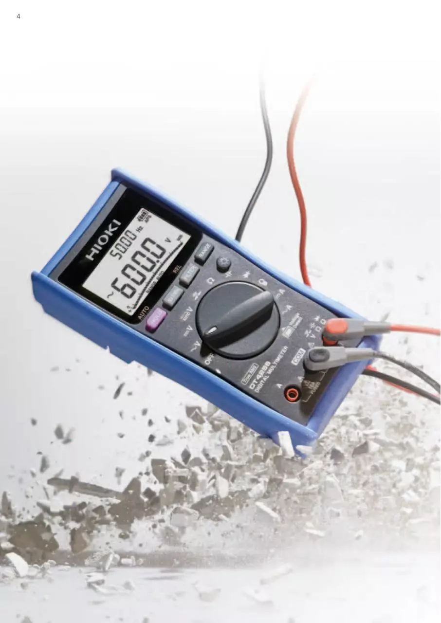
Field-Proven Strength and Usability
DT4200 series
Robust design capable of withstanding a drop from a
height of 1 m onto concrete
Drop tester
To test our products’ ability to
withstand mechanical shock,
we repeatedly drop them from
a height of at least 1 m until
they break. This drop-testing
regime leads to more robust
products by fostering a series
of design improvements.
Fast, accurate measurement of the output voltage on the
secondary side of an inverter
With low-pass filter off With low-pass filter on
Preventing instrument failure by keeping out dust
If dust gets into the instrument’s
enclosure, it can cause the device to
fail. Since dust can get into the
instrument especially easily through
the gap around the rotary switch, the
DT4200 series incorporates a dustproof part known as an O-ring where
the rotary switch is mounted to
improve the device’s dust resistance.
True RMS measurement for accurate measurement of
even distorted current waveforms
Average-value method True RMS method
measured value
measured value
The DT series can accurately measure the voltage on the secondary
side of an inverter, just like a power meter. Its low-pass filter rejects
harmonic components so that the fundamental wave can be isolated
and accurately measured.
Current waveforms are often distorted, causing the average-value
and true RMS measurement methods to yield different results. To
obtain accurate readings, RMS measurement is indispensable.
Outstanding viewing angle so display is easy to read at
an angle or even in a dim location
Rotary switch that’s easy to operate even when
wearing gloves
The DT4200 series features a display
with a wide viewing angle and a
backlight function so that it’s easy to
read, even when you can’t view the
screen from the front or when making
measurements in a dim location.
The DT4200’s rotary switch is
designed to be easy to turn even
when wearing thick work gloves, for
example while working in hazardous
measurement locations or harsh
conditions.
Outstanding hands-free ease of use in the field when working with numerous measurement locations
Secure the instrument
on the wall so that you
don’t have to hold it.
It’s hard to carry out work tasks smoothly
when you’re juggling a measuring instrument,
probes, recording paper, and other supplies.
Field concerns like these are resolved by the
DT4200’s magnetic strap, auto-hold function,
and ability to save results in its internal
memory. These capabilities boost work
efficiency and help reduce work times.
The display automatically Press the MEM key to
stops once the measured save measured values in *The auto-hold function is available exclusively in high-end
value stabilizes.
the instrument’s internal and standard models. The ability to save results in internal
memory.
memory is available exclusively in high-end models.
Extensive selection of probe tips that you can choose based on the measurement location, improving ease of measurement
With the DT4200, you can choose the probe
type that best suits your measurement
location, making it possible to measure in
areas that can’t be reached with conventional
probes and busbars that you wish to clamp
between probes.
With screw terminals
In deep-set locations
that can’t be reached
with other probes
*Compatible probe tips vary with the DMM model. Please
For clamping around the see page 16. The optional Connection Cable L4930 is
target busbar
required in order to use the probes shown at the left.
6
High-end models
Featuring high accuracy, extensive additional functionality,
and a broad range of measurement parameters
DCV typical accuracy: ±0.025% rdg. ±2 dgt.
Measurement categories: CAT III (1000 V) / CAT IV (600 V)
For electrical
work in the field
For laboratory and
research use
Designed for maximum safety in the
field when measuring current with
clamp-on sensors.
Designed for use in laboratories and
R&D applications where you wish to
measure a wide variety of parameters.
DT4281
DT4282
DC voltage
60.000 mV to 1000.0 V
DC voltage
60.000 mV to 1000.0 V
AC voltage
60.000 mV to 1000.0 V
AC voltage
60.000 mV to 1000.0 V
DC + AC voltage
6.000 V to 1000.0 V
DC + AC voltage
6.000 V to 1000.0 V
DC current
600.00 μA to 600.00 mA
DC current
600.00 μA to 10.000 A
AC current
600.00 μA to 600.00 mA
AC current
600.00 μA to 10.000 A
AC clamp-on measurement
Frequency
AC clamp-on measurement
Frequency
Resistance
Continuity check
Resistance
Continuity check
Temperature
Diode test
Temperature
Diode test
Capacitance
Conductance
Capacitance
Conductance
AC/DC automatic detection Voltage detection function
Supported measurement parameter
AC/DC automatic detection Voltage detection function
Supported measurement parameter (with model-specific variations)
Unsupported measurement parameter
*The range figures given indicate the instrument’s measurement ranges (not the range of measurable values).
7
Applications
Magnetic strap frees both hands
for work
Using the magnetic strap (option)
By using the magnetic strap to secure the
instrument to the wall, you can free both
hands so that you can more easily record
measured values, significantly boosting work
efficiency.
Automatically hold display values
and save results with one touch to
the DMM’s internal memory
The display is automatically held once the
measured value stabilizes. You can save
measurement results to the instrument’s
internal memory simply by pressing the MEM
key, making it easy to read and record values
during inspection work.
Manage measurement data on a
computer
Using the Communication Package DT4900-01 (option)
Measurement results can be downloaded to
a computer via a USB connection. Once
downloaded, you can save them as a file
(text format) or display them as a graph using
the desired interval. Results can also be sent
in real time while measurement is ongoing.
*The computer and multimeter are electrically
isolated by means of optical communications so that
data can be sent with peace of mind.
Measure output voltage on the
secondary sides of inverters
Ripple voltage confirmation of DC
charging systems
Accurately measure the fundamental wave
alone by eliminating harmonic components with
the DMM’s low-pass filter function.
High-end models can detect ripple voltage
with a superposed DC signal.
With low-pass filter off
Peak value measurement / DC + AC voltage
measurement
Percentage display for
instrumentation signal measurement
4 to 20 mA / 0 to 20 mA percentageequivalent display
You can check percentage-equivalent values.
With low-pass filter on
114.1 V
85.9 V
*DC + AC value =
Fundamental component
Fundamental component
Harmonic component
Harmonic component
+
+
20 mA
100%
Output 2
Display
20 mA
100%
√
4 mA
100 V
DC + AC measurement*
0V
Display
4 mA
Input
waveform
0V
Output 1
100.49 V
(AC)2 + (DC)2
+Peak measurement
114.10 V
-Peak measurement
85.90 V
0%
0%
Temperature
Pressure
Flow rate
Transducer
Display refresh rate Maximum/minimum
value display
Change the display
Measure very low currents used by
gas-burning devices
DC μA range
High-end models provide a DC 600.00 μA
range for measuring burner flame currents.
Burner
Intuitive notification of continuity check
results and excessively high input with
a red screen backlight and beep
Check the maximum and
minimum measured
values shown on the
display after pressing
the MAX/MIN button.
Relative display
Decibel conversion
View relative values
using the display value
before the relative
function was enabled as
the reference.
Convert the results of AC
voltage measurement to a
decibel value relative to a
reference value and
display the results (dbm/
dbv).
High-end models notify the operator of continuity
check results and excessively high input with a
red screen backlight and beep, making it
possible to check measurement results intuitively.
Flame sensor
rod
Insulator
Control
board
refresh speed to
stabilize the display
when performing
measurement
characterized by a high
level of variability.
Continuous state
Excessively high input
8
Featuring the world’s fastest DMM engine*
The DT4200 series features a dedicated IC that Hioki developed
in-house in order to deliver unprecedented measurement speed.
*According to Hioki research conducted in April 2015.
Standard models
Introducing a line of field-optimized instruments that
can be chosen based on the application at hand
DCV typical accuracy: ±0.3% rdg. ±3 dgt.
Measurement categories: CAT III (1000 V) / CAT IV (600 V)
For laboratory
and
research use
DT4252
For laboratories and R&D
applications where you
wish to measure a wide
variety of parameters.
For instrumentation
4-20mA
DT4253
Measure
instrumentation, airconditioning equipment,
and gas-burning
devices.
Voltage
measurement
only model
DT4254
Measure photovoltaic
modules and other
high-voltage targets at
up to 1700 V DC.
For electrical
work in the field
DT4255
Designed for
maximum safety with
voltage measurement
terminals that are
protected by a fuse.
Multifunction
model
DT4256
Delivers maximum
functionality for use
in a wide range of
settings.
DC voltage
600.0 mV to 1000 V
DC voltage
600.0 mV to 1000 V
DC voltage
600.0 mV to 1500 V
DC voltage
600.0 mV to 1000 V
DC voltage
600.0 mV to 1000 V
AC voltage
6.000 V to 1000 V
AC voltage
6.000 V to 1000 V
AC voltage
6.000 V to 1000 V
AC voltage
6.000 V to 1000 V
AC voltage
6.000 V to 1000 V
DC + AC voltage
DT4281/4282 only
DC + AC voltage
DT4281/4282 only
DC + AC voltage
DT4281/4282 only
DC + AC voltage
DT4281/4282 only
DC + AC voltage
DT4281/4282 only
DC current
6.000 A to 10.00 A
DC current
60.00 μA to 60.00 mA
DC current
n/a
DC current
n/a
DC current
60.00 mA to 10.00 A
AC current
6.000 A to 10.00 A
AC current
n/a
AC current
n/a
AC current
n/a
AC current
600.0 mA to 10.00 A
AC clamp-on
measurement
Frequency
AC clamp-on
measurement
Frequency
AC clamp-on
measurement
Frequency
AC clamp-on
measurement
Frequency
AC clamp-on
measurement
Frequency
Resistance
Continuity check
Resistance
Continuity check
Resistance
Continuity check
Resistance
Continuity check
Resistance
Continuity check
Temperature
Diode test
Temperature
Diode test
Temperature
Diode test
Temperature
Diode test
Temperature
Diode test
Capacitance Conductance
Capacitance Conductance
Capacitance Conductance
Capacitance Conductance
Capacitance Conductance
AC/DC automatic Voltage detection
detection
function
AC/DC automatic Voltage detection
detection
function
AC/DC automatic Voltage detection
detection
function
AC/DC automatic Voltage detection
detection
function
AC/DC automatic Voltage detection
detection
function
Supported measurement parameter
Supported measurement parameter (with model-specific variations)
Unsupported measurement parameter
*The range figures given indicate the instrument’s measurement ranges (not the range of measurable values).
9
Applications
AC contacts
DC contacts
Magnetic strap and auto-hold
function free up hands for easier
work
Using the magnetic strap (option)
By using the magnetic strap to secure the
instrument to the wall and the auto-hold
function to automatically stop display values,
you can free your hands, making it easier to
record measured values and significantly
boosting work efficiency.
Measure output voltage on the
secondary sides of inverters
Accurately measure the fundamental wave by
eliminating harmonic components with the
DMM’s low-pass filter function.
With low-pass filter off
With low-pass filter on
Automatic switching of
measurement in locations where
AC and DC voltages are mixed
AC/DC voltage automatic detection
(DT4253/54/55/56 only)
When making measurements in locations
with both AC and DC voltages, automatic
switching eliminates the need to operate the
rotary switch and helps prevent measurement
mistakes.
Use a computer in the field to save
and check measured values
With the Communication Package DT4900-01
(option)
Measured values can be displayed in real
time on a computer, and displayed values
can be saved to a file (text format) or graphed
at a user-specified interval.
*The computer and multimeter are electrically
isolated by means of optical communications so that
data can be sent with peace of mind.
Test no-load voltage at megasolar
installations
Percentage display for
instrumentation signal measurement
Model DT4254 can measure DC voltages up
to 1700 V, enabling you to make no-load
voltage inspections of megasolar installations.
The standard models’ dual display function
lets you to simultaneously check measured
values and percentage-equivalent values at a
glance.
1700 V DC measurement (DT4254 only)
4 to 20 mA percentage-equivalent display (DT4253 only)
Polarity detection and notification
Output Display
Certain standard models can detect a load
voltage in excess of -10 V and notify the
operator with a red LED and beep.
*DT4254/4255/4256 only.
0V
Fundamental component
Harmonic component
Harmonic component
Flow rate
+
Measure very low currents used by
gas-burning devices
DC μA range (DT4253 only)
Model DT4253 provides a DC 60.00 μA
range for measuring burner flame currents.
Intuitive notification of continuity
check results and excessively high
input with a red LED and beep
Standard models notify the operator of continuity
check results and excessively high input with a
red LED and beep, making it possible to check
measurement results intuitively.
Flame
sensor rod
Transducer
Thorough prevention of shortcircuit accidents
Voltage measurement terminal fuse (DT4255 only)
When using the resistance measurement function, a
protective circuit functions to prevent a short-circuit accident
in the event of erroneous operation such improperly
supplying voltage input. Even if a short-circuit occurs inside
the tester, a current-limiting resistor will limit any short-circuit
current while a fast-blow fuse quickly and reliably disconnects
the tester circuitry, preventing a short-circuit accident.
A: 0.63 A/1000 V fuse
Insulator
Control
board
Values are converted
to percentages and
displayed.
Pressure
Fundamental component
Burner
0%
100%
Temperature
0V
+
4 mA
20 mA
B: Circuit current-limiting
+
Continuous state
Excessively high input
COM
A
B
Fuse capacity:
AC: 50 kA
DC: 30 kA
resistor ( 5Ω )
Protective
circuit
Tester
circuitry
Download HIOKI DT4282 ENG
HIOKI_DT4282_ENG.pdf (PDF, 6.31 MB)
Download PDF
Share this file on social networks
Link to this page
Permanent link
Use the permanent link to the download page to share your document on Facebook, Twitter, LinkedIn, or directly with a contact by e-Mail, Messenger, Whatsapp, Line..
Short link
Use the short link to share your document on Twitter or by text message (SMS)
HTML Code
Copy the following HTML code to share your document on a Website or Blog
QR Code to this page

This file has been shared publicly by a user of PDF Archive.
Document ID: 0000326539.