HIOKI FA1282 ENG (PDF)
File information
Title: FLYING PROBE TESTER FA1282
Author: HIOKI
This PDF 1.7 document has been generated by Adobe InDesign CS5.5_J (7.5.3) / Adobe PDF Library 9.9, and has been sent on pdf-archive.com on 24/12/2015 at 15:44, from IP address 5.18.x.x.
The current document download page has been viewed 1859 times.
File size: 2.54 MB (4 pages).
Privacy: public file


File preview
FLYING PROBE TESTER FA1282
Automatic Testing Equipment
Horizontal Double-sided Tester
2 probes on the top + 2 probes on the bottom
High-precision probing
Ideal for use with thin boards and device embedded
substrates
2
Horizontal Double-sided Tester 2 probes on the top + 2 probes on the bottom
Point
1
High-precision probing
Point
2
Max.100 steps/s ultra-highspeed inspection
Industry-leading precision
(See benchmarks to experience it for yourself!)
Industry-leading speed
1. Dramatically expanding the detection range with low-resistance and super-insulation testing
Four-terminal resistance measurement function
Measurement using theoretical resistance values
The FA1275 uses 4-terminal probes to deliver outstanding
accuracy and stability when measuring the minute resistance
values of inner via holes (IVHs) and through-holes.
Theoretical resistance values for patterns can be calculated from the board’s
design data using HIOKI’s optional SIM-LINEsoftware. Four-terminal
testing can then be performed using those values as reference values.
Large-diameter via
Power supply net pattern
Large-area pattern
Micro-short
High-resistance short
Signal pattern
Print resistance
Standard testing range
1116 testing range
FA1282 testing range
10 μΩ
100 mΩ
Micro-short testing
• Functionality for detecting minute shorts between patterns by
applying a previously set low voltage before insulation testing
High-voltage test
Micro-short
Short is destroyed by
high-voltage test.
1Ω
Arc detection
• Detection of arc discharge phenomena that occur during
insulation testing
Application of high
voltage during test
Insulation test PASS
Defect cannot be
detected.
1 kΩ
Minute protrusion from
pattern, etc.
Discharge during test
2. More extensive measurement of device embedded substrates
Measuring mounted electronic components
R
R
C
Insulation test PASS
Leak or other defect
Protrusion is eliminated by
discharge, restoring isolation occurs after shipment.
(optional feature)
C
C
R
R
Low-power LCR measurement with 0.1 V applied
Guarding function
JIS-compliant MLCC measurement function
Phase-isolated measurement of individual components from
complex LCR circuits
•Accurate measurement without operating LSIs and other semiconductors
•Measurement at voltage levels low enough that they don’t damage components
•Multi-layer ceramic capacitors (MLCCs), whose capacitance values exhibit voltage
dependence, can be measured using standard-specified frequencies and voltages
•Independent measurement while blocking measurement signals that sneak around circuit networks
•Ability to set guard potentials automatically based on component connection data
•Resistance and capacitance components can be measured separately and accurately
based on AC signal phase differences. Values as low as 0.01 pF can be measured
3
Point
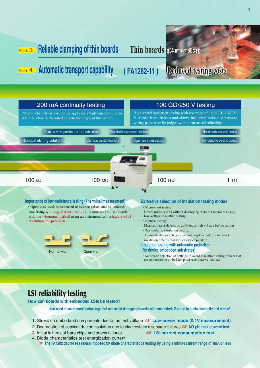
3
Reliable clamping of thin boards
Point
4
Automatic transport capability
Thin boards
( FA1282-11 )
(0.2 mm and less)
Reduced testing costs
200 mA continuity testing
100 GΩ/250 V testing
Pattern reliability is assured by applying a high current of up to
200 mA, close to the rated current for a typical fine pattern.
High-speed insulation testing with coverage of up to 100 GΩ/250
V detects latent defects and allows insulation resistance between
wiring patterns to be judged with unsurpassed reliability.
Conductive impurities such as suboxides
Residual etching solution
Dust that has absorbed moisture
Surface contamination
100 kΩ
100 MΩ
Importance of low-resistance testing (4-terminal measurement)
• Open vias result in increased resistance values and inductance,
interfering with signal transmission. It is necessary to test boards
with the 4-terminal method using an instrument with a high level of
resolution and precision
Normal via
Open via
Non-defective organic product
Impurities in insulators
Non-defective ceramic product
100 GΩ
1 TΩ
Extensive selection of insulation testing modes
•Micro-short testing:
Detect micro-shorts without destroying them in the process using
low-voltage insulation testing
•Impulse testing:
Manifest latent defects by applying a high voltage before testing
•Dual-polarity insulation testing:
Automatically switch positive and negative polarity to detect
insulation defects that are polarity-dependent.
Insulation testing with automatic protection
(for device embedded substrates)
•Automatic selection of settings to avoid insulation testing of nets that
are connected to embedded passive and active devices
LSI reliability testing
How can boards with embedded LSIs be tested?
You need measurement technology that can avoid damaging boards with embedded LSIs due to static electricity and stress!
1. Stress on embedded components due to the test voltage
Low-power mode (0.1V measurement)
2. Degradation of semiconductor insulation due to electrostatic discharge failures
I/O pin leak current test
3. Initial failures of bare chips and stress failures
LSI current consumption test
4. Diode characteristics test energization current
The FA1282 decreases stress imposed by diode characteristics testing by using a minute current range of 1mA or less
Model
FLYING PROBE TESTER FA1282-01
FLYING PROBE TESTER FA1282-11
Mechanism
Without transport
capability
With transport
capability
No. of arms
Measurement Unit
Maximum resolution
Air supply
Air consumption
Operating
environment
Dimensions and
weight
Standard
accessories
Board clamping
: 40.00 μΩ to 100.0 MΩ
: 10.00 fF to 40.00 mF
: 10.00 μH to 100.0 mH
: 0.000 V to 25.00 V
: 200.0 Ω to 100 GΩ
: 200.0 Ω to 10.00 MΩ
: 200.0 Ω to 25.00 GΩ
: 400.0 mΩ to 400.0 kΩ
: 100.0 nA to 10.00 mA
: 0.000 V to 25.00 V
: 0.000 V to 25.00 V
: 0.000 V to 25.00 V
: 400mΩ to 1.000kΩ
: 4.000Ω to 4.000MΩ
: 400.0mΩ to 40.00kΩ
: 0.040 V to 25.00 V
400 × 324 (mm)
X , Y : ±3μm
X , Y : 1.00μm
Z
: 5.00μm
Chucks on 2 sides of board (*Chucks are not used at center of board.)
Z upper : 12mm from board reference surface (max.), including board thickness
Z lower : 12mm from board reference surface (max.)
Probe clearance
300,000 (max.)
Display
17” liquid crystal display (LCD)
Options
Measurement
FA1937-50 Embedded Device Board Test Unit
FA1938-22 Micro ARC Detection Unit
AC-LowPower(measurement voltage: 0.1 V)
LSI testing
MLCC measurement
Impedance testing
Detects arcs of 1 μs or greater
(Standard specifications, 1 ms or greater)
Probing precision
FA1971-01 Precision Probing Function
Camera, lens, and illumination
FA1945-68 Coaxial EPI-Illumination Unit
Set of cameras for all arms
FA1945-69 Oblique Illumination Unit
Set of cameras for all arms
1947-61
1.2 Power Lens Unit
Set of cameras for all arms
1139-09
1281 Data Composition Software
1139-55
FL-LINK6 Software
1139-60
EPA-Line Link Software
1139-61
SIM-Line Link Software
1391
EPA-Line Test Data Generation System
-99.9% to +999.9% or absolute value
1392
SIM-Line Test Data Generation System
2 points/step
1741
Fly-Line Inspection Data Creation System
1330-03
Measurement Section Calibration Unit
R:Up to 500 MΩ; C, L: All
1330-06
Measurement Section Calibration Unit
1 GΩ to 100 GΩ
: 100mV / 400mV / 12 V (3 ranges)
: 1 to 250 V (variable in 1 V steps)
: 200 nA to 200 mA (13 ranges)
: 0.1m to 25m A (variable in 0.1 mA steps)
: 1 Vrms / 10 Vpeak (2 ranges)
: 80m / 125m / 400m / 4 / 25 V f.s. (5 ranges)
: 40m / 400m / 4 / 40 / 250 V (5 ranges)
: 100 nA to 25 mA f.s. (7 ranges)
: 10 nA to 100 mA (8 ranges)
: 10μ / 100μ / 1m A /10mArms (4 ranges)
: 1μ / 10μ / 100μ A peak (3 ranges)
General Specifications
Power supply
0.1 to 2.5 (mm)
100 steps/second
(*0.15 mm movements, 4-arm simultaneous probing, capacitance measurement)
Resistance
Capacitance
Inductance
Diode VZ measurement
Insulation measurement
Capacitor insulation measurement
High-voltage resistance measurement
High-voltage short measurement
Leak current measurement
Tests
Zener diode VZ measurement
•
Measurement ranges Digital transistor measurement
Photocoupler measurement
Continuity measurement
Open measurement
Short measurement
DC voltage measurement
Discharge function
Simple visual presence test
Simple visual alignment measurement
DC constant voltage DC measurement mode
DC constant voltage Insulation measurement mode
DC constant current DC measurement mode
DC constant current Insulation measurement mode
AC constant voltage
DC voltmeter
DC measurement mode
Test signals
DC voltmeter
Insulation measurement mode
DC ammeter
DC measurement mode
DC ammeter
Insulation measurement mode
AC ammeter
: (at 1 Vrms)
(at 10 Vpeak)
Judgment range
Guarding
50 (W) × 50 (D) to 400 (W) × 330 (D) mm
200VAC ±10%(single-phase) 50/60Hz
(Supply voltages of 220 V, 230 V, and 240 V AC can also be specified at the time of order.)
Max. power consumption 5 kVA
Air pressure (primary) 0.5 to 0.99 MPa (dry air)
Set pressure (secondary) 0.5 ±0.1 MPa
Test data creation
Other
FA1350-05 Offset Board
FA1395
Double-sided, thickness =1 mm
Recovery disc
FA1942-31 Board Loading Rails
Max. 0.3 Nl/min (ANR)
Temperature: 23°C ±10°C
Humidity: 75% RH or less (non-condensing)
Atmosphere: Avoid use in environments characterized by excessive dust,
vibration, or corrosive gasses.
Floor strength: At least 500 kg/m2
1944-03
Extension I/O Board
1941-80
Stamp Marking With Oil Paint
FA1282 external dimensions (reference chart)
Weight
Approx. 1,100 kg
Dimensions: 1,350 (W) × 1,206 (H) × 1,240 (D) mm
(*Excluding signal tower and other protruding parts.)
Weight: 1,100 kg
Scratch Sheet1134-02, Offset BoardFA1350-05, Instruction Manual (with warranty card), Grease,
Grease gun, Hexagonal wrench (2.5) (for replacing probes),
Double Open-end Spanner (5.5x7) (for use with front cosmetic panel), Nut Driver (7) (for use with
front cosmetic panel), Leveling jack 4, Anti-slip pad4, LCD display (17-inch),
Thermal mini-printer (including 1 roll of paper), Printer cable,
Power cord (terminating in bare wires; 3meters in length), Spare fuse (for internal 5 V and
24 V use), Computer accessories (computer manuals, etc.), Setup disk ,
Keyboard (included with computer), Mouse (included with computer), Mouse pad,
Probes × 4 (as selected) (Please select from 1172-66, 1172-68, 1172-81 and 1172-82 at the time of order.)
1626
No. of test steps
Compatible board size
Compatible board thickness
Probable area
Repeatability
1206
Test speed
4 (upper: 2; lower: 2)
1350
1240
Note: Company names and Product names appearing in this catalog are trademarks or registered trademarks of various companies.
HIOKI (Shanghai) SALES & TRADING CO., LTD.
TEL +86-21-63910090 FAX +86-21-63910360
http://www.hioki.cn / E-mail: info@hioki.com.cn
РАДАР - ОФИЦИАЛЬНЫЙ ДИЛЕР HIOKI
HIOKI INDIA PRIVATE LIMITED
TEL +91-124-6590210
HEADQUARTERS
E-mail: hioki@hioki.in
81 Koizumi, Ueda, Nagano, 386-1192, Japan
TEL +81-268-28-0562 FAX +81-268-28-0568
HIOKI SINGAPORE PTE. LTD.
http://www.hioki.com / E-mail: os-com@hioki.co.jp TEL +65-6634-7677 FAX +65-6634-7477
E-mail: info-sg@hioki.com.sg
HIOKI USA CORPORATION
HIOKI KOREA CO., LTD.
TEL +1-609-409-9109 FAX +1-609-409-9108
TEL +82-42-936-1281 FAX +82-42-936-1284
http://www.hiokiusa.com / E-mail: hioki@hiokiusa.com E-mail: info-kr@hioki.co.jp
All information correct as of June 30, 2015. All specifications are subject to change without notice.
РОССИЯ, 198152, Санкт-Петербург
Краснопутиловская ул., д.25
Тел./факс +7 (812) 600-48-89
Тел.: +7 (812) 375-32-44
www.radar1.ru
FA1282E1-56E
Printed in Japan
info@radar1.ru
Download HIOKI FA1282 ENG
HIOKI_FA1282_ENG.pdf (PDF, 2.54 MB)
Download PDF
Share this file on social networks
Link to this page
Permanent link
Use the permanent link to the download page to share your document on Facebook, Twitter, LinkedIn, or directly with a contact by e-Mail, Messenger, Whatsapp, Line..
Short link
Use the short link to share your document on Twitter or by text message (SMS)
HTML Code
Copy the following HTML code to share your document on a Website or Blog
QR Code to this page

This file has been shared publicly by a user of PDF Archive.
Document ID: 0000326541.