HIOKI IM3570 ENG (PDF)
File information
Title: IMPEDANCE ANALYZER IM3570
Author: HIOKI
This PDF 1.7 document has been generated by Adobe InDesign CS5.5_J (7.5.3) / Adobe PDF Library 9.9, and has been sent on pdf-archive.com on 25/12/2015 at 07:45, from IP address 5.18.x.x.
The current document download page has been viewed 762 times.
File size: 3.16 MB (8 pages).
Privacy: public file
File preview
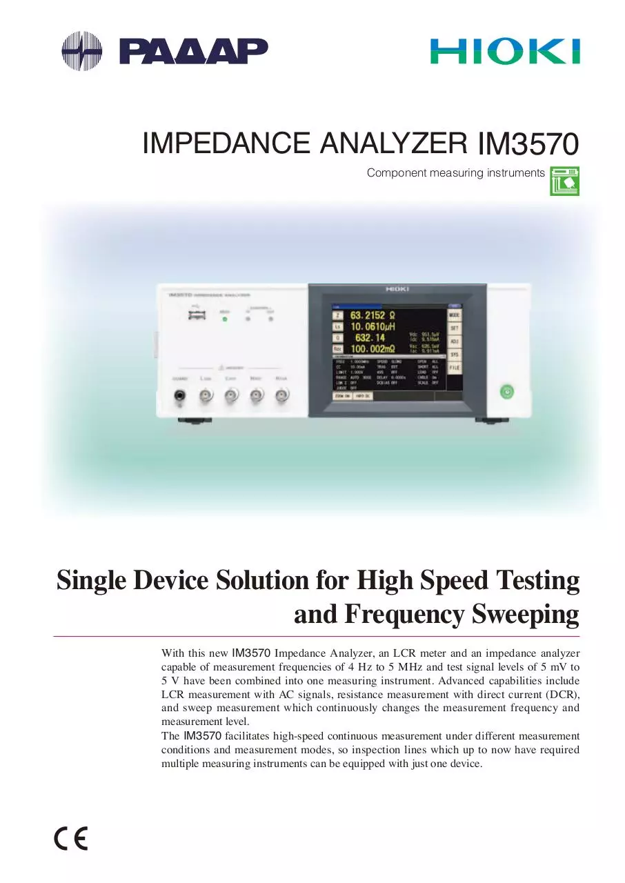
IMPEDANCE ANALYZER IM3570
Component measuring instruments
Single Device Solution for High Speed Testing
and Frequency Sweeping
With this new IM3570 Impedance Analyzer, an LCR meter and an impedance analyzer
capable of measurement frequencies of 4 Hz to 5 MHz and test signal levels of 5 mV to
5 V have been combined into one measuring instrument. Advanced capabilities include
LCR measurement with AC signals, resistance measurement with direct current (DCR),
and sweep measurement which continuously changes the measurement frequency and
measurement level.
The IM3570 facilitates high-speed continuous measurement under different measurement
conditions and measurement modes, so inspection lines which up to now have required
multiple measuring instruments can be equipped with just one device.
2
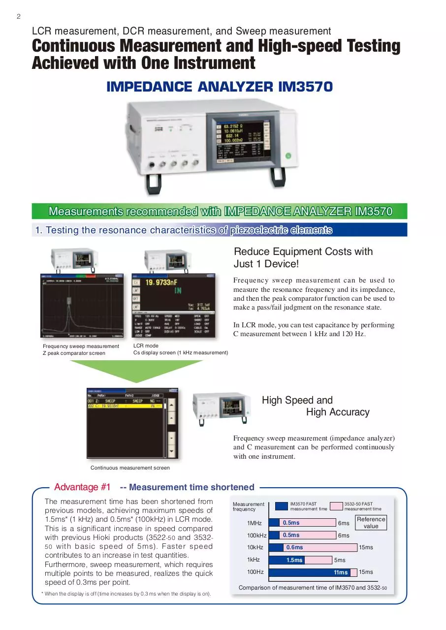
LCR measurement, DCR measurement, and Sweep measurement
Continuous Measurement and High-speed Testing
Achieved with One Instrument
IMPEDANCE ANALYZER IM3570
Measurements recommended with IMPEDANCE ANALYZER IM3570
1. Testing the resonance characteristics of piezoelectric elements
Reduce Equipment Costs with
Just 1 Device!
Frequency sweep measurement can be used to
measure the resonance frequency and its impedance,
and then the peak comparator function can be used to
make a pass/fail judgment on the resonance state.
In LCR mode, you can test capacitance by performing
C measurement between 1 kHz and 120 Hz.
Frequency sweep measurement
Z peak comparator screen
LCR mode
Cs display screen (1 kHz measurement)
High Speed and
High Accuracy
Frequency sweep measurement (impedance analyzer)
and C measurement can be performed continuously
with one instrument.
Continuous measurement screen
Advantage #1 -- Measurement time shortened
The measurement time has been shortened from
previous models, achieving maximum speeds of
1.5ms* (1 kHz) and 0.5ms* (100kHz) in LCR mode.
This is a significant increase in speed compared
with previous Hioki products (3522-50 and 35325 0 with basic speed of 5ms). Faster speed
contributes to an increase in test quantities.
Furthermore, sweep measurement, which requires
multiple points to be measured, realizes the quick
speed of 0.3ms per point.
* When the display is off (time increases by 0.3 ms when the display is on).
Measurement
frequency
IM3570 FAST
measurement time
3532-50 FAST
measurement time
1MHz
0.5ms
6ms
100kHz
0.5ms
6ms
10kHz
0.6ms
1kHz
1.5ms
100Hz
Reference
value
15ms
5ms
11ms
15ms
Comparison of measurement time of IM3570 and 3532-50
Perfect Impedance Analyzer for Production Lines
2. C-D and low ESR measurement of functional polymer capacitors
LCR mode
Cs and D display screen (120 Hz measurement)
LCR mode
Rs display screen (100 kHz measurement)
Continuous measurement screen
Make continuous tests for different measurement
items under different measurement conditions
(frequency, level, and mode).
C-D (120 Hz) and low ESR (100 kHz) measurement
can be performed for functional polymer capacitors.
Advantage #2
-- Low-impedance measurement accuracy improved
Repeat accuracy of IM3570 when measuring 1 mΩ 100 times
Measurement
speed
SLOW2
SLOW
Reference value
0.03%
0.08%, 5.9ms
0.12%, 1.7ms
MID
FAST
44.5ms
0.5ms
0.54%
Variation [%] and measurement time [ms]
A one-digit improvement in repeat accuracy during
low-impedance measurement has been achieved
compared with previous Hioki products.
For example, when the condition is 1 mΩ (1V, 100
kHz) and the measurement speed is MED, stable
measurement with a repeat accuracy (variation)* of
0.12% is possible, making this instrument suitable for
100 kHz ESR measurement.
* Repeat accuracy (variation) is calculated based on the difference
between the maximum and minimum values.
3. DCR and L-Q measurement of inductors (coils and transformers)
L/Q display screen
(1 kHz, 1 mA constant current measurement)
DCR display screen
(DC measurement)
L/Q/ DCR continuous measurement screen
L/Q (1 kHz, 1 mA constant current measurement)
and DCR (DC measurement) display screen
The instrument can continuously measure L-Q
(1 kHz, 1mA constant current) and DCR, and
display the numerical values on the same screen.
Cur rent dependent elements such as coils
incorporating cores for which the inductance
value varies depending on the applied current
can be measured with a constant current (CC).
Since there is a one-digit improvement in repeat
accuracy during low impedance measurement
compa red wit h previous products, st able
measurement of DCR can be expected.
Advantage #3
By improving the measurement accuracy of θ compared with previous Hioki products, measurement with
an absolute accuracy and repeat accuracy of one-digit better than before can be performed for high Q and
Rs values for which θ is in the vicinity of 90°.
The measurement frequency of a coil differs
dep end i ng on t he appl icat ion. T he wide
measurement range of 4 Hz to 5 MHz facilitates the
measurement of various coils.
Constant current sweep measurement enables a
current characteristic graph to be displayed for
current dependent elements.
Frequency sweep measurement
Z-θ measurement screen
CC value sweep measurement
Ls measurement screen
3
4
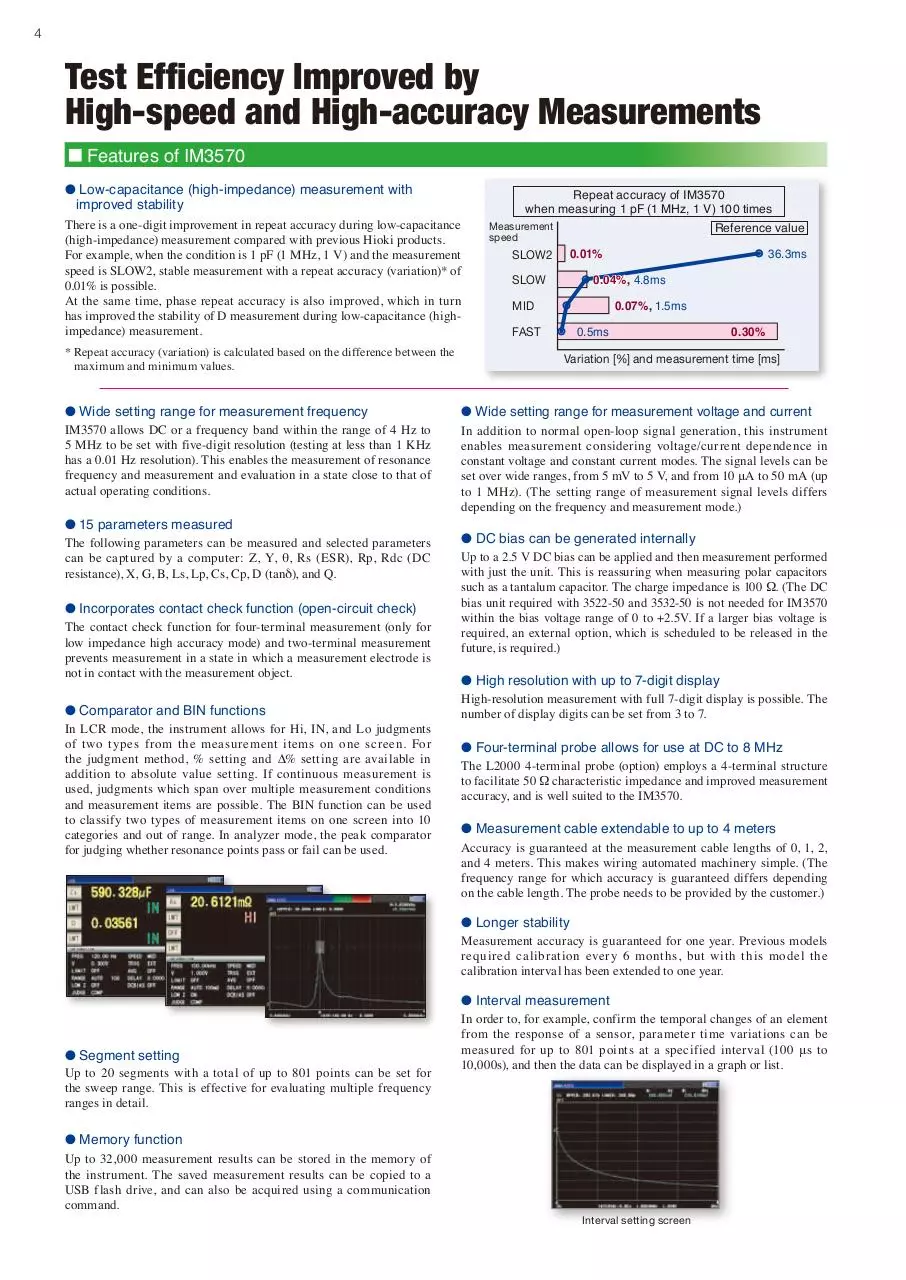
Test Efficiency Improved by
High-speed and High-accuracy Measurements
Features of IM3570
● Low-capacitance (high-impedance) measurement with
improved stability
There is a one-digit improvement in repeat accuracy during low-capacitance
(high-impedance) measurement compared with previous Hioki products.
For example, when the condition is 1 pF (1 MHz, 1 V) and the measurement
speed is SLOW2, stable measurement with a repeat accuracy (variation)* of
0.01% is possible.
At the same time, phase repeat accuracy is also improved, which in turn
has improved the stability of D measurement during low-capacitance (highimpedance) measurement.
* Repeat accuracy (variation) is calculated based on the difference between the
maximum and minimum values.
● Wide setting range for measurement frequency
IM3570 allows DC or a frequency band within the range of 4 Hz to
5 MHz to be set with five-digit resolution (testing at less than 1 KHz
has a 0.01 Hz resolution). This enables the measurement of resonance
frequency and measurement and evaluation in a state close to that of
actual operating conditions.
● 15 parameters measured
The following parameters can be measured and selected parameters
can be captured by a computer: Z, Y, θ, Rs (ESR), Rp, Rdc (DC
resistance), X, G, B, Ls, Lp, Cs, Cp, D (tanδ), and Q.
● Incorporates contact check function (open-circuit check)
The contact check function for four-terminal measurement (only for
low impedance high accuracy mode) and two-terminal measurement
prevents measurement in a state in which a measurement electrode is
not in contact with the measurement object.
● Comparator and BIN functions
In LCR mode, the instrument allows for Hi, IN, and Lo judgments
of two types from the measurement items on one screen. For
the judgment method, % setting and ∆% setting are available in
addition to absolute value setting. If continuous measurement is
used, judgments which span over multiple measurement conditions
and measurement items are possible. The BIN function can be used
to classify two types of measurement items on one screen into 10
categories and out of range. In analyzer mode, the peak comparator
for judging whether resonance points pass or fail can be used.
Repeat accuracy of IM3570
when measuring 1 pF (1 MHz, 1 V) 100 times
Measurement
speed
SLOW2
Reference value
0.01%
36.3ms
0.04%, 4.8ms
SLOW
0.07%, 1.5ms
MID
FAST
0.5ms
0.30%
Variation [%] and measurement time [ms]
● Wide setting range for measurement voltage and current
In addition to normal open-loop signal generation, this instrument
enables measurement considering voltage/current dependence in
constant voltage and constant current modes. The signal levels can be
set over wide ranges, from 5 mV to 5 V, and from 10 μA to 50 mA (up
to 1 MHz). (The setting range of measurement signal levels differs
depending on the frequency and measurement mode.)
● DC bias can be generated internally
Up to a 2.5 V DC bias can be applied and then measurement performed
with just the unit. This is reassuring when measuring polar capacitors
such as a tantalum capacitor. The charge impedance is 100 Ω. (The DC
bias unit required with 3522-50 and 3532-50 is not needed for IM3570
within the bias voltage range of 0 to +2.5V. If a larger bias voltage is
required, an external option, which is scheduled to be released in the
future, is required.)
● High resolution with up to 7-digit display
High-resolution measurement with full 7-digit display is possible. The
number of display digits can be set from 3 to 7.
● Four-terminal probe allows for use at DC to 8 MHz
The L2000 4-terminal probe (option) employs a 4-terminal structure
to facilitate 50 Ω characteristic impedance and improved measurement
accuracy, and is well suited to the IM3570.
● Measurement cable extendable to up to 4 meters
Accuracy is guaranteed at the measurement cable lengths of 0, 1, 2,
and 4 meters. This makes wiring automated machinery simple. (The
frequency range for which accuracy is guaranteed differs depending
on the cable length. The probe needs to be provided by the customer.)
● Longer stability
Measurement accuracy is guaranteed for one year. Previous models
required calibration every 6 months, but with this model the
calibration interval has been extended to one year.
● Interval measurement
● Segment setting
Up to 20 segments with a total of up to 801 points can be set for
the sweep range. This is effective for evaluating multiple frequency
ranges in detail.
In order to, for example, confirm the temporal changes of an element
from the response of a sensor, parameter time variations can be
measured for up to 801 points at a specified interval (100 μs to
10,000s), and then the data can be displayed in a graph or list.
● Memory function
Up to 32,000 measurement results can be stored in the memory of
the instrument. The saved measurement results can be copied to a
USB flash drive, and can also be acquired using a communication
command.
Interval setting screen
5
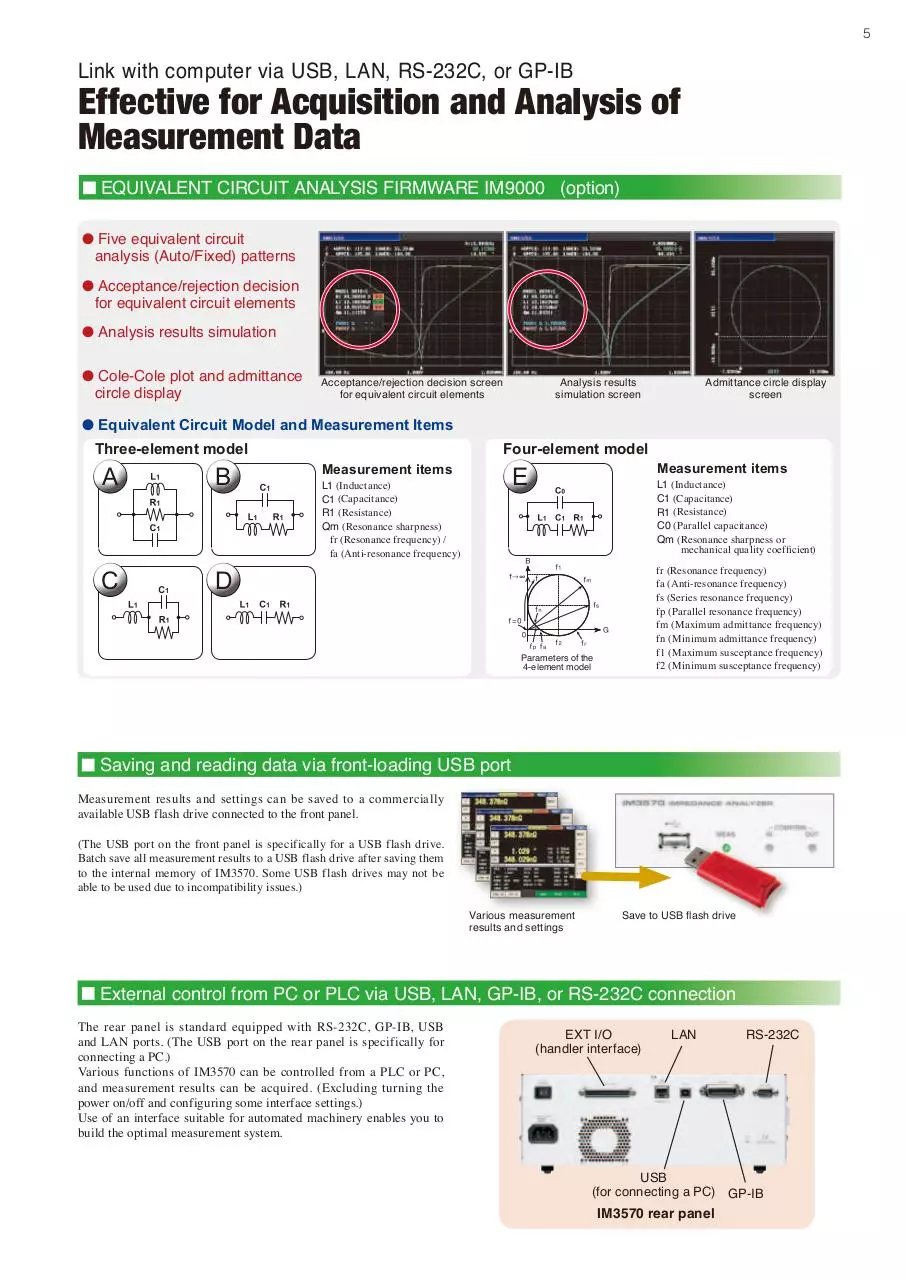
Link with computer via USB, LAN, RS-232C, or GP-IB
Effective for Acquisition and Analysis of
Measurement Data
EQUIVALENT CIRCUIT ANALYSIS FIRMWARE IM9000 (option)
l Five equivalent circuit
analysis (Auto/Fixed) patterns
l Acceptance/rejection decision
for equivalent circuit elements
l Analysis results simulation
l Cole-Cole plot and admittance
circle display
Acceptance/rejection decision screen
for equivalent circuit elements
Analysis results
simulation screen
Admittance circle display
screen
l Equivalent Circuit Model and Measurement Items
Three-element model
A
B
C
D
Four-element model
Measurement items
E
L1 (Inductance)
C1 (Capacitance)
R1 (Resistance)
Qm (Resonance sharpness)
fr (Resonance frequency) /
fa (Anti-resonance frequency)
Measurement items
L1 (Inductance)
C1 (Capacitance)
R1 (Resistance)
C0 (Parallel capacitance)
Qm (Resonance sharpness or
mechanical quality coefficient)
fr (Resonance frequency)
fa (Anti-resonance frequency)
fs (Series resonance frequency)
fp (Parallel resonance frequency)
fm (Maximum admittance frequency)
fn (Minimum admittance frequency)
f1 (Maximum susceptance frequency)
f2 (Minimum susceptance frequency)
Parameters of the
4-element model
Saving and reading data via front-loading USB port
Measurement results and settings can be saved to a commercially
available USB flash drive connected to the front panel.
(The USB port on the front panel is specifically for a USB flash drive.
Batch save all measurement results to a USB flash drive after saving them
to the internal memory of IM3570. Some USB flash drives may not be
able to be used due to incompatibility issues.)
Various measurement
results and settings
Save to USB flash drive
External control from PC or PLC via USB, LAN, GP-IB, or RS-232C connection
The rear panel is standard equipped with RS-232C, GP-IB, USB
and LAN ports. (The USB port on the rear panel is specifically for
connecting a PC.)
Various functions of IM3570 can be controlled from a PLC or PC,
and measurement results can be acquired. (Excluding turning the
power on/off and configuring some interface settings.)
Use of an interface suitable for automated machinery enables you to
build the optimal measurement system.
EXT I/O
(handler interface)
LAN
USB
(for connecting a PC)
IM3570 rear panel
RS-232C
GP-IB
6
EXT I/O
● Handler (EXT I/O) interface
The handler (EXT I/O) interface enables output of an end of measurement signal and measurement result signal, and input of signals such as a measurement trigger
signal to control the measuring instrument. Each of the signal lines is isolated from the control circuit, and the structure is designed to protect against noise.
Example of representative EXT I/O timing
t0: Minimum time for trigger signal: 0.3 ms or longer *1
t1: Delay setting time from comparator and BIN judgment results
to EOM (LOW): 0.04 ms or longer *1
t2: Minimum time from end of measurement to next trigger: 0.4 ms *1
t3: Time from trigger to response by circuit: 0.7 ms *1
t4: Minimum chuck time for which chuck can be switched with
INDEX (LOW): 0.3 ms *1
t5: Measurement time: 0.5 ms *1
*1: When the measurement speed is FAST and the range is HOLD.
Connectors
Connectors to use (unit side) : 37-pin D-SUB female connector with #4-40 inch screws
Compliant connectors
: DC-37P-ULR (solder type) and DCSP-JB37PR
(insulation-displacement type)
For information on where to obtain connectors,
consult your nearest HIOKI distributor.
IM3570 specifications
(Accuracy guaranteed for 1 year, Post-adjustment accuracy guaranteed for 1 year)
Measurement
modes
Measurement
parameters
Measurement
range
Display range
LCR mode: Measurement with single condition
Analyzer mode:
Sweeps with measurement frequency and
measurement level
(Measurement points: 1 to 801,
Measurement method: normal sweep or segment sweep,
Display: List display or graph display)
Continuous measurement mode:
Measures under saved conditions continuously
(maximum of 32 sets)
Z
Y
θ
Rs(ESR)
Rp
Rdc
X
G
B
Cs
Cp
Ls
Lp
D(tanδ)
Q
Impedance
Admittance
Phase angle
Series-equivalent resistance = ESR
Parallel-equivalent resistance
DC resistance
Reactance
Conductance
Susceptance
Series-equivalent static capacitance
Parallel-equivalent static capacitance
Series-equivalent inductance
Parallel-equivalent inductance
Loss coefficient = tan δ (δ= delta)
Q factor (Q = 1/D)
100 mΩ to 100 MΩ, 12 ranges
(All parameters are determined according to Z )
Z, Y, Rs, Rp, Rdc, X, G, B, Ls, Lp, Cs, Cp :
±(0.000000 [unit] to 9.999999G [unit]
Absolute value display for Z and Y only
θ : ±(0.000° to 999.999°)
D : ±(0.000000 to 9.999999)
Q : ±(0.00 to 99999.99)
Δ % : ±(0.0000% to 999.9999%)
Basic accuracy Z : ±0.08%rdg. θ: ±0.05°
Measurement frequency 4Hz to 5MHz (10 mHz to 100 Hz steps)
Measurement
signal level
Normal mode:
V mode/CV mode: 5 mV to 5 Vrms (up to 1 MHz),
10 mV to 1 Vrms (1 MHz to 5 MHz), 1 mVrms steps
CC mode: 10 μA to 50 mArms (up to 1 MHz),
10 μA to 10 mArms (1 MHz to 5 MHz), 10 μArms steps
Low impedance high accuracy mode:
V mode/CV mode:
5 mV to 1 Vrms (up to 100 kHz), 1 mVrms steps
CC mode:10 μA to 100 mArms (100 mΩ and 1Ω
ranges of up to 100 kHz), 10 μArms steps
Output
impedance
Display
No. of display
digits setting
Measurement time
Measurement speed
Normal mode: 100 Ω
Low impedance high accuracy mode: 10 Ω
5.7-inch color TFT, display can be set to ON/OFF
The number of display digits can be set from 3 to 7
(initial value: 6 digits)
0.5 ms (100 kHz, FAST, display OFF, representative value)
FAST/MED/SLOW/SLOW2
DC bias
measurement
Normal mode: 0 VDC to 2.50 VDC (10 mV steps)
Low impedance high accuracy mode:
0 VDC to 1.00 VDC (10 mV steps)
DC resistance
measurement
Normal mode
Measurement signal level: 100 mVDC to 2.5 VDC (10 mV steps)
Low impedance high accuracy mode
Measurement signal level: 100 mVDC to 1.00 VDC (10 mV steps)
Comparator
BIN measurement
Compensation
Residual charge
protection function
Trigger synchronous
output function
Averaging
Interval measurement
Panel loading/saving
Memory function
Interfaces
Operating temperature
and humidity ranges
Storage temperature
and humidity ranges
Power supply
Dimensions and weight
Accessory
LCR mode: Hi/IN/Lo for first and third items
Analyzer mode:
Area judgment (Hi/IN/Lo for each point)
Peak judgment (Hi/IN/Lo for local maximum and local
minimum frequency and absolute values)
10 classifications and out of range for 2 items
Open/short/load/cable length of 0 and 1 m/correlation
compensation
V= √ 10/C
(C: Capacitance [F] of test sample, V = max. 400 V)
Applies a measurement signal during analog measurement
only
1 to 256
100 μs to 10,000 s, max. 801 points
LCR mode: 30; Analyzer mode: 2; Compensation value: 128
Stores 32,000 data items to the memory of the instrument
EXT I/O (handler), RS-232C, GP-IB, USB (Hi-Speed/FullSpeed), USB flash drive, LAN (10BASE-T/100BASE-TX)
0°C to 40°C, 80% RH or less, no condensation
-10°C to 50°C, 80% RH or less, no condensation
90 to 264 V AC, 50/60 Hz, 150 VA max.
Approx. 330 (W) x 119 (H) x 307 (D), approx. 5.8 kg
Power Cord x 1, Instruction Manual x 1, Communication
Instruction Manual (CD) x 1
7
IM3570 measurement accuracy
Conditions
The measurement accuracy is calculated based on the following equation.
Temperature and humidity ranges: 23℃ ± 5℃, 80% RH or less (no condensation),
at least 60 minutes after power turned on, after performing open and short compensation
Basic accuracy (Z, θ)
calculation expression
Measurement accuracy = Basic accuracy × C × D × E × F × G
[C: Level coefficient] V: Setting value (corresponds to when V mode) [V]
0.1
0.005V to 0.999V : 1 +
(For measurements other than DCR, at 30kΩ range or below)
V
0.3 (All DCR ranges, and 100kΩ range and above for
1+
V measurements other than DCR)
1V to 5V : 1
In the 1 kΩ range and above and 300 Ω range and below, the
calculation expression of basic accuracy differs as shown below.
For details, refer to the following calculation examples.
Top A: Basic accuracy of Z (± % rdg.)
B is the coefficient for the impedance of the sample
Bottom A: Basic accuracy of θ (± % deg.)
B is the coefficient for the impedance of the sample
A is the accuracy of R when DC (± % rdg.)
B is the coefficient for the resistance of the sample
1 kΩ range and above:
Accuracy = A + B ×
[D: Measurement speed coefficient]
FAST : 8, MED : 4, SLOW : 2, SLOW2: 1
10 × Zx
-1
Range
[E: Measurement cable length coefficient] fm: Measurement frequency [kHz]
0 m : 1 (DC to 5MHz), 1 m : 1.5 (DC to 5MHz),
2 m : 2 × 1+ fm (DC to 100kHz), 4 m : 4 × 1+ fm (DC to 10kHz)
100
100
300 Ω range and below:
Range
-1
Accuracy = A + B ×
Zx
(
Zx is the actual impedance measurement
value (Z) of the sample.
Guaranteed
accuracy range
DC
10MΩ 800kΩ to 100MΩ
4 Hz to 99.9 Hz
A=6 B=5
A=5 B=3
A=4 B=6
A=0.5 B=0.3
A=0.2 B=0.1
80kΩ to 10MΩ
100kΩ 24kΩ to 1MΩ
A=0.1 B=0.01
30kΩ
8kΩ to 300kΩ
A=0.1 B=0.01
10kΩ
2.4kΩ to 100kΩ
A=0.1 B=0.01
3kΩ
800Ω to 30kΩ
A=0.1 B=0.01
1kΩ
240Ω to 10kΩ
A=0.1 B=0.01
A=0.1 B=0.02
300Ω
8Ω to 300Ω
10Ω
800mΩ to 10Ω
A=0.2 B=0.15
1Ω
80mΩ to 1Ω
A=0.3 B=0.3
100mΩ 1mΩ to 100mΩ
A=3 B=2
A=0.8 B=1
A=0.8 B=0.5
A=0.4 B=0.08
A=0.3 B=0.08
A=0.3 B=0.01
A=0.3 B=0.01
A=0.3 B=0.01
A=0.3 B=0.01
A=0.3 B=0.01
A=0.3 B=0.01
A=0.3 B=0.02
A=0.2 B=0.01
A=0.3 B=0.02
A=0.2 B=0.01
A=0.4 B=0.02
A=0.2 B=0.01
A=0.5 B=0.2
A=0.3 B=0.1
A=2 B=1
A=1 B=0.6
A=10 B=10
A=6 B=6
100 Hz to 999.99 Hz
A=3 B=2
A=2 B=2
A=0.5 B=0.3
A=0.4 B=0.2
A=0.3 B=0.05
A=0.2 B=0.02
A=0.2 B=0.01
A=0.1 B=0.01
A=0.2 B=0.005
A=0.1 B=0.003
A=0.2 B=0.01
A=0.1 B=0.005
A=0.2 B=0.005
A=0.1 B=0.002
A=0.2 B=0.01
A=0.1 B=0.005
A=0.3 B=0.02
A=0.15 B=0.01
A=0.4 B=0.05
A=0.3 B=0.03
A=0.6 B=0.3
A=0.5 B=0.2
A=3 B=3
A=2 B=2
● Method of determining basic accuracy
• Calculate the basic accuracy from the sample impedance, measurement
range, and measurement frequency and the corresponding basic accuracy
A and coefficient B from the table above.
• The calculation expression to use differs for each of the 1 kΩ range and
above and 300 Ω range and below.
• For C and L, obtain basic accuracy A and coefficient B by determining the
measurement range from the actual measurement value of impedance or the
approximate impedance value calculated with the following expression.
Zx (Ω)
)
(
)
(
)
[G: Temperature coefficient] t: Operating temperature
When t is 18℃ to 28℃ : 1, When t is 0℃ to 18℃ or 28℃ to 40℃ : 1+ 0.1 × t-23
100MΩ 8MΩ to 200MΩ
1MΩ
(
[F: DC bias coefficient] VAC : AC signal voltage setting value [V]
DC bias setting OFF : 1
10Ω range or below,
DC bias setting ON : 2 × 1+ 0.1 , 4 × 1+ 0.1 (At
VAC
VAC minimum 100.01 kHz.)
Basic accuracy
Range
)
ωL (H) (θ 90º)
1
(θ -90º)
ωC (F)
R (Ω) (θ 0º) (ω: 2 x π x Measurement frequency [Hz])
1 kHz to 10 kHz
A=3 B=2
A=2 B=2
10.01 kHz to 100 kHz 100.1 kHz to 1 MHz 1.001 MHz to 5 MHz
A=0.5 B=0.3
A=0.4 B=0.2
A=0.3 B=0.05
A=0.2 B=0.02
A=0.15 B=0.01
A=0.1 B=0.01
A=0.12 B=0.005
A=0.08 B=0.003
A=0.12 B=0.005
A=0.08 B=0.002
A=0.12 B=0.005
A=0.08 B=0.002
A=0.1 B=0.005
A=0.08 B=0.002
A=0.08 B=0.02
A=0.05 B=0.01
A=0.3 B=0.05
A=0.15 B=0.03
A=0.4 B=0.3
A=0.25 B=0.2
A=3 B=3
A=2 B=1.5
A=8 B=4
A=3 B=2
* Set the accuracy to
A=1 B=0.7
A=1 B=0.2
A=0.3 B=0.08
A=0.3 B=0.08
A=0.25 B=0.04
A=0.2 B=0.02
A=0.25 B=0.01
A=0.15 B=0.005
A=0.2 B=0.02
A=0.08 B=0.02
A=0.2 B=0.005
A=0.08 B=0.005
A=0.2 B=0.01
A=0.08 B=0.01
A=0.2 B=0.02
A=0.08 B=0.02
A=0.3 B=0.05
A=0.15 B=0.03
A=0.4 B=0.3
A=0.25 B=0.2
A=2 B=2
A=2 B=1.5
A=3 B=2
A=3 B=1
A=1 B=0.5
A=1 B=0.5
A=0.4 B=0.3
A=0.3 B=0.3
A=0.4 B=0.05
A=0.3 B=0.03
A=0.3 B=0.03
A=0.2 B=0.05
A=0.3 B=0.01
A=0.15 B=0.01
A=0.3 B=0.01
A=0.15 B=0.01
A=0.3 B=0.03
A=0.15 B=0.02
A=0.4 B=0.2
A=0.3 B=0.1
A=1 B=1
A=0.7 B=0.5
A=4 B=3
A=3 B=4
( f [MHz] + 3 )
times
4
for 1.001 MHz or above.
* A=2 B=1
A=2 B=1
* A=2 B=0.5
A=2 B=0.3
* A=2 B=0.1
A=2 B=0.1
* A=1.5 B=0.2
A=1 B=0.2
* A=1.5 B=0.02
A=1 B=0.03
* A=1.5 B=0.01
A=1 B=0.01
* A=1.5 B=0.05
A=1 B=0.05
* A=2 B=1.5
A=2 B=1
* A=3 B=3
A=3 B=2
● Calculation example
Impedance Zx of sample: 500 Ω (actual measurement value)
Measurement conditions: When frequency 10 kHz and range 1 kΩ
Insert coefficient A = 0.1 and coefficient B = 0.005 for the Z basic
accuracy from the table above into the expression.
Z basic accuracy = 0.1 + 0.005 ×
10 × 500
-1 = 0.12 (± %rdg.)
103
Similarly, insert coefficient A = 0.08 and coefficient B = 0.002 for the θ
basic accuracy, as follows:
10 × 500
-1 = 0.088 (± deg.)
θ basic accuracy = 0.08 + 0.002 ×
103
Guaranteed accuracy range (measurement signal level)
The guaranteed accuracy range differs depending on the measurement frequency, measurement signal level, and measurement range.
Range
100MΩ
10MΩ
1MΩ
100kΩ
30kΩ,10kΩ,3kΩ,
1kΩ,300Ω,10Ω
1Ω
100mΩ
DC
1 V to 2.5 V
0.1 V to 2.5 V
0.1 V to 2.5 V *1
4 Hz to 99.9 Hz
100 Hz to 999.99 Hz
0.101 V to 5 V
0.050 V to 5 V
1 kHz to 10 kHz
0.005 V to 5 V
0.005 V to 5 V *2
0.101 V to 5 V *3
The above voltages are the voltage setting values correspond to when in V mode.
10.01 kHz to 100 kHz 100.1 kHz to 1 MHz 1.001 MHz to 5 MHz
0.501 V to 5 V
0.101 V to 5 V 0.501 V to 5 V
0.050 V to 5 V 0.101 V to 5 V 0.501 V to 1 V
0.050 V to 5 V 0.101 V to 1 V
0.050 V to 1 V
0.101 V to 5 V 0.501 V to 1 V
0.501 V to 5 V *3
*1 Guaranteed accuracy of 10 mΩ or above, *2 Guaranteed accuracy of 0.101 V to 5 V when DC bias, *3 Guaranteed accuracy of 10 mΩ or above and 1.001 V to 5 V when DC bias
Options
Probes and Test Fixtures for Lead Components
FOUR-TERMINAL
PROBE L2000
Cable length 1 m (3.28 ft), DC to 8 MHz,
Direct connection type, DC to 8 MHz,
characteristic impedance of 50 Ω, 4-terminal measurable conductor diameter: 0.3 to 2 mm
pair design, measurable conductor diameter: (0.01 to 0.08 in)
0.3 to 5 mm (0.01 to 0.20 in)
Direct connection type, DC to 8 MHz,
SMD sizes: 1 to 10 mm (0.04 to 0.39 in)
TEST FIXTURE
9261-10
FOUR-TERMINAL
PROBE 9140 -10
Cable length 1 m (3.28 ft), DC to 200 kHz,
characteristic impedance of 50 Ω, 4-terminal
pair design, measurable conductor diameter:
0.3 to 5 mm (0.01 to 0.20 in)
SMD TEST FIXTURE
9263
TEST FIXTURE
9262
Cable length 1 m (3.28 ft), DC to 8 MHz,
characteristic impedance of 50 Ω, 4-terminal
pair design, measurable conductor diameter:
0.3 to 1.5 mm (0.01 to 0.06 in)
SMD TEST FIXTURE
9677
Direct connection type, for SMDs with
electrodes on the side, DC to 120 MHz,
SMD sizes: 3.5 ±0.5 mm
SMD TEST FIXTURE
IM9100
SMD TEST FIXTURE
9699
Direct connection type, for SMDs with
electrode on the bottom, DC to 120 MHz,
SMD sizes: 1.0 to 4.0 mm wide, 1.5 mm or
less high
PINCHER PROBE
L2001
Four-terminal Probe for Electrochemical Measurement
FOUR-TERMINAL
PROBE 9500 -10
*Ships standard with one
set of IM9901
Cable length 730 mm (2.40 ft) , DC to 8 MHz,
characteristic impedance of 50 Ω, 4-terminal
pair design, 2-terminal electrode, tip electrode
spacing of 0.3 to approx. 6 mm (0.01 to approx.
0.24 in)
Cable length 1 m (3.28 ft), DC to 200 kHz, characteristic
impedance of 50 Ω, 4-terminal pair design, measurable
conductor diameter: 0.3 to 2 mm (0.01 to 0.08 in)
Compatible with 0402-, 0603-, and 1005-size
SMDs, 4-terminal electrode design; capable of
high-precision measurement
Options for L2001
Replaceable contact tips
CONTACT TIPS IM9901
Compatible chip sizes: 1608 to 5750 (JIS)
CONTACT TIPS IM9902
Compatible chip sizes: 0603 to 5750 (JIS)
EQUIVALENT CIRCUIT ANALYSIS FIRMWARE
DC Bias Unit
DC BIAS
VOLTAGE UNIT
9268 -10
Direct connection type, 40 Hz to 8 MHz,
maximum applied voltage: ±40 V DC
EQUIVALENT CIRCUIT
ANALYSIS FIRMWARE IM9000
DC BIAS
VOLTAGE UNIT
9269 -10
(Factory-installed option)
Direct connection type, 40 Hz to 2
MHz, maximum applied current 2 A DC
(maximum applied voltage: ±40 V DC)
*When using the 9268-10 or 9269-10, external constant-voltage and constant-current
sources are required.
The Equivalent Circuit Analysis Firmware IM9000 is an optional function for
the Impedance Analyzer IM3570. The IM9000 is not included in the standard
package. If you want to use the IM9000, specify the option upon purchase.
Customers who have purchased the Impedance Analyzer IM3570 can add the
Equivalent Circuit Analysis Firmware IM9000 function.
Please contact your Hioki distributor.
INTERFACE CABLE
IMPEDANCE ANALYZER IM3570
Accessories: Power cord, Instruction manual, CD-R [Communication
Instruction Manual])
Note: Test fixtures are not supplied with the instrument. Select optional test
fixtures or probes when ordering.
GP-IB CONNECTION CABLE 9151-02
2 m (6.56 ft)
l RS-232C Cable
As RS-232C cable, use an interlink (crossover) cable. The 9637 RS-232C
cable (9-pin to 9-pin, crossed cable) cannot be used for applications involving
the hardware flowcontrol.
Note: Company names and Product names appearing in this catalog are trademarks or registered trademarks of various companies.
HIOKI (Shanghai) SALES & TRADING CO., LTD.
TEL +86-21-63910090 FAX +86-21-63910360
http://www.hioki.cn / E-mail: info@hioki.com.cn
РАДАР - ОФИЦИАЛЬНЫЙ ДИЛЕР HIOKI
HIOKI INDIA PRIVATE LIMITED
TEL +91-124-6590210
HEADQUARTERS
E-mail: hioki@hioki.in
81 Koizumi, Ueda, Nagano, 386-1192, Japan
TEL +81-268-28-0562 FAX +81-268-28-0568
HIOKI SINGAPORE PTE. LTD.
http://www.hioki.com / E-mail: os-com@hioki.co.jp TEL +65-6634-7677 FAX +65-6634-7477
E-mail: info-sg@hioki.com.sg
HIOKI USA CORPORATION
HIOKI KOREA CO., LTD.
TEL +1-609-409-9109 FAX +1-609-409-9108
TEL +82-2-2183-8847 FAX +82-2-2183-3360
http://www.hiokiusa.com / E-mail: hioki@hiokiusa.com E-mail: info-kr@hioki.co.jp
All information correct as of Mar. 30, 2015. All specifications are subject to change without notice.
РОССИЯ, 198152, Санкт-Петербург
Краснопутиловская ул., д.25
Тел./факс +7 (812) 600-48-89
Тел.: +7 (812) 375-32-44
www.radar1.ru
IM3570E7-53E
Printed in Japan
info@radar1.ru
Download HIOKI IM3570 ENG
HIOKI_IM3570_ENG.pdf (PDF, 3.16 MB)
Download PDF
Share this file on social networks
Link to this page
Permanent link
Use the permanent link to the download page to share your document on Facebook, Twitter, LinkedIn, or directly with a contact by e-Mail, Messenger, Whatsapp, Line..
Short link
Use the short link to share your document on Twitter or by text message (SMS)
HTML Code
Copy the following HTML code to share your document on a Website or Blog
QR Code to this page

This file has been shared publicly by a user of PDF Archive.
Document ID: 0000326662.