HIOKI RM3542 ENG (PDF)
File information
Title: RESISTANCE HiTESTER RM3542
Author: HIOKI
This PDF 1.7 document has been generated by Adobe InDesign CS5.5_J (7.5.3) / Adobe PDF Library 9.9, and has been sent on pdf-archive.com on 25/12/2015 at 07:51, from IP address 5.18.x.x.
The current document download page has been viewed 792 times.
File size: 2.58 MB (8 pages).
Privacy: public file


File preview
RESISTANCE HiTESTER RM3542
Component Measuring Instruments
Measure in as little as 0.9 ms*
High-Speed Resistance Meters
Optimized for Automated Systems
The RM3542 and RM3542- 01 Resistance HiTESTERs employ the four-terminal
DC method to quickly and accurately measure the resistance of components such
as resistors and ferrite bead inductors. Both models include advanced contactcheck, comparator, and data export functions. The intuitive user interface and
superb noise immunity are ideal for use with taping machines and separators.
* including contact checking
2
Equipped with Contact Improver and contact check functions
Reliable Resistance Measurement, Ideal for Automated Systems
RESISTANCE HiTESTER
RM3542, RM3542-01
Features
High speed and accuracy maximize productivity
in automated systems.
Multiple checking functions ensure proper
contact for reliable measurements.
Low-power resistance mode measures chip
inductors and EMC suppression components.
Supports sample inspections during the manufacturing process.
1. Ultra high-speed and accurate resistance meter ideal
for incorporation in automated systems.
Ultra Fast, Accurate Resistance
Measurements Maximize Productivity
With FAST measurement speed selected, measure resistance in as
little as 0.9 ms*1 (including contact improvement, contact check
and measurement) to decision output. Measure F-class (±1%) resistors at high speed. Use SLOW measurement speed to measure
B-class (±0.1%) resistors in sync with the mains frequency.
*1. In 100 or 1000 Ω measurement range, FAST speed, with low-power
function disabled.
Comparator Functions
Compare measurements against a specified reference value or
range, with decision results available as signal outputs. Userfriendly entry of comparator numerical values ensures smooth and
reliable setting operations.
Seven-Digit High-Resolution Display
(“1,200,000”)
Perform high-resolution measurements on all E192-series resistance values, including B-class resistor testing.
Multiple Interfaces
The RM3542 and RM3542-01 include an EXT I/O handler interface, RS-232C and Settings Monitor connections to easily connect
to automated systems. Model RM3542-01 also includes GP-IB for
building high-end measurement systems.
Settings Monitor
Connection
Store and Export Measured
Up to 30,000 measurements can be stored in internal memory.
Stored data can be exported to a computer as a batch, or used for
statistical calculations.
EXT I/O Handler
Interface
GP-IB
(RM3542-01
only)
RS-232C
3
Absolute Contact
2 . Positive contact assures reliable measurements.
Always-On Contact Checking
High-speed, reliable measurements are achieved by performing
contact checks while measuring (instead of before and after, as
done until now).
Contact Check While Measuring
• Detects probe bounce Contact
a n d c o n t a c t re s i s - Condition
tance fluctuations
while measuring
• Minimizes contact time
Contact Checking Before and After Measuring
• Contact condition during
Contact
measurement is probe- Condition
dependent.
• Because measurement is
not allowed during contact
checking, speed is slow.
Probe Bounce
Contact
Checking
Contact Condition
Contact Time
Probe Bounce
Contact
Checking
Measuring
Good
Bad
Contacts Quickly
Good
Detection Voltage
Error Output
ERROR
Large detection voltage
fluctuations indicate an error.
Contact Time
The “Contact Improver” function improves bad contacts between
probes and test samples. Contacts errors are reduced by penetrating oxidation and impurities between probes and samples.
Reducing contact errors can increase productivity and quality.
The intensity of the Contact Improver function can be adjusted to
suit the probe type.
Retry Function Re-Measures After Faults
The Retry function automatically retries measurement when a
fault occurs due to probe chatter. This can decrease the contact error rate and contribute to productivity improvement.
Retry Function
Probe Bounce
Contact Improvement
Contact Condition
Contact Condition
Contact Improver
Function
Condition Changes
The Voltage Monitor function detects large voltage fluctuations
due to changes in current terminal contact resistance or noise
from mechanical vibrations as contact errors. This increases the
reliability of the measured values.
Voltage Monitor Function
Measuring
Contact Improver Function Makes Reliable
Contact Improver
Function
Voltage Monitor Function Monitors Contact
ON
ON
Contact Improver
Function
Retry
ON
ON
ON
Contact Check
Checking
Contact Check
Checking
Checking
Measurement
Measuring
Measurement
Measuring
Retrying
Probe Short-Circuit Detection Function
Ensures Reliable Four-Terminal Measurements
A conductive foreign object between the POT and CUR probe
tips inhibits reliable four-terminal measurements. Short-circuited
probe anomalies are detected by checking the resistance between
these tips when not measuring.
Probe Short-Circuit Detection
DUT
Electrode
DUT
(sample)
Foreign Object
CUR
POT
Settings Monitor Function Minimizes Risk
of Human Error
When using two instruments, a difference in settings disables
TRIG input and causes warning notification.
This function eliminates setting mistakes caused by human
error.
Automatic
Comparison
4
Ultra Fast and Accurate Resistance Measurement
3 . HIOKI’s core technology achieves ultra fast and accurate measurements.
Fast Measurements with Excellent Reproducibility
Scatter of Actual Measurement Data
Comparison of actual data scatter at slow, medium and fast
measurement speeds, showing only slight differences from
the reproducibility of the slow setting.
100 mΩ Range
SLOW/MED/FAST Scatter Comparison
Minimal scattering achieves ultra-accurate resistance measurements suiting the 1,200,000 digit display while maximizing reproducibility.
1000 Ω Range
SLOW/MED/FAST Scatter Comparison
1000.12
100.100
Displayed Value [mΩ]
MED
SLOW
Specified accuracy upper
limit (SLOW setting)
100.090
100.085
FAST
pecified accuracy lower
limit (SLOW setting)
100.080
100.075
100.070
MED
SLOW
Specified accuracy upper
limit (SLOW setting)
1000.08
1000.06
FAST
pecified accuracy lower
limit (SLOW setting)
1000.04
1000.02
1000.00
999.98
100.065
100.060
Displayed Value [Ω]
1000.10
100.095
1
10
20
30
40
50
60
70
80
90 100
Measurement Repetition (No. of Times)
999.96
1
10
20
30
40
50
60
70
80
90 100
Measurement Repetition (No. of Times)
Auto Compensation Function Supports Accurate Measurements
OVC (Offset Voltage Compensation)
Thermal EMF occurs at the contact point of different metals. This
voltage affects measurements, and if large enough, can cause
measurement errors. The offset voltage compensation function
minimizes the effect of thermal EMF to maintain measurement
accuracy. Particularly when measuring low resistances where the
detection voltage is small, and during low-power resistance measurements, OVC is essential to maintain accuracy.
Self-Calibration
To maintain accuracy, self-calibration automatically corrects for
offset voltage and gain drift of the internal circuitry, and minimizes the effect of changes in ambient temperature and other
time-dependent variables. Self-calibration is performed every ten
minutes starting when the instrument is turned on, and whenever
measurement settings are changed.
Triggers occurring during self-calibration are automatically delayed until calibration is finished. When measuring at the time
self-calibration is to be performed, calibration is delayed until the
measurement is finished. By syncing with the EOM signal, measurements can continue without disruption by the calibration process.
Power Engineering Supports High Precision Measurements
Strong immunity to noise and mains voltage
fluctuations!
Measurement values are unaffected even in the presence of
±1.5kV power line noise. The floating measurement circuit design
is highly impervious to electrical noise, minimizing the effect on
measured values even in noisy environments, such as near large
switching inductors.
The free-range AC input (90 to 264 V) is practically unaffected by
voltage fluctuations, so stable measurements are possible even in
poor power environments.
Auto-Sensed Power Line Frequency
Measuring in sync with the power line frequency is important for
achieving accurate measurements. To avoid measurement problems from incorrect setting, the power line frequency is automatically sensed and selected (50 or 60 Hz).
50 Hz / 60 Hz
5
Meeting a Variety of Resistance Measurement Applications
4. Supports resistance measurements of chip inductors, EMC
suppression components, and shunts.
Low-Power Resistance Measurement Mode Included
For ranges from 1000 mΩ to 1000 Ω, low-power resistance measurement is provided
to minimize measurement current. Low-power resistance measurement provides accurate measurements using the thermal EMF compensation (OVC) function. Stable measurements are available even of components that are otherwise difficult to measure
with high current, such as ferrite-bead and multilayer inductors*.
* Inductors cannot be measured in the 1000 Ω to 100 MΩ ranges (Low-Power mode is disabled).
Low Resistance Measurement
Measure small resistances such as shunts and PTC thermistors. The 100 mΩ range
provides 100 nΩ measurement resolution.
5 . Ideal for sample inspections during the manufacturing process
High-Speed Data Output and Large Memory
Measurement data can be transferred at 5 ms per value using the RS-232C interface
and the data output (export) function. Values are sent automatically at the end of triggered measurements. Up to 30,000 values can be stored, and for quality control, all
data can be downloaded at the end of measuring each reel. This function is ideal for
system setup, debugging and process management.
Auto-Memory Function
In chip resistor manufacturing, the auto-memory function is convenient for sample
inspections after screen printing.
Measured values are automatically acquired and simultaneously subjected to statistical calculation as soon as they stabilize.
When the specified number of measurements is acquired, a beep sounds and memory
storage stops. Press PRINT to print measured values and statistical calculation results.
(Printing requires the optional printer. The probe shown at the right is the optional,
special-purpose Pin Type Lead 9771.)
Statistical Calculation Functions
To facilitate observation of process conditions, the mean (x), maximum (Max), minimum (Min), overall standard deviation (σ), standard deviation of sample (s), and process productivity indices (Cp: dispersion, CpK: bias) can be calculated using up to the
maximum of 30,000 stored measurements.
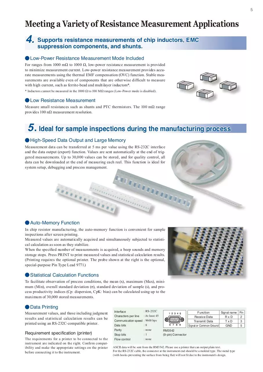
Data Printing
Measurement values, and those including judgment
results and statistical calculation results can be
printed using an RS-232C-compatible printer.
Requirement specification (printer)
The requirements for a printer to be connected to the
instrument are indicated on the right. Confirm compatibility and make the appropriate settings on the printer
before connecting it to the instrument.
Interface
Characters per line
Communication speed
Data bits
Parity
Stop bits
Flow control
: RS-232C
: At least 45
: 9600 bps
:8
: none
:1
: none
Function
Signal name Pin
Receive Data
RxD
2
Transmit Data
TxD
3
Signal or Common Ground
GND
5
RM3542
(9-pin) Connector
ASCII data will be sent from the RM3542. Please use a printer that can output plain text.
For the RS-232C cable, the connector at the instrument end should be a molded type. The metal type
(with hooks preventing the surface from being flat) will not fit due to the instrument's design.
6
6 . Engineered with the speed and accuracy required for automated systems
Total Productivity Supported by Fast and Accurate Measurements
• Provides the speed and accuracy required for automated systems
Contact to decision output in as little as 0.9 ms. Contact improvement, measurement and contact checking, and decision output are
all completed within this interval.
Measurement Times
(1) With Low Power disabled*1
Values in parenthesis are for 50 Hz (where timing depends on
line frequency), units are in milliseconds
Range
100 mΩ
1000 mΩ
10 Ω
100 Ω
1000 Ω
10 kΩ
100 kΩ
1000 kΩ
10 MΩ
100 MΩ
• All data can be imported in real time using the 38.4-kbps RS232C interface.
• Model RM3542-01 also includes a GP-IB interface.
(2) With Low Power enabled*1
Values in parenthesis are for 50 Hz (where timing depends
on line frequency), units are in milliseconds
Measurement Speed
FAST
MED
SLOW
3.8
13
36 (43)
2.0
6.4
35 (41)
1.6
6.0
34 (41)
0.9
3.6
17 (21)
0.9
3.6
17 (21)
1.0
3.6
17 (21)
1.3
3.8
18 (21)
2.5
6.0
18 (21)
5.3
20 (23)
20 (23)
22 (26)
39 (46)
72 (86)
Range
1000 mΩ
10 Ω
100 Ω
1000 Ω
FAST
2.5
2.5
1.7
7.2
Measurement Speed
MED
SLOW
12
35 (42)
12
35 (42)
6.1
34 (41)
12
40 (47)
Tolerance: ±10% ±0.2 ms
*1. Under default settings except those specified, without retries.
Tolerance: ±10% ±0.2 ms
EXT I/O Handler Interface
For noise immunity, the EXT I/O handler interface is isolated from the measurement and control circuits.
Example of Typical EXT I/O Timing
Contact Condition
Connect
TRIG
INDEX
Open
ON
OFF
t0
t1
t2
t3
ON
OFF
ON
OFF
t4
EOM
t5
HI,IN,LO
ERR,CE_HI,CE_LO
PRB_SHORT
t6
OFF
t0: Trigger pulse on time; at least 0.1 ms
t1: Trigger pulse off time; at least 0.1 ms
t2: Delay 1; 0 to 100 ms (per setting)
t3: Delay 2; 0 to 100 ms (per setting)
t4: Measurement time; 0.1 to 100 ms (per sampling speed, OVC on/off, delay, and line
frequency)
t5: Calculation time; 0.1 ms
t6: EOM pulse width; 1 to 100 ms (per setting)
EXT I/O Input and Output Circuits
Input Circuit
RM3542
Internally Isolated 5 V
2kΩ
Output Circuit
(open-collector)
RM3542
Internally Isolated 5 V
Input
1kΩ
ISO_COM
Internally Isolated
Common
10Ω
ISO_5V
Output
Max. 50 mA DC
Zener voltage
= 30 V
Internally Isolated
Common
ISO_COM
Example of Typical
Input Signals
TRIG
HOLD
KEY_LOCK
0ADJ
CAL
PRB_CHECK
Output Signals
HI
IN
LO
EOM
INDEX
ERR
PRB_SHORT
CE_HI
CE_LO
ISO_5V
ISO_COM
: External trigger
: Hold
: Key-Lock
: Zero-Adjust
: Self-Calibration
: Probe Short-Circuit Detection
: Comparator Hi
: Comparator IN
: Comparator Lo
: End of Measurement
: End of Import
: Measurement Fault Output
: Probe short-circuit error
: Probe (HI sense) contact error
: Probe (LO sense) contact error
: Internally Isolated 5 V
: Internally Isolated Common
EXT I/O Electrical Specifications
Inputs:
Photocoupler isolation: Non-voltage contact
inputs
Assert: 0 to 1 V (with 3 mA input)
De-assert: Open, or 5 to 30 V
Outputs:
Photocoupler isolation: Open-collector NPN
Max. 30 V and 50 mA per ch.
Residual voltage: Max. 1.5 V @50 mA,
or 1 V @10 mA.
Accessory Power Out (internally powered):
4.5 to 5 V DC @ 100 mA max.
Isolated from protective ground and measurement circuitry
7
Multiple Test Fixture Options
Various fixtures available to suite the type of components to measure
Noise-suppressing BNC-type measurement jacks are employed.
Ready availability and easy assembly ensure smooth system setup.
A variety of test fixtures for HIOKI LCR HiTESTERs can also be used.
4-TERMINAL PROBE 9140
Cable length: 1 m
TEST FIXTURE 9262
Residual resistance: 10 mΩ or less
SMD TEST FIXTURE 9263
Sample size: 1 to 10 mm
Residual resistance: 10 mΩ or less
Recommended Measurement Cable Specifications
Conductor resistance
Capacitance
Length
Specific examples
500 mΩ/m or less
150 pF/m or less
2 m or less
JIS std. 3C-2V and 1.5D-2V,
MIL std. RG-58A/U
RM3542 Measurement Accuracy
Accuracy guaranteed for 1 year, Post-adjustment accuracy guaranteed for 1 year (@23 ±5ºC, 80% rh or less)
(1) Resistance Measurement (Low-Power OFF)
Accuracy = ±(% rdg. + % f.s.)
(f.s. = calculated 1,000,000 dgt., where 0.001% f.s. = 10 dgt.)
Range
100 mΩ
1000 mΩ
10 Ω
100 Ω
1000 Ω
10 kΩ
100 kΩ
1000 kΩ
10 MΩ
100 MΩ
Maximum
display Value*1
120.0000 mΩ
1200.000 mΩ
12.00000 Ω
120.0000 Ω
1200.000 Ω
12.00000 kΩ
120.0000 kΩ
1200.000 kΩ
12.00000 MΩ
120.0000 MΩ
Example. 0.015 + 0.008 ..... 0.015% rdg. + 0.008% f.s.
Resolution
FAST
MEDIUM
100 nΩ
1 µΩ
10 µΩ
100 µΩ
1 mΩ
10 mΩ
100 mΩ
1Ω
10 Ω
100 Ω
0.015+0.008
0.012+0.003
0.010+0.003
0.009+0.003
0.008+0.003
0.009+0.003
0.010+0.003
0.010+0.003
0.015+0.003
0.012+0.002
0.008+0.002
0.007+0.002
0.006+0.002
0.007+0.002
0.007+0.002
0.008+0.002
0.030+0.004
0.100+0.020
Measurement Open-Circuit
Voltage
Current*2
0.015+0.002
100 mA
0.012+0.001
100 mA
0.008+0.001
10 mA
0.007+0.001
10 mA
0.006+0.001
1 mA
20 Vmax*3,*4
0.007+0.001
1 mA
0.007+0.001
100 µA
0.008+0.001
10 µA
1 µA
100 nA
SLOW
(2) Resistance Measurement (Low-Power ON)
Range
1000 mΩ
10 Ω
100 Ω
1000 Ω
Maximum
display Value*1
1200.000 mΩ
12.00000 Ω
120.0000 Ω
1200.000 Ω
Resolution
FAST
MEDIUM
1 µΩ
10 µΩ
100 µΩ
1 mΩ
0.010+0.008
0.010+0.008
0.010+0.003
0.020+0.003
0.008+0.003
0.008+0.003
0.008+0.002
0.008+0.002
Measurement Open-Circuit
Voltage
Current*2
0.008+0.002
10 mA
0.008+0.002
1 mA
20 Vmax*3,*4
0.008+0.001
1 mA
0.008+0.001
100 µA
SLOW
*1. Negative values can be up to 10% of positive full scale.
*2. Measurement current accuracy is ±5%.
*3. Voltage when not measuring is 20 mV or less, with current mode set at PULSE and Contact Improver Setting set at OFF/PULSE (measured with a
voltmeter having 10 MΩ).
*4. With the sum of resistances of the cables, sample, and contacts less than (open-circuit voltage) / (measurement current).
Example. 100 mA measurement current can be used when the sum of resistances of the cables, sample, and contacts is no more than 20 Ω.
Conditions of Guaranteed Accuracy
After 30-minute warm-up time
Add ±(0.1% measurement accuracy)/ºC to the above between 0 and 18ºC, and between 28 and 40ºC, respectively
Temperature variation after self-calibration must be within ±2ºC.
RM3542 Specifications
Measurement
types
Measurement
method
Range switching
Zero-Adjust
Trigger
Sampling
Integration time
setting function*1
Four-terminal resistance measurement
0.0000 mΩ (100 mΩ range) to 120.0000 MΩ
Low-power four-terminal resistance measurement
0.000 mΩ (1000 mΩ range) to 1200.000 Ω
Four-terminal, constant-current DC
Measurement terminals: 22-mm BNC female
jacks
Comparator on: Auto-range setting according to
comparator reference or upper threshold setting.
Comparator off: Manual range setting
Range: -1 to 10 Ω (wiring resistance compensation for two-terminal measurements)
Internal or External
Fast, Medium, and Slow
0.1 to 100.0 ms, PLC*2 setting available
1 to 5 PLC @ 50 Hz, 1 to 6 PLC @60 Hz
*2. One PLC = one power line cycle (mains waveform
period)
DELAY1 = Set to allow for mechanical delay of
trigger input and probing (affects all ranges),
from 0.0 to 100.0 ms
DELAY2*1 = Set to allow for measurement object
response (each range independently), from 0.0
to 100.0 ms
Self-calibration, probe short-circuit detection,
Contact Improver, current mode setting, OVC
(offset voltage compensation), settings monitor,
retry, statistical calculations, key-lock, comparator (relative tolerance or absolute range modes),
EOM pulse width setting, data export, export
data format, auto-memory
Delay
Functions
Measurement
fault detection
functions
Memory storage
Interfaces
RS-232C bit rates
Out-of-range detection, contact check, current
monitor, voltage monitor
30,000 values (volatile memory, no backup)
EXT I/O, RS-232C, Printer, Settings Monitor
Functional terminals (SET MONITOR)
GP-IB (Model RM3542-01)
9,600, 19,600, or 38,400 bps
*1. Settable for each range independently
RM3542 General Specifications
Operating temperature and humidity
0 to 40ºC, 80% rh or less (non-condensating)
Temperature and
humidity range for
guaranteed accuracy
23 ±5ºC, 80% rh or less (non-condensating)
Storage temperature
10 to 50ºC, 80% rh or less (non-condensating)
and humidity
Operating
environment
Rated mains supply
voltage
Indoors, Pollution Degree 2, up to 2,000 m ASL
100 to 240 V AC ±10%
Rated mains supply
frequency
50 / 60 Hz
Power consumption
30 VA
Insulation withstand potential
Dimensions
Mass
Accessories
Applicable
Standards
1.69 kV AC for 15s, with 10 mA cutoff current
Between all mains supply terminals and protective ground, interfaces, and measurement jacks
Approx. 260W × 88H × 300D mm (without projections)
Approx. 2.9 kg
Power cord × 1, EXT I/O male connector × 1,
Operation manual × 1, Operation guide × 1
Safety
EN61010
EMC
EN61326
EN61000-3-2
EN61000-3-3
Ordering information
RESISTANCE HiTESTER RM3542
RESISTANCE HiTESTER RM3542-01 (with GP-IB interface)
Test fixtures are not supplied with the unit.
Select an optional test fixture when ordering.
Optional accessories
FOUR-TERMINAL PROBE 9140
TEST FIXTURE 9262 (direct connection type)
SMD TEST FIXTURE 9263 (direct connection type)
GP-IB CONNECTION CABLE 9151-02 (2 m)
RS-232C CABLE 9637 (9pin-9pin, cross, 1.8 m (5.91 ft) length)
RS-232C CABLE 9638 (9pin-25pin, cross, 1.8 m (5.91 ft) length)
Note: Company names and Product names appearing in this catalog are trademarks or registered trademarks of various companies.
HIOKI (Shanghai) SALES & TRADING CO., LTD.
TEL +86-21-63910090 FAX +86-21-63910360
http://www.hioki.cn / E-mail: info@hioki.com.cn
РАДАР - ОФИЦИАЛЬНЫЙ ДИЛЕР HIOKI
HIOKI INDIA PRIVATE LIMITED
TEL +91-124-6590210
HEADQUARTERS
E-mail: hioki@hioki.in
81 Koizumi, Ueda, Nagano, 386-1192, Japan
TEL +81-268-28-0562 FAX +81-268-28-0568
HIOKI SINGAPORE PTE. LTD.
http://www.hioki.com / E-mail: os-com@hioki.co.jp TEL +65-6634-7677 FAX +65-6634-7477
E-mail: info-sg@hioki.com.sg
HIOKI USA CORPORATION
HIOKI KOREA CO., LTD.
TEL +1-609-409-9109 FAX +1-609-409-9108
TEL +82-2-2183-8847 FAX +82-2-2183-3360
http://www.hiokiusa.com / E-mail: hioki@hiokiusa.com E-mail: info-kr@hioki.co.jp
All information correct as of Sept. 30, 2015. All specifications are subject to change without notice.
РОССИЯ, 198152, Санкт-Петербург
Краснопутиловская ул., д.25
Тел./факс +7 (812) 600-48-89
Тел.: +7 (812) 375-32-44
www.radar1.ru
RM3542E4-59E
Printed in Japan
info@radar1.ru
Download HIOKI RM3542 ENG
HIOKI_RM3542_ENG.pdf (PDF, 2.58 MB)
Download PDF
Share this file on social networks
Link to this page
Permanent link
Use the permanent link to the download page to share your document on Facebook, Twitter, LinkedIn, or directly with a contact by e-Mail, Messenger, Whatsapp, Line..
Short link
Use the short link to share your document on Twitter or by text message (SMS)
HTML Code
Copy the following HTML code to share your document on a Website or Blog
QR Code to this page

This file has been shared publicly by a user of PDF Archive.
Document ID: 0000326710.