HIOKI UA1782 ENG (PDF)
File information
Title: FAIL VISUALIZER UA1782 Series
Author: HIOKI
This PDF 1.7 document has been generated by Adobe InDesign CS5.5_J (7.5.3) / Adobe PDF Library 9.9, and has been sent on pdf-archive.com on 25/12/2015 at 07:54, from IP address 5.18.x.x.
The current document download page has been viewed 468 times.
File size: 2.47 MB (4 pages).
Privacy: public file


File preview
FAIL VISUALIZER UA1782 Series
Automatic Testing
Equipment
VISUALIZE populated board test results…
▲
PLUS bare board test results.
Click
Visualize information about board defects with a single click.
Robust support for repair work through simple operation and assistive functionality
Use the UA1782 as a tool to support repair and analysis work conducted away from testing equipment.
Dedicated visualization software for Hioki electrical testing equipment
and data creation systems
• Visualize test results from flying-probe testers
• Pinpoint components and patterns from test result files
• Display the probing positions of test fixtures or test heads for both ICT and
bare board testers
• Search for components and nets on device embedded substrates
2
Quickly find the locations of failed components
Get started quickly with real-time file loading
Flying probe tester
FAIL
Files displayed along with a FAIL-MAP you can...
See all defects
▲
Choose to view
Click
Pinpoint view of the
selected component
Automatic FAIL-MAP generation
Fail files can be either loaded automatically or specified using barcodes. When a file is
loaded, the FAIL-MAP is updated, and all fail locations are displayed.
Only the selected entry in the fail list is
displayed, and its checkbox will be selected
once you have finished reviewing that point.
Since you can select only the information you wish to view, you can…
View pin numbers
View probing positions
View the opposite side
21 22 23 24 25 26 27 28 29 3
Component pin number display
Simultaneous display of pin numbers
allows easy identification of the location
of pseudo-contact defects.
Component name reverse-search function
Highlighting of probing points
If all mounting information has been
registered, you can search for locations
by component name.
Automatic zoom-in function
Automatic detection of whether results
are for the top or bottom of the board
The software automatically determines
whether the loaded data describes the
top or bottom of the board.
Only the FIT-LINE UA1780 database is required.
To prepare to use the visualizer, you need only import the database and specify the location of test result files on
your network. There’s no need to bring hard copies of the BOM, component layouts, or pin maps to the worksite.
UA database
Import
Real-time monitoring
Barcode file loading
*Or use U-ART data.
3
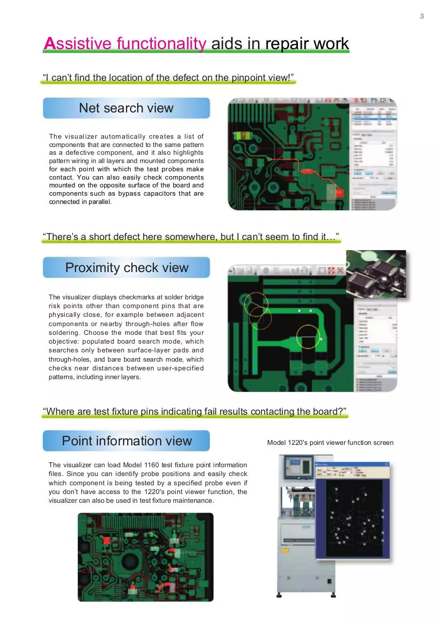
Assistive functionality aids in repair work
“I can’t find the location of the defect on the pinpoint view!”
Net search view
The visualizer automatically creates a list of
components that are connected to the same pattern
as a defective component, and it also highlights
pattern wiring in all layers and mounted components
for each point with which the test probes make
contact. You can also easily check components
mounted on the opposite surface of the board and
components such as bypass capacitors that are
connected in parallel.
“There’s a short defect here somewhere, but I can’t seem to find it…”
Proximity check view
The visualizer displays checkmarks at solder bridge
risk points other than component pins that are
physically close, for example between adjacent
components or nearby through-holes after flow
soldering. Choose the mode that best fits your
objective: populated board search mode, which
searches only between surface-layer pads and
through-holes, and bare board search mode, which
checks near distances between user-specified
patterns, including inner layers.
“Where are test fixture pins indicating fail results contacting the board?”
Point information view
The visualizer can load Model 1160 test fixture point information
files. Since you can identify probe positions and easily check
which component is being tested by a specified probe even if
you don’t have access to the 1220's point viewer function, the
visualizer can also be used in test fixture maintenance.
Model 1220's point viewer function screen
Extensive analysis functionality for bare board testing
The UA1782 also provides dedicated functionality to aid in bare board repair work, enabling it to provide robust backup for users of bare board testers.
Highlighting of nets in all layers
Importing of FLY-LINE databases and net searches for all layers
Display of device embedded substrates Importing of EPA-LINE databases and display of embedded devices in inner layers
Capacitance S/O checking
Searching for defective nets and points based on measured capacitance values
Address searching
Importing of CAN data for analysis and net searches using address numbers
■ FAIL VISUALIZER UA1782 Specifications
Product variants
Supports UA1780 database input
UA1782
Supports IPC-D-356 format input
UA1782-01
Supports CAN & ADR formats input
UA1782-02
Contents
Install CD, license key (USB), instruction manual
*Note: User is responsible for providing a computer, monitor, and other hardware.
Function details
Database import
Load UA1780 and U-ART databases.
Net highlighting
Display user-specified nets with color highlighting. The user can select whether to display all layers or only top and bottom layers.
Fail list loading with real-time monitoring
Monitor a test result output folder for a testing system at a specified interval and automatically load new test data as it becomes available.
Pattern proximity check view
Generate checkmarks at points lying at or below a user-specified distance between two nets for all layers.
Pad proximity check view
Generate checkmarks at points lying close to locations at which a conductor is exposed (i.e., areas without resist), limited to the surface layer.
Net component connection display (net search view)
Display components that are connected to the specified net.
Point information search
Load a point information file from a 1220 in-circuit tester and search for components by populated board fixture pin number.
Address search
Load CAN data and ADR-format files for use in analyzing bare board test fixtures and search by address number.
Display of device embedded substrates
Import EPA-LINE databases and display defective embedded devices on inner layers.
Capacitance short/open check
Search for test points near wiring breaks and short-circuited nets based on capacitance values from bare board test results.
Barcode file loading
Search for fail files by barcode and load them.
Work check history
Add a check history to test steps and test files that have been checked.
Recommended operating environment
Supported operating system
Windows 7 Professional 64-bit
CPU
Core i7 or equivalent
RAM
4 GB or more
Display resolution
1920 × 1080 or greater
Available disk space
80 GB or more
■ Functionality by testing system
FA1240 *1
1116,127x
FA1282
FA1232
Fail list loading with real-time monitoring
4
4
4
4
Pattern proximity check view
1220
4 *2
Bare board test fixture
N/A
4
4
4
4
4
4
Pad proximity check view
4
N/A
N/A
N/A
N/A
N/A
Net component connection display (net search view)
4
4
4
4
4
4
Point information search
N/A
N/A
N/A
N/A
4
N/A
Address search
N/A
N/A
N/A
N/A
N/A
4
Display of device embedded substrates
4
4
4
4
N/A
4
N/A
4
4
N/A
N/A
N/A
Barcode file loading
4
4
4
4
4 *2
N/A
Work check history
4
4
4
4
N/A
N/A
Capacitance short/open check
*1 Customers using the 1240 will need to upgrade their system to the FA1240 before using this product.
*2 Please contact your distributor for more information about using list loading functionality with the 1220.
Note: Company names and Product names appearing in this catalog are trademarks or registered trademarks of various companies.
HIOKI (Shanghai) SALES & TRADING CO., LTD.:
TEL +86-21-63910090 FAX +86-21-63910360
http://www.hioki.cn / E-mail: info@hioki.com.cn
РАДАР - ОФИЦИАЛЬНЫЙ ДИЛЕР HIOKI
HIOKI INDIA PRIVATE LIMITED:
TEL +91-124-6590210 FAX +91-124-6460113
HEADQUARTERS:
E-mail: hioki@hioki.in
81 Koizumi, Ueda, Nagano, 386-1192, Japan
TEL +81-268-28-0562 FAX +81-268-28-0568 HIOKI SINGAPORE PTE. LTD.:
http://www.hioki.com / E-mail: os-com@hioki.co.jp TEL +65-6634-7677 FAX +65-6634-7477
E-mail: info-sg@hioki.com.sg
HIOKI USA CORPORATION:
HIOKI KOREA CO., LTD.:
TEL +1-609-409-9109 FAX +1-609-409-9108 TEL +82-42-936-1281 FAX +82-42-936-1284
http://www.hiokiusa.com / E-mail: hioki@hiokiusa.com E-mail: info-kr@hioki.co.jp
All information correct as of May 2, 2014. All specifications are subject to change without notice.
РОССИЯ, 198152, Санкт-Петербург
Краснопутиловская ул., д.25
Тел./факс +7 (812) 600-48-89
Тел.: +7 (812) 375-32-44
www.radar1.ru
UA1782E1-45B
Printed in Japan
info@radar1.ru
Download HIOKI UA1782 ENG
HIOKI_UA1782_ENG.pdf (PDF, 2.47 MB)
Download PDF
Share this file on social networks
Link to this page
Permanent link
Use the permanent link to the download page to share your document on Facebook, Twitter, LinkedIn, or directly with a contact by e-Mail, Messenger, Whatsapp, Line..
Short link
Use the short link to share your document on Twitter or by text message (SMS)
HTML Code
Copy the following HTML code to share your document on a Website or Blog
QR Code to this page

This file has been shared publicly by a user of PDF Archive.
Document ID: 0000326728.