DesignReview (PDF)
File information
This PDF 1.4 document has been generated by / Skia/PDF, and has been sent on pdf-archive.com on 29/02/2016 at 01:31, from IP address 130.126.x.x.
The current document download page has been viewed 424 times.
File size: 340.43 KB (20 pages).
Privacy: public file


File preview
Solar Powered LED Blinds
Design Review
Group 28: Austin Estes & Kerr Oliva
TA: Katherine O’Kane
ECE 445
February 15, 2016
Table of Contents
1 Introduction
1.1 Statement of Purpose
1.2 Objectives
1.2.1 Goals and Benefits
1.2.2 Functions and Features
2 Design
2.1 Block Diagrams
2.1.1 Power Block Diagram
2.1.2 Signal Block Diagram
2.2 Block Descriptions
2.2.1 Solar Panels
2.2.2 Charge Controller
2.2.3 Liion Battery
2.2.4 Buck Converter
2.2.5 Microcontroller
2.2.6 Electric Motor
2.2.7 RGB LEDs
2.2.8 User Inputs
2.2.9 Motor Driver
2.2.10 Voltage Controlled Current Source
2.3 Schematics of Overall System
2.4 Simulations and Calculations
2.4.1 Charge Time
2.4.2 LED Discharge Time
2.4.3 Total Battery Discharge Time
3 Requirements and Verifications
3.1 Requirements and Verifications Tables
3.1.1 Solar Panels
3.1.2 Charge Controller
3.1.3 Liion Battery
3.1.4 Buck Converter
3.1.5 Microcontroller
3.1.6 Electric Motor
3.1.7 RGB LEDs
1
3.1.8 Voltage Controlled Current Source
3.2 Tolerance Analysis
3.3 Safety
3.4 Code of Ethics
4 Cost and Schedule
4.1 Cost Analysis
4.1.1 Labor
4.1.2 Parts
4.1.3 Total Cost
4.2 Schedule
5 References
5.1 References
2
1 Introduction
1.1 Statement of Purpose
The goal for this project is to create a selfcontained system powered solely by solar
panels that can bring light to a room, whether it be to help illuminate the room with white light or
add a more aesthetic appeal using a different color of light. This way the blinds cannot only
block out the sun’s light from a room during the day, but can store the sun’s energy for use later
at night.
The solar panels will be placed on the blinds, so that they can be angled towards the sun
either by the user or by the microcontroller. This should allow for the maximum power
production depending on the current conditions outside. The solar panels will charge a
rechargeable lithiumion battery, which will power the electric motor which turns the blinds, the
microcontroller, and the RGB LEDs. The electric motor will be controlled by the microcontroller
using solar data to determine where the best angle is for the blinds. The user will be able to
choose the intensity of the red, green, and blue light from the LEDs individually, creating a
massive selection of custom colors.
Our hope was to be able to create a product that someone could use in his/her home to get
the benefits of green energy, without having to do an expensive retrofit. Our project could also
be used in an area where electric power is not readily available or not reliable, that way the user
could have an electric light source at night.
1.2 Objectives
1.2.1 Goals and Benefits
● Entirely selfcontained
● Offer additional lighting in conjunction with normal illumination appliances
● Automatically angle blinds for best solar power production
1.2.2 Functions and Features
● Solar charged liion battery
● Automated electric motor movements
● Customizable RGB LED output
● DC Motor able to turn in either direction
3
2 Design
2.1 Block Diagrams
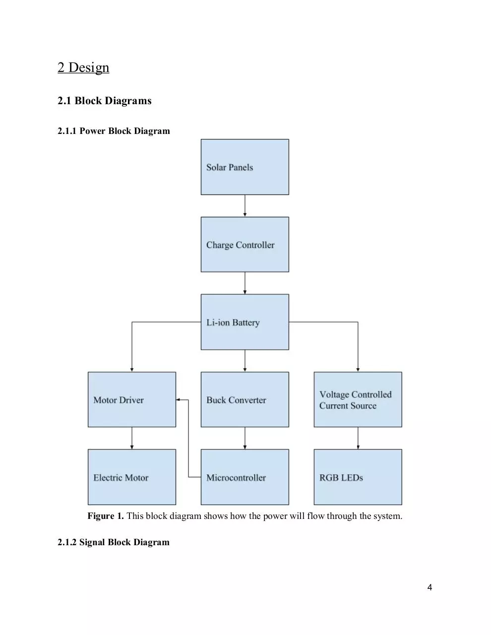
2.1.1 Power Block Diagram
Figure 1.
This block diagram shows how the power will flow through the system.
2.1.2 Signal Block Diagram
4
Figure 2.
This block diagram shows how signals will travel through the system.
2.2 Block Descriptions
2.2.1 Solar Panels
Input:
Output:
18 V
0.63 A
11.34 W
Each solar panel individually produces 6 V and 0.07 A of power. With this in mind, we
plan to have 27 solar panels connected in an array, with 3 solar panels to each blind. This gives 9
blinds that will contain solar panels. Similarly, 3 solar panels will be connected in series to
produce 18 V, and each group will be connected in parallel to produce 0.63 A. This way the
charge controller can drop the voltage down to the recommended 12.6 V to charge the battery at
0.9 A. It would take the solar panels 7 hours and 20 minutes in the best conditions to fully charge
the liion battery. With the least amount of daylight time in Champaign being 9 hours and 20
minutes, this gives 2 hours of leeway in case of clouds.
2.2.2 Charge Controller
Input: 18 V
0.63 A
5
11.34 W
Output:
12.6 V
0.9 A
11.34 W
The charge controller can step down the input voltage in order to output the voltage
recommended to charge the attached battery. It also increases the output current in relation to the
input current, which will speed up the charging time for the battery. This helps during the day,
since the amount of power being output by the solar panels can fluctuate such as on a partly
cloudy day. The charge controller should keep the voltage at a steady 12.6 V, only changing the
current output, which in turn changes the charge time.
2.2.3 Liion Battery
Input: 12.6 V
0.9 A
11.34 W
Output:
11.1 V
5.7 A (max)
Every component that requires power will be supplied by a 6600 mAh rechargeable liion
battery. [2] In between the motor, microcontroller, and LEDs will be voltage step downs to get to
each’s required voltage, so nothing burns up. We choose this battery for many reasons, such as
its slim form factor, its charge capacity which will allow it to charge fully during the day and last
through the night, and the voltage and current output.
2.2.4 Buck Converter
2.2.5 Microcontroller
Input: 11.1 V
? A
Output:
5 V
1.5 A
The microcontroller will be controlling the motor and the RGB LEDs. It will be using
data in order to determine what angle to position the blinds for the best solar panel efficiency.
Between the microcontroller and the motor will be a Hbridge, specifically an Hbridge chip.
This will allow the microcontroller to send three signals in order to spin the motor in different
directions. The enable signal enables the motor to spin, and then there are 2 different direction
6
signals used by the microcontroller to easily control the direction of rotation. The microcontroller
will also interpret user inputs and control the LEDs accordingly.
2.2.6 Electric Motor
Input: 3 V
0.04 0.4 A
Output:
The electric motor will be getting different amounts of current depending on the
microcontroller’s output when the system to set to automatic. This way the motor will turn the
blinds to the correct position determined by the microcontroller for the most efficient production
of energy. The motor will be controlled by the microcontroller using an Hbridge, which will
allow the DC motor to spin in either direction. [4] The highest amount of current the motor can
draw is 0.4 A, which is the stall current. [3]
7
Figure 3.
This is the circuit for the motor, showing how using an Hbridge chip can enable the
motor to be spun in two different directions instead of only one.
2.2.7 RGB LEDs
Input: 2 V (red)
3.2 V (green)
3.2 V (blue)
0.02 A (all)
5.04 W total
Output:
8
Download DesignReview
DesignReview.pdf (PDF, 340.43 KB)
Download PDF
Share this file on social networks
Link to this page
Permanent link
Use the permanent link to the download page to share your document on Facebook, Twitter, LinkedIn, or directly with a contact by e-Mail, Messenger, Whatsapp, Line..
Short link
Use the short link to share your document on Twitter or by text message (SMS)
HTML Code
Copy the following HTML code to share your document on a Website or Blog
QR Code to this page

This file has been shared publicly by a user of PDF Archive.
Document ID: 0000343903.