LayerZero Series 70 4 pole eSTS (PDF)
File information
This PDF 1.5 document has been generated by Adobe InDesign CS6 (Windows) / Adobe PDF Library 10.0.1, and has been sent on pdf-archive.com on 14/04/2016 at 18:03, from IP address 173.189.x.x.
The current document download page has been viewed 478 times.
File size: 5.05 MB (18 pages).
Privacy: public file


File preview
Series 70 eSTS
4-Pole STS + SafePanel™ Distribution
Product Brochure
Series 70 eSTS + Distribution
250 A -800 A, 4-Pole Static Transfer Switch
The 4-Pole eSTS Lowers Infrastructure Costs While Maintaining High Reliability
Increasingly, data center operators aspire to increase their energy efficiency; and thus reduce their operating costs
and their carbon footprint. A popular technique deployed to achieve higher efficiency of critical operations is to
minimize the number of AC power transformations between the building entrance to the eventual critical load.
Facilities are being designed to step down voltage at the incoming sub-station to 240/415 V level; and UPS systems
are being deployed with native 4-wire, 240/415 V output. Critical loads are operated at 240 V L-N. The cost of
cabling in the facility is optimized at a higher voltage; and the loss of efficiency from another voltage transformation
to 120/208 V is avoided.
Against this back drop and in an environment which provides two independent sources of power, if a static
transfer switch is needed to increase the reliability of power to the critical load; and/or to increase the concurrent
maintainability of the facility’s electrical infrastructure then the static transfer switch must be a four pole switch. The
transfer mechanism must transfer phase conductors (A, B & C) in an open transition manner; while ensuring that the
transfer of the neutral between adjacent sources is completed without interruption to the neutral conductor.
LayerZero’s 4-pole eSTS is the most reliable, connected and information centric product designed for this application.
LayerZero uniquely uses SCR based solid-state transfers for phases A, B, C and Neutral. Further, for operator safety
LayerZero deploys 4-pole breakers for input, output and bypass isolation.
480 V, 600 V, or MV
Substation 1 or UPS 1
480 V, 600 V, or MV
Substation 2 or UPS 2
120/208 V
or 240/415V
120/208 V
or 240/415V
Remote
Power
Panels
4-Pole
Static Transfer Switch
Distribution
2
© Copyright 2016 LayerZero Power Systems, Inc.
WallMounted
Power
Panels
Overhead
Busways
Series 70 eSTS + Distribution
250 A -800 A, 4-Pole Static Transfer Switch
The LayerZero Integrated Solution: eSTS + Distribution
Maximizes Power Reliability
eSTS Automatically Transfers Between Two Power Sources
The Series 70 eSTS is a solid-state transfer switch that automatically or manually provides solid state
transfers between two in-phase AC sources in a quarter cycle. The eSTS performs open-transition
transfer in such a manner that the connected load disruption is minimized without ever crossconnecting the power sources. One power source is selected to be the preferred source. If the
preferred source fails the load is automatically and seamlessly connected to the alternate source by
means of an open-transition static transfer.
* Optional Sub-feed Monitor
3
© Copyright 2016 LayerZero Power Systems, Inc.
Series 70 eSTS + Distribution
250 A -800 A, 4-Pole Static Transfer Switch
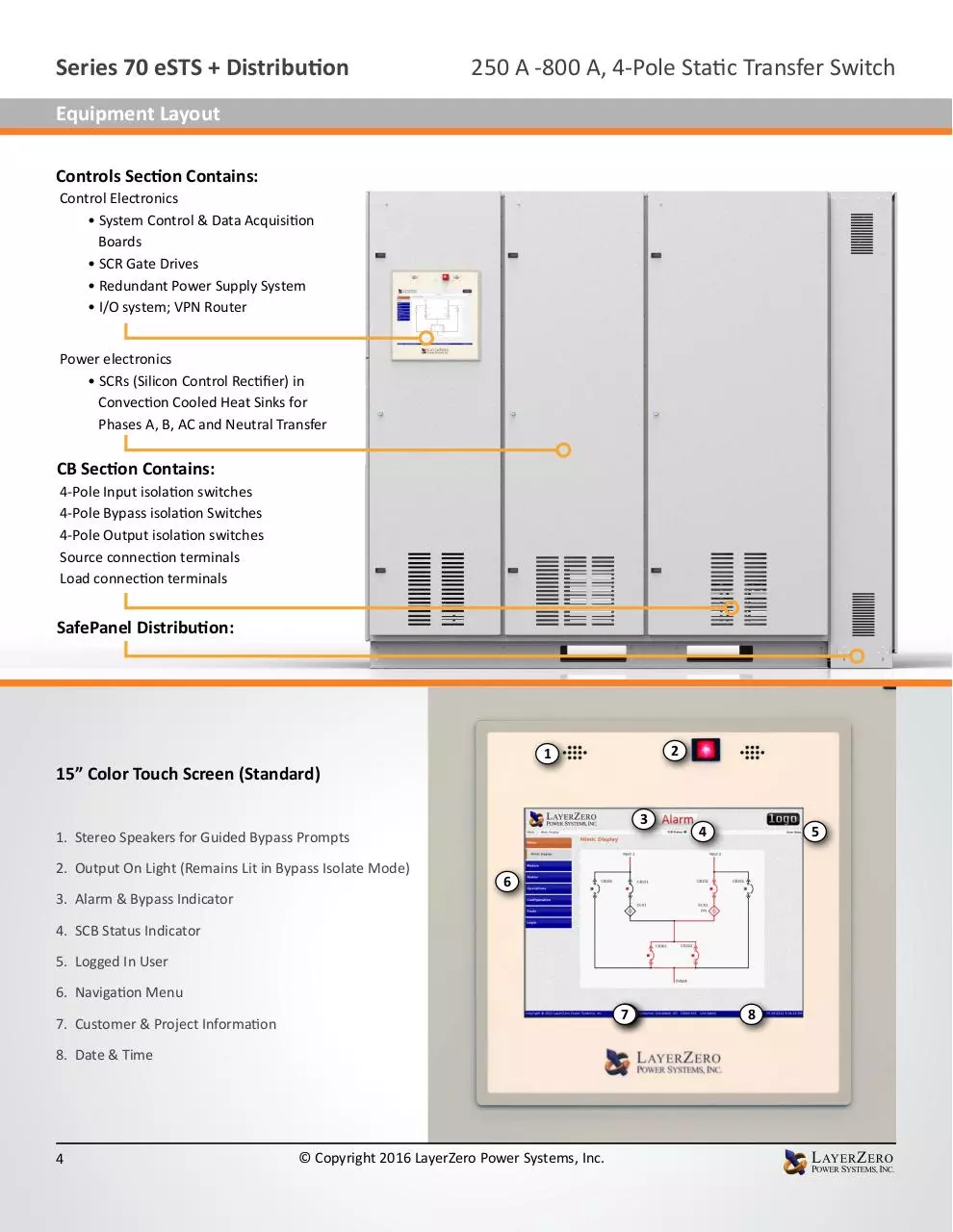
Equipment Layout
Controls Section Contains:
Control Electronics
• System Control & Data Acquisition
Boards
• SCR Gate Drives
• Redundant Power Supply System
• I/O system; VPN Router
Power electronics
• SCRs (Silicon Control Rectifier) in
Convection Cooled Heat Sinks for
Phases A, B, AC and Neutral Transfer
CB Section Contains:
4-Pole Input isolation switches
4-Pole Bypass isolation Switches
4-Pole Output isolation switches
Source connection terminals
Load connection terminals
SafePanel Distribution:
2
1
15” Color Touch Screen (Standard)
3
1. Stereo Speakers for Guided Bypass Prompts
2. Output On Light (Remains Lit in Bypass Isolate Mode)
3. Alarm & Bypass Indicator
4
5
6
4. SCB Status Indicator
5. Logged In User
6. Navigation Menu
20
7
7. Customer & Project Information
8. Date & Time
4
© Copyright 2016 LayerZero Power Systems, Inc.
8
Series 70 eSTS + Distribution
250 A -800 A, 4-Pole Static Transfer Switch
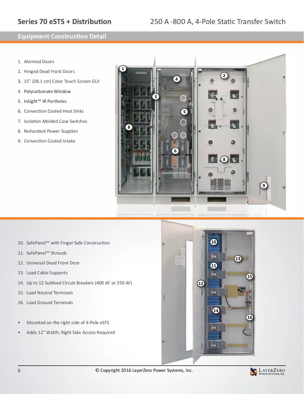
Equipment Construction Detail
1. Alarmed Doors
1
2. Hinged Dead Front Doors
2
4
3. 15” (38.1 cm) Color Touch Screen GUI
4. Polycarbonate Window
3
5. InSight™ IR Portholes
6. Convection Cooled Heat Sinks
5
7. Isolation Molded Case Switches
8
8. Redundant Power Supplies
9. Convection Cooled Intake
6
8
9
10
10. SafePanel™ with Finger Safe Construction
11. SafePanel™ Shrouds
13
12. Universal Dead Front Door
11
13. Load Cable Supports
15
14. Up to 12 Subfeed Circuit Breakers (400 AF or 250 AF)
12
15. Load Neutral Terminals
16. Load Ground Terminals
14
•
Mounted on the right side of 4-Pole eSTS
•
Adds 12” Width; Right Side Access Required
5
© Copyright 2016 LayerZero Power Systems, Inc.
16
Series 70 eSTS + Distribution
250 A -800 A, 4-Pole Static Transfer Switch
Product Features/Reliability Overview
800 A, 4-Pole eSTS Product Features
Reliability
Safety
Safe Bypass Procedure
InSight™ IR Portholes
Waveform Capture
Voice Guided Bypass
Sectionalized Components
“Black Box” Forensic Diagnostics
Optional Triple Modular Redundancy
Polycarbonate Windows
Touch Screen Interface
Epoxy Coated Buswork
Front-Only Access
Waveforms Automatically Emailed
Silver Plated Terminals
Dead-Front Hinged Doors
Maintenance-Free Joints
Connectivity
Machined Hardware
Screw Thread Inserts
Ethernet Connectivity
Convection Cooling
Modbus/TCP
Optical Fiber Based Controls
NTP Time Clock Synchronization
Serialized Critical Board Tracking
SNMP Connectivity
LayerZero eSTS Reliability Overview
The LayerZero eSTS Provides Many Dimensions of Reliability:
• Control System Reliability
• SMR (Single Module Redundancy, Standard)
• TMR (Triple Modular Redundancy, Optional)
• Control Power Supply Reliability
• Signal Reliability
• Operator Procedural Reliability
6
© Copyright 2016 LayerZero Power Systems, Inc.
Series 70 eSTS + Distribution
250 A -800 A, 4-Pole Static Transfer Switch
Reliability Features: Control System Reliability
Single Module Redundancy (SMR) Reliability (Standard)
Single Module Redundancy is a cost-effective topology
Fiber Optics
that provides redundant power paths to mission-critical
Gate Drive
Source 1 A
equipment. In SMR systems, sources each have built-in
Gate Drive
Source 1 B
triple redundancy of processors.
Gate Drive
Source 1 C
In addition, every phase is controlled with a separate
Gate Drive
Source 1 N
Source 1
Control
gate drive board.
Gate Drive
Source 2 A
Source 2
Control
SCB 1
LayerZero Single Modular Redundant topology is unique
Gate Drive
Source 2 B
WAN Port
Gate Drive
Source 2 C
that it the system is fail-safe, maintaining full switching
functionality even if a critical board were to fail.
Gate Drive
Source 2 N
Triple Modular Redundancy (TMR) Reliability (Optional)
LayerZero TMR has all the redundancy of SMR, plus each
STS has three independent sets of analog and digital
data acquisition and control systems. There is no direct
communication between the three systems. The three
systems do not even share a common system clock.
• Each control system acquires voltage and current
data independently
• Each control system determines whether a source is
good/bad independently
• Upon loss of a source, each control system makes
decisions to transfer independently
Fiber Optics
Source 1
Control
Source 2
Control
Gate Drive
Source 1 B
SCB 1
Gate Drive
Source 1 C
Source 1
Control
Source 2
Control
Gate Drive
Source 1 N
Gate Drive
Source 2 A
SCB 2
(TMR)
Gate Drive
Source 2 B
WAN Port
Even if an entire control path or its subcomponent were
to fail; and then if the active power source were to fail,
the STS is able to complete its mission of transferring to
the alternate source.
7
Gate Drive
Source 1 A
© Copyright 2016 LayerZero Power Systems, Inc.
Source 1
Control
Source 2
Control
SCB 3
(TMR)
Gate Drive
Source 2 C
Gate Drive
Source 2 N
Series 70 eSTS + Distribution
250 A -800 A, 4-Pole Static Transfer Switch
Reliability Features: Control Power Supply Reliability/Signal Reliability
Control Power Supply Reliability
Source 1
ABCN
Source 2
ABCN
PS 1
S1 A-B
Divided into five (5) logical failure groups:
PS 3
S2 B-C
Peripherals
System Controls
•
•
•
•
•
PS 4
S1 B-C
System controls
Source 1 gate drives
Source 2 gate drives
Neutral gate drives
Peripherals.
PS 7
S1 A-C
PS 10
S1 A-B
The three (3) available source of power from which to
supply control power to each failure group are:
GD 1
TMR Only
SCB 3
GD 3
GD 4
PS 6
S2 A-C
TMR Only
GD 5
Gate Drives,
Source 2
GD 2
GD 6
Gate Drives,
Neutral S1
PS 9
S2 A-B
PS 12
S2 B-C
PS 15
S2 A-C
GD 7
Gate Drives,
Neutral S1
PS 16
S1 A-C
LayerZero’s STS design incorporates eighteen (18) power
supplies. The resultant control power topology utilizes all
possible power paths to the four logical STS failure groups;
and is the most comprehensive and redundant STS power
supply system in existence.
SCB 2
Gate Drives,
Source 1
PS 13
S1 B-C
• Source 1
• Source 2
• STS Output.
PS 18
S2 A-B
GD 8
Peripherals
System Controls
Gate Drives S1
Gate Drives S2
Gate Drives N S1
Gate Drives N S2
PS 2
Out A-N
PS 5
Out B-N
PS 8
Out C-N
PS 11
Out B-N
PS 14
Out C-N
PS 17
Out A-N
A
B
C
N
Signal Reliability
Fiber optic based controls eliminate noise and interference,
while isolating components from high voltage.
Optical fiber allows service to be reliably connected, while
protecting the equipment.
In LayerZero’s eSTS design, the gate drives (at Power Circuit
Voltage) recieve control signsals via optical fibers.
8
SCB 1
© Copyright 2016 LayerZero Power Systems, Inc.
Output
Bus
Series 70 eSTS + Distribution
250 A -800 A, 4-Pole Static Transfer Switch
Reliability Features: Operator Procedural Reliability
Mechanical Bypass Interlock
In order to minimize the possibility of operator error during
equipment bypass operations, LayerZero provides:
1. Interlocked breakers
2. Mechanisms to ensure that a source cannot be
bypassed without the STS on the correct source.
3. Safeguards to make certain that sources cannot be
connected to each other inadvertently.
4. A voice-prompted bypass procedure that guides the
operator through the sequence.
5. A step-wise pictorial & video presentation is provided
on the touch-screen display during bypass.
Voice Guided Bypass
Operator error during maintenance bypass has been known
to be a reliability hazard. To help prevent operators from
completing the bypass procedure out-of-sequence, our
product features a voice prompted bypass procedure. This
instructs the operator in a step-by-step course of action of
the process, with only one operation per screen. Visual
and audio cues provide clear instructions on the bypassing
sequence, reducing the probability of operator error.
9
© Copyright 2016 LayerZero Power Systems, Inc.
Download LayerZero Series 70 4-pole eSTS
LayerZero Series 70 4-pole eSTS.pdf (PDF, 5.05 MB)
Download PDF
Share this file on social networks
Link to this page
Permanent link
Use the permanent link to the download page to share your document on Facebook, Twitter, LinkedIn, or directly with a contact by e-Mail, Messenger, Whatsapp, Line..
Short link
Use the short link to share your document on Twitter or by text message (SMS)
HTML Code
Copy the following HTML code to share your document on a Website or Blog
QR Code to this page

This file has been shared publicly by a user of PDF Archive.
Document ID: 0000360340.