0023637 Manta Ray ST (PDF)
File information
This PDF 1.5 document has been generated by Adobe InDesign CS6 (Macintosh) / Adobe PDF Library 10.0.1, and has been sent on pdf-archive.com on 09/06/2016 at 19:46, from IP address 75.73.x.x.
The current document download page has been viewed 1224 times.
File size: 1.14 MB (20 pages).
Privacy: public file


File preview
Integra®
Manta Ray™ Anterior Cervical Plate
SURGICAL TECHNIQUE
Table of Contents
Indications ......................................................................................................................................................................................................... 02
Contraindications............................................................................................................................................................................................. 02
Design Rationale............................................................................................................................................................................................... 03
Plate Design Features....................................................................................................................................................................................... 04
Screw Design Features..................................................................................................................................................................................... 04
Plate Contouring............................................................................................................................................................................................... 05
Plate Holder........................................................................................................................................................................................................ 05
Plate Holding Technique.................................................................................................................................................................................. 06
Awl Use .............................................................................................................................................................................................................. 07
Drill Use (Optional for Self Drilling Screws).................................................................................................................................................. 07
Tap Use (Optional) ............................................................................................................................................................................................ 08
Screw Verification............................................................................................................................................................................................. 08
Split Tip Inserter................................................................................................................................................................................................ 09
Force Tip Inserter (Optional)........................................................................................................................................................................... 10
Screw Inserter (Optional)................................................................................................................................................................................. 11
Screw Insertion................................................................................................................................................................................................. 12
Final Screw Tightening..................................................................................................................................................................................... 13
Screw Removal.................................................................................................................................................................................................. 13
Double Barrel Cannula (Optional)................................................................................................................................................................... 14
Set Configuration............................................................................................................................................................................................. 15
Trays.................................................................................................................................................................................................................... 18
1
Indications for Use
The Manta Ray™ ACP System is an anterior cervical plate that is intended
for temporary stabilization of the cervical spine from C2-C7 for the
following indications:
• DDD (defined as neck pain of discogenic origin with
degeneration of the disc confirmed by history and
radiographic studies)
• Spondylolisthesis
• Trauma (i.e. fracture/dislocation)
• Tumor
• Spinal stenosis
• Deformity (i.e. scoliosis, kyphosis and/or lordosis)
• Pseudoarthrosis
• Failed previous fusion
Contraindications
Contraindications* may be relative or absolute. The choice of a particular
device must be carefully weighed against the patient’s overall evaluation.
Circumstances listed below may reduce the efficacy of the procedure:
• Widely disseminated metastatic tumors of adjacent vertebral bodies
• Severe osteoporosis
• Overt infection of the involved vertebral bodies
• Any entity or condition which totally precludes the possibility of
successful fusion such as cancer, kidney dialysis, or
osteopenia. Other relative contraindications include, but are not
limited to, obesity, certain degenerative diseases,
and foreign body sensitivity. The patient’s activity level, mental
condition, or occupation may be factors relative to the
surgery. Other conditions, including alcoholism and drug abuse
may also place excessive stresses on the device.
• Do not use this device in the presence of any neural or vascular
deficits or compromising pathology that may be further
injured by device application.
*This is not a comprehensive list. Please refer to instruction for use.
2
Design Rationale
The Manta Ray™ Anterior Cervical Plate was designed
by Integra Spine and practicing surgeons with the goal
of delivering a streamlined system. The Manta Ray™
system will accommodate the surgeon who prefers
to awl, drill and tap. The system’s integral locking
mechanism eliminates the need for additional parts such
as fasteners, rings or additional screws. It also provides
visual confirmation that screws are locked secure and will
remain in place.
The Manta Ray™ ACP System offers the surgeon the
versatility of controlling the characteristics of the plate
construct intra-operatively. The 4.0mm and the 4.5mm
Fixed Angle and Variable Angle Screws are available as
self-drilling or self-tapping.
Retaining Arm licensed under U.S. Patent #7182782
3
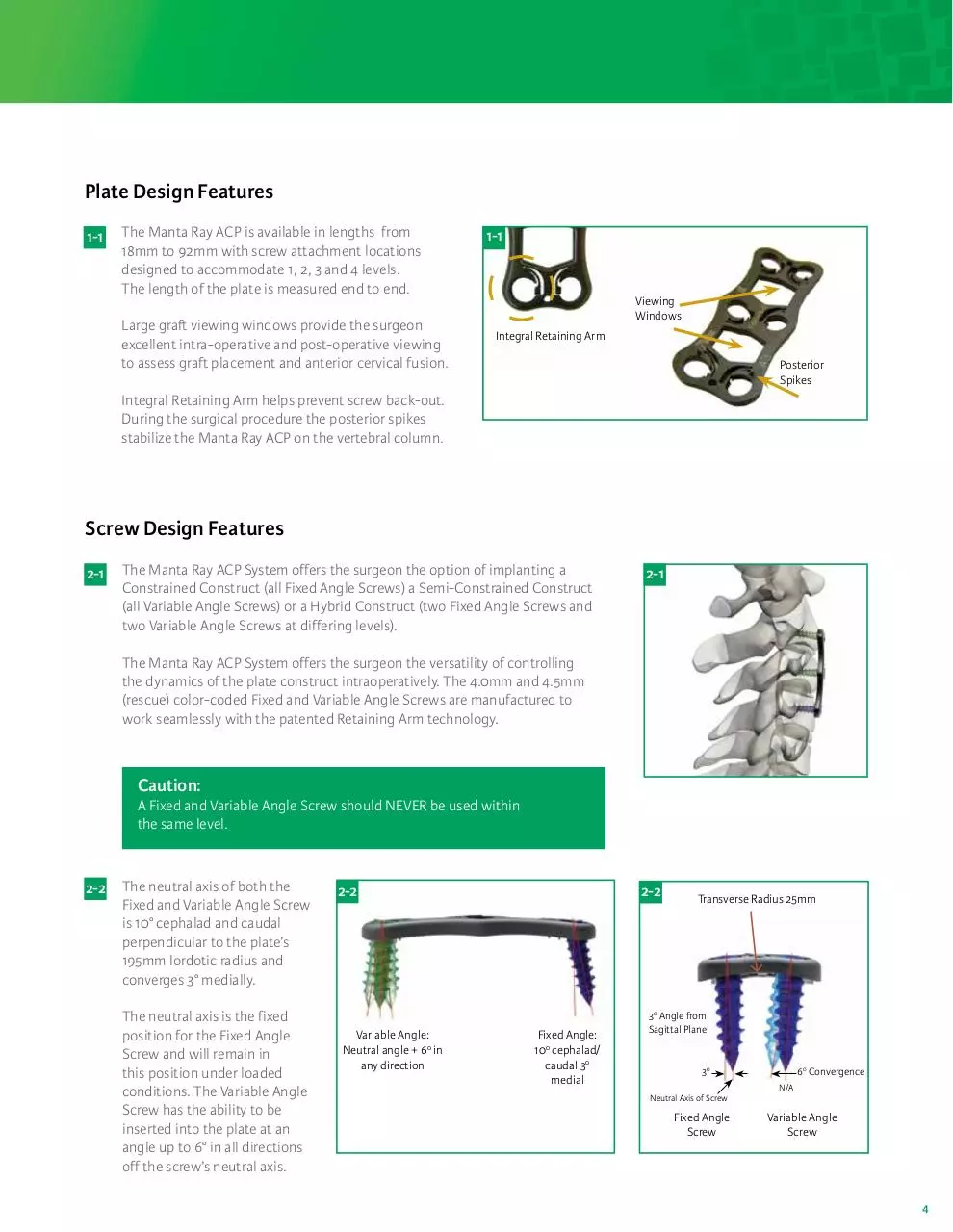
Plate Design Features
1-1
The Manta Ray ACP is available in lengths from
18mm to 92mm with screw attachment locations
designed to accommodate 1, 2, 3 and 4 levels.
The length of the plate is measured end to end.
Large graft viewing windows provide the surgeon
excellent intra-operative and post-operative viewing
to assess graft placement and anterior cervical fusion.
1-1
Viewing
Windows
Integral Retaining Arm
Posterior
Spikes
Integral Retaining Arm helps prevent screw back-out.
During the surgical procedure the posterior spikes
stabilize the Manta Ray ACP on the vertebral column.
Screw Design Features
2-1
The Manta Ray ACP System offers the surgeon the option of implanting a
Constrained Construct (all Fixed Angle Screws) a Semi-Constrained Construct
(all Variable Angle Screws) or a Hybrid Construct (two Fixed Angle Screws and
two Variable Angle Screws at differing levels).
2-1
The Manta Ray ACP System offers the surgeon the versatility of controlling
the dynamics of the plate construct intraoperatively. The 4.0mm and 4.5mm
(rescue) color-coded Fixed and Variable Angle Screws are manufactured to
work seamlessly with the patented Retaining Arm technology.
Caution:
A Fixed and Variable Angle Screw should NEVER be used within
the same level.
2-2
The neutral axis of both the
Fixed and Variable Angle Screw
is 10° cephalad and caudal
perpendicular to the plate’s
195mm lordotic radius and
converges 3° medially.
The neutral axis is the fixed
position for the Fixed Angle
Screw and will remain in
this position under loaded
conditions. The Variable Angle
Screw has the ability to be
inserted into the plate at an
angle up to 6° in all directions
off the screw’s neutral axis.
2-2
Variable Angle:
Neutral angle + 60 in
any direction
2-2
Fixed Angle:
100 cephalad/
caudal 30
medial
Transverse Radius 25mm
30 Angle from
Sagittal Plane
30
Neutral Axis of Screw
Fixed Angle
Screw
60 Convergence
N/A
Variable Angle
Screw
4
Plate Contouring
3-1
The 18mm through 92mm Manta Ray™ Plates are designed to be contoured
using the Plate Bender (22-40-0100). To contour the plate, insert the plate into
the Plate Bender while aligning the center of the graft viewing windows with
the Plate Bender.
3-1
Apply moderate pressure to the Plate Bender handles to increase or decrease
the plate curvature. Due to titanium’s inherent notch sensitivity, do not attempt
to decrease the plate curvature if it has been over-bent.
Warning:
Do not bend outside of this area as bending on or near a screw hole can
compromise the screw retaining mechanism.
Plate Holder
4-1
If using the Plate Holder (22-40-0800), attach the plate by
applying upward pressure on the spring loaded trigger, then
align the holding pin on the instrument with the hole on either
end of the plate. Release pressure from spring loaded trigger
and confirm that plate is securely attached to instrument before
inserting plate into the surgical wound.
4-1
Spring Loaded Trigger
To remove Plate Holder from plate, pull trigger and carefully
slide Plate Holder cephalad or caudal away from plate.
4-1
5
Plate Holding Technique
Position the plate so that the superior and inferior
holes are approximately at the mid-portion of the
vertebral body.
4-2
4-2 If using the optional Plate Holding Pins (22-40-0500),
attach the pins using the Screwdriver.
Insert the Plate Holding Pin on to the Screwdriver and
thread the pin into vertebral body.
4-3
Plate Holding Pins are used as follows:
Line up screwdriver with the hexalobe inside the Plate
Holding Pin. Use downward force to engage and retain
the Plate Holding Pin onto the driver.
4-3
Once the pin is engaged on the screwdriver, remove the
pin from the screw caddy by pulling upward.
Note:
The pin is now retained on the end of the screwdriver tip, and
should not come off in standard use. The pin is NOT locked on the
screwdriver, meaning with some deliberate force, the pin can be
pulled off the screwdriver.
Insert the Plate Holding Pin through the screw hole in the plate and
thread the pin into the vertebral body.
4-3
Note:
Over-tigh:tening the pin may result in stripping of the screw hole
and a loss of screw purchase to the bone.
To remove the Plate Holding Pin, insert the tip of the screwdriver
into the pin and unthread the pin out of the vertebral body in a
counterclockwise direction.
Option:
Plate Holding Pins are also available in a non-threaded style.
They are inserted by placing downward pressure on the driver.
6
Awl Use
5-1
Fixed & Variable Self-Centering Awl Use
Insert the Fixed (22-40-0600) or Variable (22-40-0650) Angle Awl into the
screw hole at the desired screw angle and push down while simultaneously
twisting the Awl handle.
Remove the Awl by pulling straight up while maintaining hole
and plate alignment.
Note:
Awl may be used with the standard 4.0mm or 4.5mm rescue screws.
5-1
5-1
Variable tip
Fixed tip
Drill Use (Optional For Self-Drilling Screws)
In some instances, the use of a Drill (22-40-0700) may
be preferred prior to screw insertion.
6-1
Fixed & Variable Self-Centering Drill Use
Choose either the Fixed Angle Drill Guide (22-40-0425),
Variable Angle Drill Guide (22-40-0475) or Double Barrel
Cannula (22-40-0480).
6-1
Set desired drill depth by depressing button and sliding
the depth stop to the proper depth.
6-2
Insert the Drill through the Guide. Engage the Drill into
the cortex of the vertebral body by turning the Drill
handle in a clockwise direction.
Once the stop on the Guide is reached, the Drill is now
at the appropriate depth. Remove the Drill from the
vertebral body by turning the Drill counter clockwise.
Note:
Drill may be used for the standard 4.0mm or
4.5mm rescue screws.
7
6-2
5-1
Tap Use (Optional)
In some instances, the use of a Tap (22-40-0750) may
be preferred prior to screw insertion.
7-1
7-1
Choose either the Fixed or Variable Angle Drill Guide.
Set depth.
7-2
Insert the Tap through the Guide. Engage the Tap into
the cortex of the vertebral body by turning the Tap
handle in a clockwise direction.
Once the stop on the Guide is reached, turn the Tap
handle counterclockwise to remove the Tap from the
vertebral body.
Note:
Note:
Taps should be
checked prior to each
surgery to ensure that
they are sharp.
Tap may be used for
the 4.0mm or 4.5mm
rescue screws.
7-2
Screw Verification
Screws are color-coded based on the screw diameter
and variability.
8-1
4.0mm FIXED: Light Blue
4.5mm FIXED RESCUE: Gold
4.0mm VARIABLE: Green
4.5mm VARIABLE RESCUE: Magenta
8-1
With the Fixed or Variable Angle Screw attached to the end of
the screwdriver, the screw length and diameter can be verified
using the Screw Gauge located on the Screw Caddy cover.
Note:
4.5mm diameter screws are “rescue screws” and should
only be used when 4.0mm diameter screws do not provide
enough purchase to the bone.
8
Download 0023637 Manta Ray ST
0023637_Manta Ray ST .pdf (PDF, 1.14 MB)
Download PDF
Share this file on social networks
Link to this page
Permanent link
Use the permanent link to the download page to share your document on Facebook, Twitter, LinkedIn, or directly with a contact by e-Mail, Messenger, Whatsapp, Line..
Short link
Use the short link to share your document on Twitter or by text message (SMS)
HTML Code
Copy the following HTML code to share your document on a Website or Blog
QR Code to this page

This file has been shared publicly by a user of PDF Archive.
Document ID: 0000383070.