DigitalAudio192 (PDF)
File information
Title: Microsoft Word - Digital Audio Series, 28-192KHz, Rev 2.doc
Author: Linda
This PDF 1.3 document has been generated by PScript5.dll Version 5.2 / Acrobat Distiller 5.0.5 (Windows), and has been sent on pdf-archive.com on 19/06/2016 at 14:12, from IP address 80.147.x.x.
The current document download page has been viewed 517 times.
File size: 233.19 KB (2 pages).
Privacy: public file

File preview
Digital Audio Interface Transformer
For Sampling Rates 28KHz to 192KHz
Functions of Transformer:
- Isolation of the system power return from ground loops
- Impedance matching between Driver and Receiver
- DC blocking
- Common Mode Noise and EMI rejection
- High frequency rejection
Features:
- Works with transmitter ICs: Cirrus Logic (Crystal), Rane,
TI/Burr-Brown, AKM, Yamaha, Wolfram, etc.
- Works in ambient temperature: 0°C to 70°C
Applications
Connections
Between
RCA
RCA
BNC
BNC
XLR
XLR
Line
Digital
Audio
Interface
Unbalanced
SPDIF
Differences Between Interfaces
Impeda
nce
Ratio
XFMR
Turns
Ratio
AES3
110:100
Balanced
XLR-3
Unbalanced
BNC
Unbalanced
RCA
Impedance
Ω
110
75
75
1:1
Output Level
Vp-p
2-7
1.0
0.5
Max Output
V
Vp-p
7
1.2
0.6
Max Current
mA
64
1.6
8
Min Input
V
0.2
0.32
0.2
STP
Coax
Coax
100
1000
10
Trans
mitter
XLR
Balanced
AES3
110:110
1:1
Trans
mitter
RCA
Unbalanced
SPDIF
300:75
2:1
XLR
RCA
110:75
1.21:1
BNC
AE-3id
BalancedUnbalanced
BNC
From AES3
To SPDIF
SPDIF
Unit
AE-3id
Balanced
AES-3id
Line
Connector
1:1
75:75
AES3
Cable
Max Distance
m
Requirements for Transformer
Sampling Rate
32KHz
Sampling Rate Versus Bandwidth
Sampling Rate
(KHz)
28
32
48
96
192
Pass Range
(-1dB Max)
Low Cut-off
Frequency
High Cut-off
Frequency
Bandwidth (-3dB)
(MHz)
3.6
4.1
6.2
12.3
24.6
(MHz)
Max.
(MHz)
Min.
(MHz)
0.3
0.4
0.6
1.2
2.5
40
50
70
130
250
Vo/Vi
(dB)
28KHz
96KHz
48KHz
192KHz
0
-1
-3
0.3-250
0.3
3.6
Bandwidth
6.1
4.1
24.6
12.3
250
F
(MHz)
Electrical Specifications @25°C
Schott
P/N
Turns
Ratio
OCL
(Cable Side)
uH Min.
LL
IWC
DCR
DCR
uH Max.
pF Max
Ω ± 20%
Ω± 20%
Style
Foot Print
#
A22083
1:1
225
0.2
100
0.44
0.44
T case
4 Pin THD
5
A22133
1:1
225
0.2
20
0.12
0.12
ER9.5
6 Pin THD
4
A22160
1:1
225
0.2
100
0.12
0.12
ER9.5
6 Pin THD
1
A22523
1:1.22
225
0.2
20
0.12
0.15
ER9.5
6 Pin THD
4
Shield,
75Ω:100Ω
A24393
1:3
225
0.2
100
0.14
0.43
ER9.5
6 Pin THD
1
Higher Voltage
A37211
1:1
225
0.2
100
0.12
0.12
ER9.5
8 Pin SMD
2
A37246
1:1
225
0.2
20
0.12
0.12
ER9.5
8 Pin SMD
3
A1001
1:2
225
0.2
100
0.12
0.24
ER9.5
8 Pin SMD
6
Schott Magnetics - Tacna International Corp.
210 N. Saint Olaf, Canby, MN 56220
(507) 223-5572
Package
Website: www.SchottMagnetics.com
Schematic
Specialty
Shield
5/21/09 Rev 2
Page 1
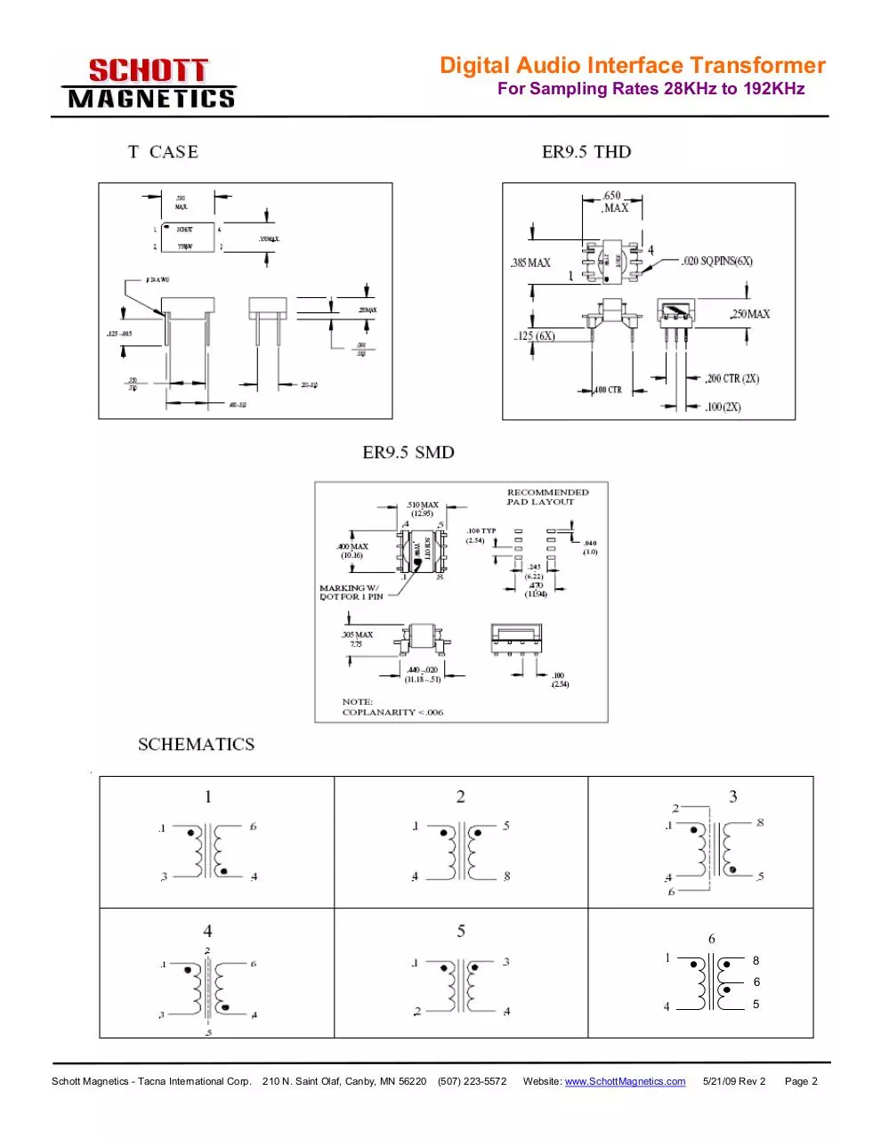
Digital Audio Interface Transformer
For Sampling Rates 28KHz to 192KHz
6
1
58
6
4
Schott Magnetics - Tacna International Corp.
210 N. Saint Olaf, Canby, MN 56220
(507) 223-5572
Website: www.SchottMagnetics.com
85
5/21/09 Rev 2
Page 2
Download DigitalAudio192
DigitalAudio192.pdf (PDF, 233.19 KB)
Download PDF
Share this file on social networks
Link to this page
Permanent link
Use the permanent link to the download page to share your document on Facebook, Twitter, LinkedIn, or directly with a contact by e-Mail, Messenger, Whatsapp, Line..
Short link
Use the short link to share your document on Twitter or by text message (SMS)
HTML Code
Copy the following HTML code to share your document on a Website or Blog
QR Code to this page

This file has been shared publicly by a user of PDF Archive.
Document ID: 0000390281.