tech3250 (PDF)
File information
Title: EBU Tech 3250-2004 Specification of the digital audio interface (AES/EBU)
Author: EBU
This PDF 1.5 document has been generated by Microsoft Word - tec_doc_t3250-2004.doc / Acrobat PDFWriter 5.0 for Windows NT, and has been sent on pdf-archive.com on 19/06/2016 at 12:22, from IP address 80.147.x.x.
The current document download page has been viewed 636 times.
File size: 126.59 KB (20 pages).
Privacy: public file

File preview
SPECIFICATION OF THE DIGITAL AUDIO INTERFACE
(The AES/EBU interface)
Tech. 3250-E - Third edition
2004
CONTENTS
1.
2.
Scope ...................................................................................................................................................................2
Interface format....................................................................................................................................................2
2.1.
Terminology.................................................................................................................................................2
2.2.
Structure of format........................................................................................................................................3
2.3.
Channel coding.............................................................................................................................................5
2.4.
Preambles .....................................................................................................................................................5
2.5.
Validity bit ...................................................................................................................................................6
3.
User data format...................................................................................................................................................6
4.
Channel status format ...........................................................................................................................................6
5.
6.
Interface format implementation .........................................................................................................................12
5.1.
General.......................................................................................................................................................12
5.2.
Transmitter .................................................................................................................................................12
5.3.
Receivers....................................................................................................................................................13
Electrical requirements .......................................................................................................................................13
6.1.
General characteristic..................................................................................................................................13
6.2.
Line driver characteristics ...........................................................................................................................14
6.3.
Line receiver characteristics ........................................................................................................................15
6.4.
Connectors .................................................................................................................................................16
Appendix 1 Generation of the CRCC (Byte 23) for channel status...............................................................................17
Appendix 2 AES/EBU signals on Structured Wiring...................................................................................................19
Bibliography..............................................................................................................................................................20
European Broadcasting Union
Ancienne Route 17A, CH-1218 Grand-Saconnex (Geneva) Switzerland
tech 3250
EBU - Specification of the digital audio interface
Specification of the digital audio interface
(The AES/EBU interface)
1.
Scope
This document specifies a recommended interface for the serial digital transmission of two channels of
periodically sampled and linearly represented digital audio data in a broadcasting complex, up to a distance of a few
hundred metres,
Although this transmission specification is independent of sampling frequency it is intended that the interface
be primarily used at 48 kHz, as this is the recommended sampling frequency for use in broadcasting studios (CCIR
Recommendation 646).
The document does not cover connection to any common carrier equipment nor does it specifically address any
of the questions relating to the synchronising of large systems, although by its nature the format permits easy
synchronisation of receiving devices to the transmitting device.
Specific synchronisation issues are covered in document AES 1l-l991.
Note 1: In this interface specification for broadcasting studio use, mention is also made of an interface for
consumer use. The two interfaces are not identical.
Note 2: An engineering guideline document to accompany this interface specification is in course of
preparation by the EBU.
2.
Interface format
2.1.
Terminology
For the purpose of this specification the following definitions of terms apply.
2.1.1.
Sampling Frequency
The sampling frequency is the frequency of the samples representing an audio signal. When more than one
audio signal is transmitted through the same interface, the sampling frequencies shall be identical.
2.1.2.
Audio sample word
The audio sample word represents the amplitude of a digital audio sample. Representation is linear in 2's
complement binary form. Positive numbers correspond to positive analogue voltages at the input of the analogue to
digital converter (ADC). The number of bits per word can be specified from 16 to 24 in two coding ranges (less than or
equal to 20 bits and less than or equal to 24 bits).
2.1.3.
Auxiliary sample bits
The four least significant bits (LSB) can be assigned as auxiliary sample bits and used for auxiliary information
when the number of audio sample bits is less than or equal to 20.
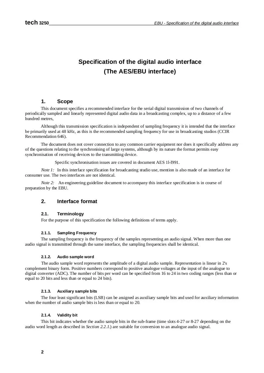
2.1.4.
Validity bit
This bit indicates whether the audio sample bits in the sub-frame (time slots 4-27 or 8-27 depending on the
audio word length as described in Section 2.2.1.) are suitable for conversion to an analogue audio signal.
2
EBU - Specification of the digital audio interface
2.1.5.
tech 3250
Channel status
The channel status carries, in a fixed format derived from the block (see Section 2. 1. 11.), information
associated with each audio channel, which is decodable by any interface user.
2.1.6.
User data
The user data channel is provided to carry any other information.
2.1.7.
Parity bit
The parity bit is provided to permit the detection of an odd number of errors resulting from malfunctions in the
interface.
2.1.8.
Preambles
Preambles are specific patterns used for synchronisation. There are three different preambles (see Section 2.4.).
2.1.9.
Sub-frame
The sub-frame is a fixed structure used to carry the information described in Sections 2.1.1. to 2.1.8. (See
Sections 2.2.1. and 2.2.2.).
2.1.10. Frame
The frame is a sequence of two successive and associated sub-frames.
2.1.11. Block
The block is a group of 192 consecutive frames. The start of a block is designated by a special sub-frame
preamble (see Section 2.4.).
2.1.12. Channel coding
The channel coding describes the method by which the binary digits are represented for transmission through
the interface.
2.1.13. Unit interval UI
Shortest nominal time interval in the coding scheme
2.1.14. Interface jitter
Deviation in timing of interface data transitions (zero crossings) when measured with respect to an ideal clock
2.1.15. Intrinsic jitter
Output interface jitter of a device that is either free running or is synchronized to a jitter-free reference
2.1.16. Jitter gain
Rate of transmission of frames
2.2.
Structure of format
2.2.1.
Sub-frame format
Each sub-frame is divided into 32 time slots, numbered from 0 to 31 (see fig 1)
Time slots 0 to 3 (preamble) carry one of the three permitted preambles (see Fig. 2) (see Sections 2.2.2. and
2.4; see also Fig. 2).
Time slots 4 to 27 (audio samples word) carry the audio sample word in linear 2's complement representation.
The most significant bit (MSB) is carried by time slot 27.
When a 24-bit coding range is used, the LSB is in time slot 4 (see Fig. 1a).
3
tech 3250
EBU - Specification of the digital audio interface
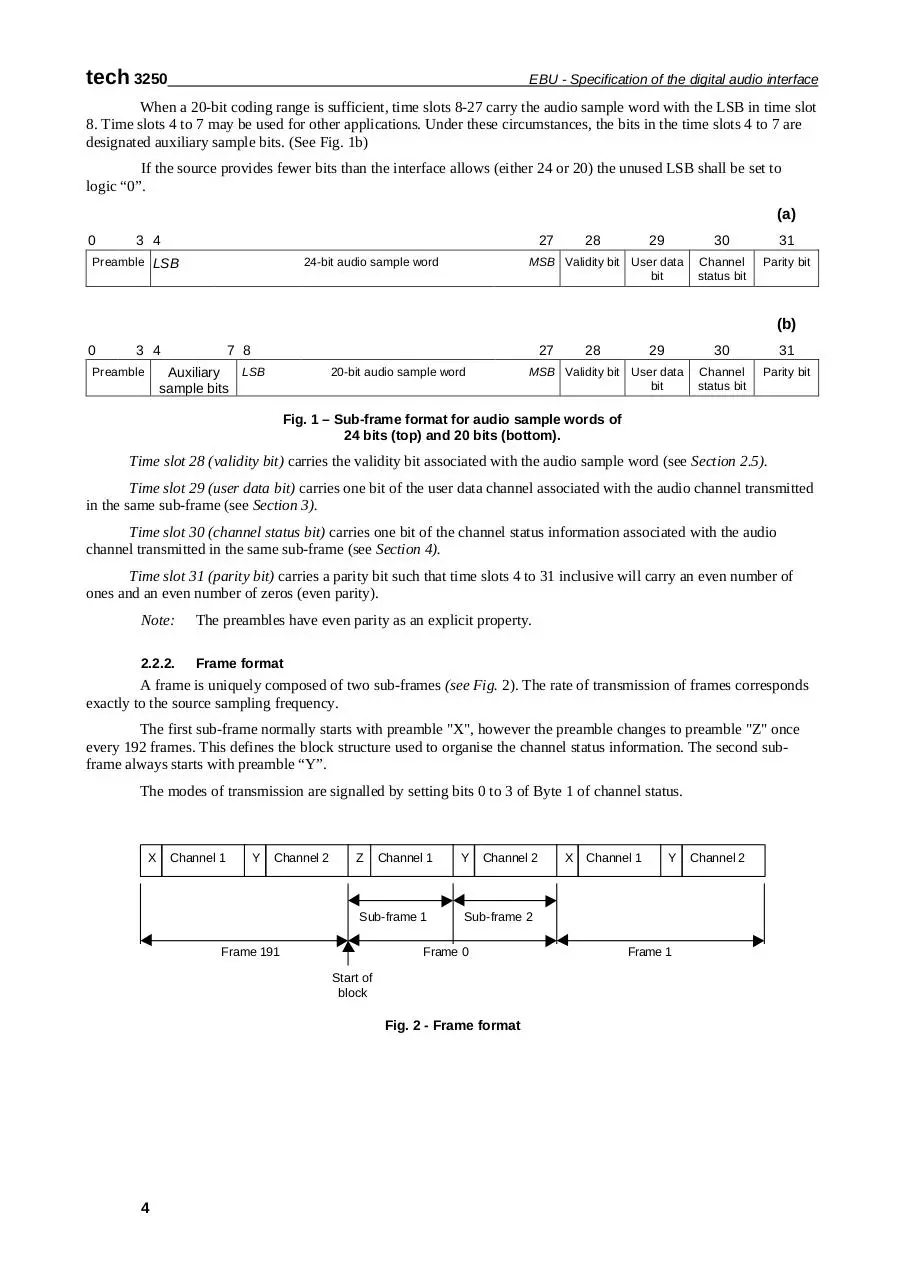
When a 20-bit coding range is sufficient, time slots 8-27 carry the audio sample word with the LSB in time slot
8. Time slots 4 to 7 may be used for other applications. Under these circumstances, the bits in the time slots 4 to 7 are
designated auxiliary sample bits. (See Fig. 1b)
If the source provides fewer bits than the interface allows (either 24 or 20) the unused LSB shall be set to
logic “0”.
(a)
0
3 4
27
Preamble LSB
28
29
MSB Validity bit User data
bit
24-bit audio sample word
30
31
Channel
status bit
Parity bit
(b)
0
3 4
7 8
27
LSB
Auxiliary
sample bits
Preamble
28
29
MSB Validity bit User data
bit
20-bit audio sample word
30
31
Channel
status bit
Parity bit
Fig. 1 – Sub-frame format for audio sample words of
24 bits (top) and 20 bits (bottom).
Time slot 28 (validity bit) carries the validity bit associated with the audio sample word (see Section 2.5).
Time slot 29 (user data bit) carries one bit of the user data channel associated with the audio channel transmitted
in the same sub-frame (see Section 3).
Time slot 30 (channel status bit) carries one bit of the channel status information associated with the audio
channel transmitted in the same sub-frame (see Section 4).
Time slot 31 (parity bit) carries a parity bit such that time slots 4 to 31 inclusive will carry an even number of
ones and an even number of zeros (even parity).
Note:
The preambles have even parity as an explicit property.
2.2.2.
Frame format
A frame is uniquely composed of two sub-frames (see Fig. 2). The rate of transmission of frames corresponds
exactly to the source sampling frequency.
The first sub-frame normally starts with preamble "X", however the preamble changes to preamble "Z" once
every 192 frames. This defines the block structure used to organise the channel status information. The second subframe always starts with preamble “Y”.
The modes of transmission are signalled by setting bits 0 to 3 of Byte 1 of channel status.
X
Channel 1
Y
Channel 2
Z
Channel 1
Sub-frame 1
Frame 191
Y
Channel 2
Channel 1
Y
Sub-frame 2
Frame 0
Start of
block
Fig. 2 - Frame format
4
X
Frame 1
Channel 2
tech 3250
EBU - Specification of the digital audio interface
Clock
(2 times bit rate)
1
Source coding
0
1
Channel coding
(bi-phase mark)
0
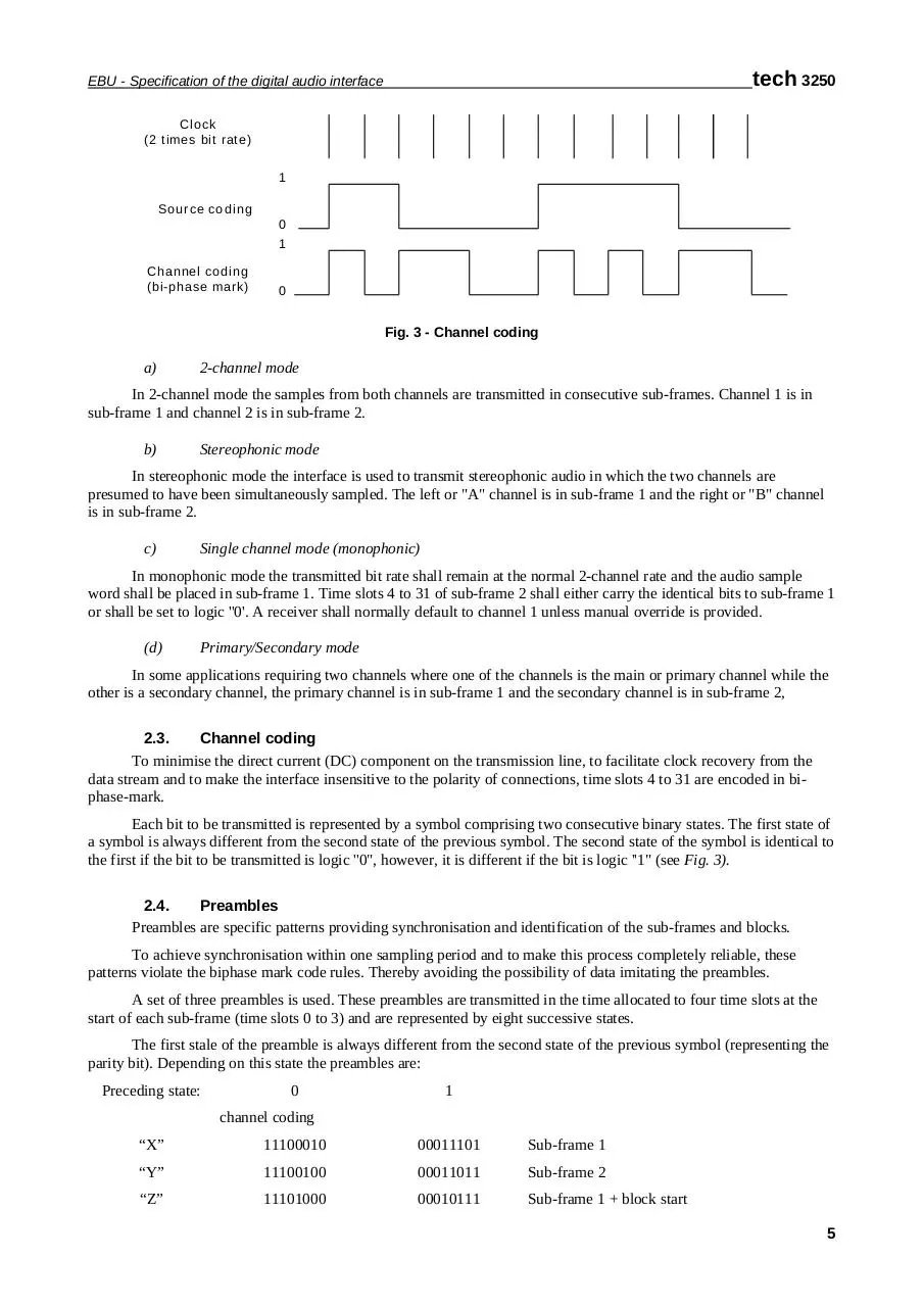
Fig. 3 - Channel coding
a)
2-channel mode
In 2-channel mode the samples from both channels are transmitted in consecutive sub-frames. Channel 1 is in
sub-frame 1 and channel 2 is in sub-frame 2.
b)
Stereophonic mode
In stereophonic mode the interface is used to transmit stereophonic audio in which the two channels are
presumed to have been simultaneously sampled. The left or "A" channel is in sub-frame 1 and the right or "B" channel
is in sub-frame 2.
c)
Single channel mode (monophonic)
In monophonic mode the transmitted bit rate shall remain at the normal 2-channel rate and the audio sample
word shall be placed in sub-frame 1. Time slots 4 to 31 of sub-frame 2 shall either carry the identical bits to sub-frame 1
or shall be set to logic ''0'. A receiver shall normally default to channel 1 unless manual override is provided.
(d)
Primary/Secondary mode
In some applications requiring two channels where one of the channels is the main or primary channel while the
other is a secondary channel, the primary channel is in sub-frame 1 and the secondary channel is in sub-frame 2,
2.3.
Channel coding
To minimise the direct current (DC) component on the transmission line, to facilitate clock recovery from the
data stream and to make the interface insensitive to the polarity of connections, time slots 4 to 31 are encoded in biphase-mark.
Each bit to be transmitted is represented by a symbol comprising two consecutive binary states. The first state of
a symbol is always different from the second state of the previous symbol. The second state of the symbol is identical to
the first if the bit to be transmitted is logic ''0", however, it is different if the bit is logic ''1" (see Fig. 3).
2.4.
Preambles
Preambles are specific patterns providing synchronisation and identification of the sub-frames and blocks.
To achieve synchronisation within one sampling period and to make this process completely reliable, these
patterns violate the biphase mark code rules. Thereby avoiding the possibility of data imitating the preambles.
A set of three preambles is used. These preambles are transmitted in the time allocated to four time slots at the
start of each sub-frame (time slots 0 to 3) and are represented by eight successive states.
The first stale of the preamble is always different from the second state of the previous symbol (representing the
parity bit). Depending on this state the preambles are:
Preceding state:
0
1
channel coding
“X”
11100010
00011101
Sub-frame 1
“Y”
11100100
00011011
Sub-frame 2
“Z”
11101000
00010111
Sub-frame 1 + block start
5
tech 3250
EBU - Specification of the digital audio interface
As with biphase code, these preambles are DC free and provide clock recovery. They differ in at least two states
from any valid biphase sequence.
Fig. 4 represents preamble "X".
Clock
1
1
1
0
0
0
1
Parity
0
LSB
Absence of transition at bit
boundary
Fig. 4 Preamble "X" (11100010)
Note: Owing to the even parity bit in time slot 31, all preambles will start with a transition in the same
direction (see Section 3.2.1.). Thus only one of these sets of preambles will, in practice, be transmitted through the
interface. However, it is necessary for either set to be decodable because a polarity reversal may occur in the
connection.
2.5.
Validity bit
The validity bit shall be logic “0” if the audio sample word is suitable for conversion to an analogue audio signal
and it shall be logic “1” if it is not.
There is no default state for the validity bit
3.
User data format
User data bits may be used in any way desired by the user.
Channel status Byte 1 bits 4-7 indicate possible formats for the user data channel.
The default value of the user data bit shall be logic "0".
4.
Channel status format
The channel status for each audio signal carries information associated with that audio signal, and thus it is
possible for different channel status data to be carried in the two sub-frames of the digital audio signal. Examples of
information to be carried in the channel status are: length of audio sample words, number of audio channels, sampling
frequency, time code, alphanumeric source and destination codes, and pre-emphasis.
Channel status information is organised in 92-bit blocks, subdivided into 24 Bytes (Fig. 5). The first bit of each
block is carried in the Frame with preamble "Z".
The specific organisation follows, wherein the suffix 0 designates the first Byte or bit. Where multiple bit
states represent a counting number, tables are arranged with most significant bit (MSB) first, except where noted as
LSB first.
6
tech 3250
EBU - Specification of the digital audio interface
Bit
Byte
0
1
0
Use of
channel
status
channel
Linear PCM
identification
1
2
2
3
4
5
5
Audio signal pre-emphasis
6
User bit management
Use of auxiliary sample bits
Source word length & source encoding
history
Indication of alignment level
Channel number
N=0
Channel number
Digital audio reference
7
Sampling frequency
Locking of
source
sample
frequency
Channel mode
3
3
4
Multichannel mode number
Reserved
Sampling frequency
N=1
SF scaling
flag
Reserved
6
7
Alphanumeric channel origin data
8
9
10
11
Alphanumeric channel destination data
12
13
14
15
Local sample address code (32-bit binary)
16
17
18
19
Time-of-day sample address code (32-bit binary)
20
21
22
Reliability flags
23
Cyclic redundancy check character
Fig. 5 - Channel status data format
7
tech 3250
EBU - Specification of the digital audio interface
Byte 0
Bit 0
0
Consumer use of channel status block (see Note)
1
Professional use of channel status block
0
Audio sample word represents linear PCM samples
1
Audio sample words used for purposes other then linear PCM samples
Bit 1
Bits 2 to 4
bit
2
0
1
1
1
3
0
0
1
1
Encoded audio signal emphasis
4
0
0
0
1
Emphasis not indicated. Receiver defaults to no emphasis with manual over-ride enabled.
No emphasis. Receiver manual over-ride disabled.
50/15 µs emphasis. Receiver manual over-ride disabled.
CCITT J.17 emphasis (with 6.5 dB insertion loss at 500 Hz). Receiver manual over-ride disabled.
All other states of bits 2-4 are reserved and are not to be used until further defined.
Bit 5
0
1
Bits 6 to 7
bit
Default, and source sampling frequency locked.
Source sampling frequency unlocked.
Encoded sampling frequency
6
7
0
0
Sampling freq. not indicated. Receiver defaults to interface frame rate and manual over-ride or auto set enabled.
0
1
48 kHz sampling frequency. Manual over-ride or auto set disabled.
1
0
44.1 kHz sampling frequency. Manual over-ride or auto set disabled.
1
1
32 kHz sampling frequency. Manual over-ride or auto set disabled.
Note 1:
The significance of Byte 0 bit 0 is such that a transmission from an interface conforming to IEC 60958-3 "consumer use” can be
identified, and receiver conforming only to IEC 60958-3 "consumer use" will correctly identify a transmission from a "professional
use" interface as defined in this standard. Connection of a "professional use" transmitter with a "consumer use receiver or vice versa
might result in unpredictable operation. Thus the following Byte definitions only apply when bit 0 = logic 1 (professional use of the
channel status block).
Note 2:
The indication of sampling frequency, or the use of one of the sampling frequencies that can be indicated in this Byte, is not a
requirement for operation of the interface. The 0 0 state of bits 6 and 7 may be used if the transmitter does not support the indication of
sampling frequency, the sampling frequency is unknown, or the sample frequency is not one of those that can be indicated in this Byte.
In the letter case for some sampling frequencies Byte 4 may be used to indicate the correct value.
Note 3:
When Byte 1, bits 1 to 3 indicate single channel double sampling frequency mode then the sampling frequency of the audio signal is
twice that indicated by bits 6 to 7 of Byte 0.
8
tech 3250
EBU - Specification of the digital audio interface
Byte 1
Bits 0 to 3
Encoded channel mode
bit 0
1
2
3
0
0
0
0
Mode not indicated. Receiver default to two-channel mode. Manual over-ride enabled.
0
0
0
1
Two-channel mode. Manual over-ride disabled.
0
0
1
0
Single-channel mode (monophonic). Manual over-ride disabled.
0
0
1
1
Primary - secondary mode (sub-frame 1 is primary). Manual over-ride disabled.
0
1
0
0
Stereophonic mode (channel 1 is left channel). Manual over-ride disabled.
0
1
0
1
Reserved for user-defined applications.
0
1
1
0
Reserved for user-defined applications.
0
1
1
1
Single channel double sampling frequency mode. Sub frames 1 and 2 carry successive samples of the same
signal. The sampling frequency of the signal is double the frame rate, and is double the rate indicated in Byte 0, but
not double the rate indicated in Byte 4, if that is used. Manual override is disabled. Vector to Byte 3 for channel
identification.
1
0
0
0
Single channel double sampling frequency mode – stereo mode left. Sub frames 1 an 2 carry successive samples
of the same signal. The sampling frequency of the signal is double the frame rate, and is double the rate indicated
in Byte 0, but not double the rate indicated in Byte 4, if that is used. Manual override is disabled.
1
0
0
1
Single channel double sampling frequency mode – stereo mode right. Sub frames 1 an 2 carry successive samples
of the same signal. The sampling frequency of the signal is double the frame rate, and is double the rate indicated
in Byte 0, but not double the rate indicated in Byte 4, if that is used. Manual override is disabled.
1
1
1
1
Multichannel mode. Vector to Byte 3. Reserved for future applications.
All other states of bits 0 to 3 are reserved and are not to be used until further defined.
Bits 4 to 7
bit 4
0
0
0
0
0
0
Note:
5
0
0
0
0
1
1
6
0
0
1
1
0
0
Encoded user bits management
7
0 Default. No user information indicated.
1 1 92~bit block structure. Preamble "Z" indicates the start of a block.
0 Packet system based on HDLC protocol (see Note).
1 User defined.
0 Use data conforms to the general user data format defined in IEC 60958-3.
1 Reserved for Metadata
All other states of bits 4 to 7 are reserved and are not to be used until further defined.
This system is defined in Supplement 1 to EBU Tech. 3250: format of the user data channel of the digital audio interface.
9
Download tech3250
tech3250.pdf (PDF, 126.59 KB)
Download PDF
Share this file on social networks
Link to this page
Permanent link
Use the permanent link to the download page to share your document on Facebook, Twitter, LinkedIn, or directly with a contact by e-Mail, Messenger, Whatsapp, Line..
Short link
Use the short link to share your document on Twitter or by text message (SMS)
HTML Code
Copy the following HTML code to share your document on a Website or Blog
QR Code to this page

This file has been shared publicly by a user of PDF Archive.
Document ID: 0000390238.