Technical Attachment (PDF)
File information
This PDF 1.6 document has been generated by , and has been sent on pdf-archive.com on 16/11/2016 at 16:15, from IP address 104.38.x.x.
The current document download page has been viewed 612 times.
File size: 4.66 MB (102 pages).
Privacy: public file


File preview
SPACEX NON-GEOSTATIONARY SATELLITE SYSTEM
ATTACHMENT A
TECHNICAL INFORMATION TO SUPPLEMENT SCHEDULE S
A.1
SCOPE AND PURPOSE
This attachment contains the information required under Part 25 of the Commission’s
rules that cannot be fully captured by the associated Schedule S.
A.2
OVERALL DESCRIPTION
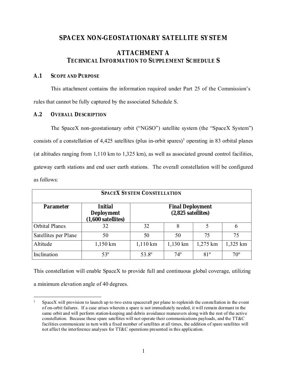
The SpaceX non-geostationary orbit (“NGSO”) satellite system (the “SpaceX System”)
consists of a constellation of 4,425 satellites (plus in-orbit spares)1 operating in 83 orbital planes
(at altitudes ranging from 1,110 km to 1,325 km), as well as associated ground control facilities,
gateway earth stations and end user earth stations. The overall constellation will be configured
as follows:
SPACEX SYSTEM CONSTELLATION
Parameter
Orbital Planes
Satellites per Plane
Altitude
Inclination
Initial
Deployment
(1,600 satellites)
32
Final Deployment
(2,825 satellites)
32
8
5
6
50
50
50
75
75
1,150 km
1,110 km
1,130 km
1,275 km
1,325 km
53º
53.8º
74º
81º
70º
This constellation will enable SpaceX to provide full and continuous global coverage, utilizing
a minimum elevation angle of 40 degrees.
1
SpaceX will provision to launch up to two extra spacecraft per plane to replenish the constellation in the event
of on-orbit failures. If a case arises wherein a spare is not immediately needed, it will remain dormant in the
same orbit and will perform station-keeping and debris avoidance maneuvers along with the rest of the active
constellation. Because these spare satellites will not operate their communications payloads, and the TT&C
facilities communicate in turn with a fixed number of satellites at all times, the addition of spare satellites will
not affect the interference analyses for TT&C operations presented in this application.
1
The system is designed to provide a wide range of broadband and communications
services for residential, commercial, institutional, governmental and professional users
worldwide. Advanced phased array beam-forming and digital processing technologies within the
satellite payload give the system the ability to make highly efficient use of Ku- and Ka-band
spectrum resources and the flexibility to share that spectrum with other licensed users. User
terminals operating with the SpaceX System will use similar phased array technologies to allow
for highly directive, steered antenna beams that track the system’s low-Earth orbit satellites.
Gateway earth stations also apply advanced phased array technologies to generate high-gain
steered beams to communicate with multiple NGSO satellites from a single gateway site. The
system will also employ optical inter-satellite links for seamless network management and
continuity of service, which will also aid in complying with emissions constraints designed to
facilitate spectrum sharing with other systems.
The frequency ranges used by the SpaceX System are summarized in Table A.2-1 below.
Figure A.2-1 depicts the spectrum used for gateway and user beams and for telemetry, tracking,
and control (“TT&C”) operations, along with an indication of the U.S. frequency allocations and
designations that exist in these bands. The detailed channelized frequency plan is provided in the
associated Schedule S.
2
Type of Link and Transmission
Direction
Frequency Ranges
User Downlink
Satellite-to-User Terminal
10.7 – 12.7 GHz
Gateway Downlink
Satellite to Gateway
17.8 – 18.6 GHz
18.8 – 19.3 GHz
User Uplink
User Terminal to Satellite
14.0 – 14.5 GHz
Gateway Uplink
Gateway to Satellite
27.5 – 29.1 GHz
29.5 – 30.0 GHz
TT&C Downlink
12.15 – 12.25 GHz
18.55 – 18.60 GHz
TT&C Uplink
13.85 – 14.00 GHz
Table A.2-1: Frequency Bands Used by the SpaceX System
3
4
SpaceX recognizes that not all of the frequencies that it proposes to use are designated in the
United States for use by NGSO FSS systems on a primary basis. As discussed below, SpaceX
believes that its system can operate without causing harmful interference to or requiring
protection from any other service duly licensed in these bands with higher priority.2
A.3
PREDICTED SPACE STATION ANTENNA GAIN CONTOURS
All satellites in the SpaceX System have been designed with the same transmit and
receive antenna beams. The antenna gain contours for the transmit and receive beams for a
representative space station are embedded in the associated Schedule S, as required by Section
25.114(c)(4)(vi)(B). The contours for all transmit and receive beams are essentially the same for
satellites operating in all planes and altitudes. Below we describe the methodology for their
presentation in the associated Schedule S.
A.3.1 Ku-Band User Beams
All Ku-band downlink spot beams on each SpaceX satellite are independently steerable
over the full field of view of the Earth. However, user terminals at the customers’ premises
communicate only with satellites at an elevation angle of at least 40 degrees. Consequently, as
shown in Figure A.3.1-1 below, each satellite operating at an altitude of 1,150 km will provide
service only up to 40.46 degrees away from boresight (nadir), covering an area of about 3.5
million square kilometers (1,060 km radius).3
2
Where appropriate, SpaceX has requested waivers for non-conforming use of spectrum.
3
While the 40 degree minimum elevation angle remains the same from the earth station point of view, the
maximum angle from boresight at which service can be provided from the satellite changes slightly depending
upon altitude. Thus, satellites operating at 1,110 km, 1,130 km, 1,275 km, and 1,325 km altitude can provide
service up to 40.72, 40.59, 39.67, and 39.36 degrees away from boresight, respectively.
5
Figure A.3.1-1: Steerable Service Range of Ku-band Beams (1,150 km)
Generally, beams from antennas using phased arrays widen incrementally as they are
steered away from boresight.4 However, this widening occurs only in the plane formed by
boresight and the center of the beam (“elevation”), and not in the plane normal to that plane
formed by boresight and the center of the beam (“azimuth”). As a result, the shape of a phased
array beam at boresight is circular but becomes increasingly elliptical when steered away from
boresight.
This beam widening behavior with phased array antennas creates several effects that must
be offset in order to achieve efficient use of spectrum through frequency re-use. As the beam
widens, the size of the spot on the ground increases due to the increased distance to the Earth’s
surface, and the curvature of the Earth enhances this effect. For transmitting antennas, this
results in transmission of radiofrequency energy over a wider area, which increases both the
potential to interfere with other systems and the potential for interference with other beams of the
SpaceX System using the same frequencies. Conversely, for receiving antennas, this results in
4
For this purpose, we use “boresight” to refer to the direction normal to the phased array plane.
6
reception of radiofrequency energy from a wider area, which increases both the susceptibility to
interference from other systems and the potential for self-interference from user terminal uplink
transmissions.
The SpaceX System offsets these beamwidth variations by switching antenna elements in
the phased array on and off at certain steering angles.
By ensuring that radio energy is
transmitted in the desired direction, this switching helps to mitigate interference with other
systems. Specifically, as shown in Figure A.3.1-2 below, additional elements are turned on
when the angle reaches 23 degrees, and then again when it reaches 32 degrees. (Note this
applies for both transmit and receive antennas on each satellite.)
Figure A.3.1-2: Beamwidth Variation at Various Steering Angles
The following figures illustrate this dynamic by plotting antenna gain contours (for both uplink
and downlink beams) at key steering angles, in each case at a roll off of -2 dB, -4 dB, -6 dB, -8
dB, -10 dB, -15 dB, and -20 dB.
Figure A.3.1-3 shows the antenna gain contour with the beam pointed to nadir (boresight,
or zero steering angle).
7
Figure A.3.1-5 shows the same plot, but after additional elements of the phased array antenna
have been turned on to reduce beamwidth.
Figure A.3.1-5: Beam Contour at 23 Degrees Elevation
After Additional Elements Turned ON
Similarly, Figures A.3.1-6 and A.3.1-7 below show the same beam when it has been steered to
32 degrees, first without the additional elements turned on and then with them turned on to
reduce beamwidth.
9
Download Technical Attachment
Technical Attachment.pdf (PDF, 4.66 MB)
Download PDF
Share this file on social networks
Link to this page
Permanent link
Use the permanent link to the download page to share your document on Facebook, Twitter, LinkedIn, or directly with a contact by e-Mail, Messenger, Whatsapp, Line..
Short link
Use the short link to share your document on Twitter or by text message (SMS)
HTML Code
Copy the following HTML code to share your document on a Website or Blog
QR Code to this page

This file has been shared publicly by a user of PDF Archive.
Document ID: 0000508133.