1993 transaxle assembly removal camry (PDF)
File information
Title: R.M. 1993::A540e Automatic Transaxle: Assembly Removal And Installation (CAMRY)
This PDF 1.4 document has been generated by / Qt 4.6.1 (C) 2009 Nokia Corporation and/or its subsidiary(-ies), and has been sent on pdf-archive.com on 22/11/2016 at 17:31, from IP address 67.149.x.x.
The current document download page has been viewed 881 times.
File size: 1.62 MB (14 pages).
Privacy: public file


File preview
1993 Toyota CAMRY
Submodel: LE | Engine Type: V6 | Liters: 3.0
Fuel Delivery: FI | Fuel: GAS
ASSEMBLY REMOVAL AND
INSTALLATION
ASSEMBLY COMPONENTS
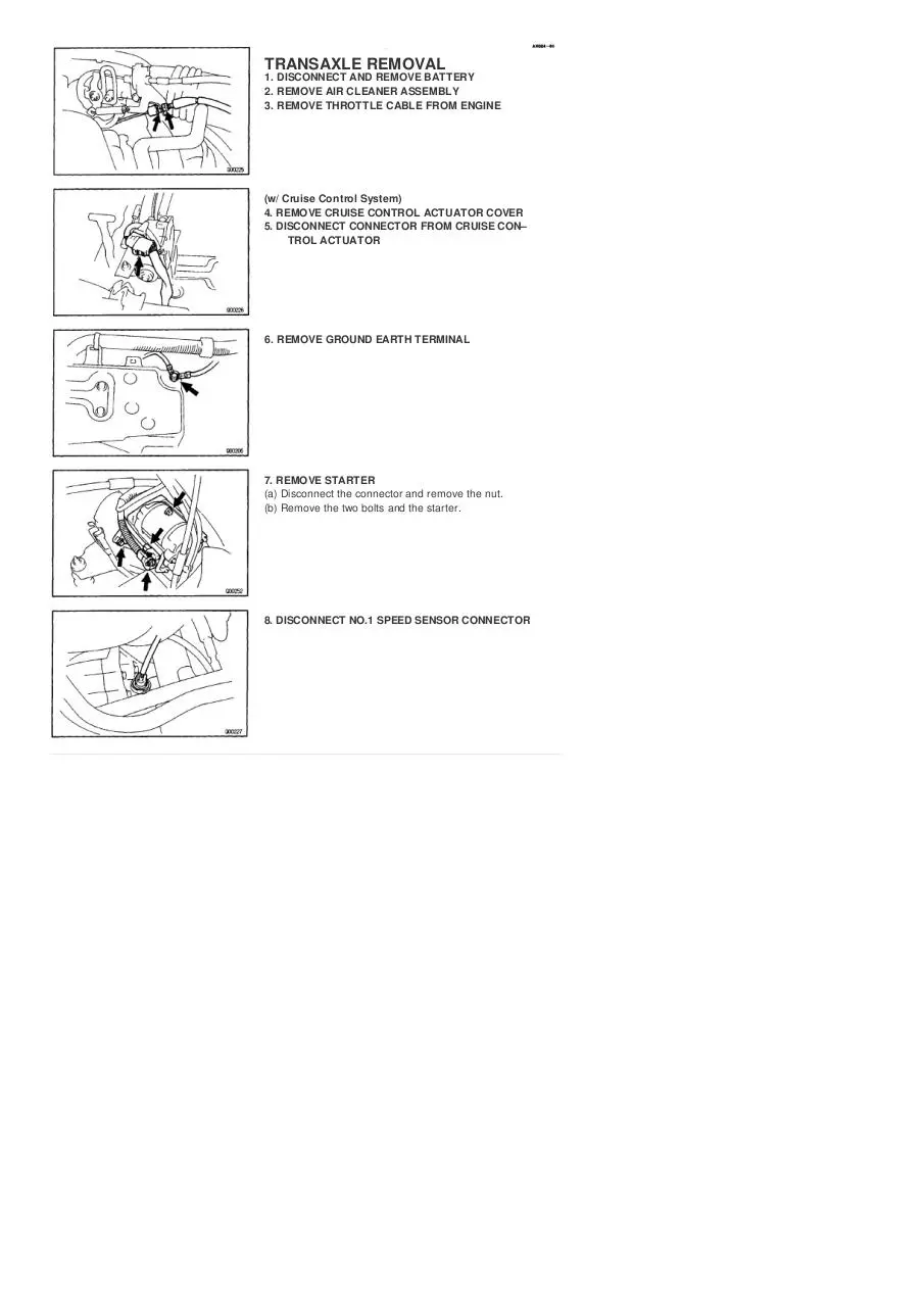
TRANSAXLE REMOVAL
1. DISCONNECT AND REMOVE BATTERY
2. REMOVE AIR CLEANER ASSEMBLY
3. REMOVE THROTTLE CABLE FROM ENGINE
(w/ Cruise Control System)
4. REMOVE CRUISE CONTROL ACTUATOR COVER
5. DISCONNECT CONNECTOR FROM CRUISE CON–
TROL ACTUATOR
6. REMOVE GROUND EARTH TERMINAL
7. REMOVE STARTER
(a) Disconnect the connector and remove the nut.
(b) Remove the two bolts and the starter.
8. DISCONNECT NO.1 SPEED SENSOR CONNECTOR
9. DISCONNECT NO.2 SPEED SENSOR CONNECTOR
10. DISCONNECT PARK/NEUTRAL POSITION SWITCH
CONNECTOR
11. DISCONNECT SOLENOID CONNECTOR
12. DISCONNECT SHIFT CONTROL CABLE
(a) Remove the clip from the shift control cable.
(b) Remove the unit.
13. DISCONNECT OIL COOLER HOSE
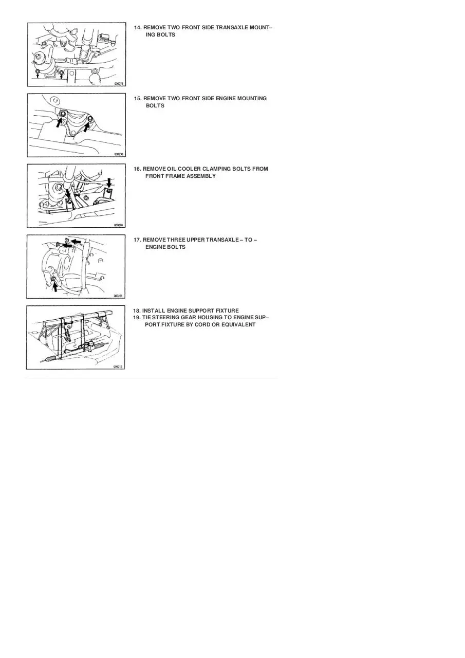
14. REMOVE TWO FRONT SIDE TRANSAXLE MOUNT–
ING BOLTS
15. REMOVE TWO FRONT SIDE ENGINE MOUNTING
BOLTS
16. REMOVE OIL COOLER CLAMPING BOLTS FROM
FRONT FRAME ASSEMBLY
17. REMOVE THREE UPPER TRANSAXLE – TO –
ENGINE BOLTS
18. INSTALL ENGINE SUPPORT FIXTURE
19. TIE STEERING GEAR HOUSING TO ENGINE SUP–
PORT FIXTURE BY CORD OR EQUIVALENT
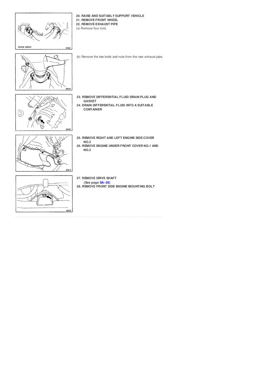
20. RAISE AND SUITABLY SUPPORT VEHICLE
21. REMOVE FRONT WHEEL
22. REMOVE EXHAUST PIPE
(a) Remove four nuts.
(b) Remove the two bolts and nuts from the rear exhaust pipe.
23. REMOVE DIFFERENTIAL FLUID DRAIN PLUG AND
GASKET
24. DRAIN DIFFERENTIAL FLUID INTO A SUITABLE
CONTAINER
25. REMOVE RIGHT AND LEFT ENGINE SIDE COVER
NO.2
26. REMOVE ENGINE UNDER FRONT COVER NO.1 AND
NO.2
27. REMOVE DRIVE SHAFT
(See page SA–20)
28. REMOVE FRONT SIDE ENGINE MOUNTING BOLT
29. REMOVE REAR SIDE ENGINE MOUNTING BOLTS
(a) Remove two hole plugs.
(b) Remove two bolts and nuts.
30. REMOVE FOUR LEFT SIDE TRANSAXLE MOUNT–
ING BOLTS
31. REMOVE STEERING GEAR HOUSING
(a) Remove the four bolts and disconnect the stabilizer
bar bush bracket from the front frame assembly.
(b) Remove two bolts and nuts from the steering gear housing.
(c) Remove the steering gear housing.
32. REMOVE FRONT FRAME ASSEMBLY
(a) Hold the front frame assembly with a jack.
(b) Remove two set screws from the right and left fender liners.
(c) Remove six bolts and four nuts.
(d) Remove the front frame assembly.
33. HOLD TRANSAXLE WITH A JACK
34. REMOVE REAR END PLATE
(a) Remove six bolts.
(b) Remove the rear end plate.
34. REMOVE TORQUE CONVERTER CLUTCH
MOUNTING BOLTS
(a) Turn the crankshaft to gain access to each bolt.
(b) Hold the crankshaft pulley nut with a wrench and remove
the six bolts.
36. REMOVE TRANSAXLE–TO–ENGINE BOLTS
37. REMOVE TRANSAXLE ASSEMBLY
Separate transaxle and engine, and lower the transaxle.
38. REMOVE TORQUE CONVERTER CLUTCH FROM
TRANSAXLE
TRANSAXLE INSTALLATION
1. INSTALL TORQUE CONVERTER CLUTCH IN
TRANSAXLE
if the torque converter clutch has been drained and
washed, refill with new ATF.
Fluid type:
ATF DEXTRON ® II
2. CHECK TORQUE CONVERTER CLUTCH
INSTALLATION
Using calipers and a straight edge, measure from the
installed surface to the front surface of the transmission
housing.
Correct distance:
More than 13.7 mm (0.539 in.)
3. ALIGN TRANSAXLE AT INSTALLATION POSITION
(a) Align the two knock pins on the block with the converter
housing.
(b) Temporarily install one bolt.
4. INSTALL TRANSAXLE–TO–ENGINE BOLTS
Install the transaxle–to–engine bolts.
12 mm head bolt
Torque: 64 N–m (650 kgf–cm, 47 ft–lbf)
10 mm head bolt
Torque: 46 N–m (470 kgf–cm, 34 ft–lbf)
5. INSTALL TORQUE CONVERTER CLUTCH
MOUNTING BOLTS
(a) Clean the threads of the bolts with the gasoline. ,
(b) Coat the threads of the bolts with sealer.
Sealer:Part No. 08833 – 00070, THREE BOND 1324 or equivalent
(c) Tighten the bolts evenly.
Torque: 27 N–m (280 kgf–cm, 20 ft–lbf)
HINT: First install dark green colored bolt and then the
five bolts.
6. INSTALL REAR END PLATE
(a) Install the rear and plate with the six bolts.
(b) Torque the six bolts.
Torque: 37 N–m (380 kgf–cm, 27 ft–lbf)
7. INSTALL FRONT FRAME ASSEMBLY
(a) Hold the front frame assembly with a jack.
(b) Install the six bolts and four nuts.
(c) Torque the bolts and nuts.
19 mm head bolt
Torque: 181 N–m (1,850 kgf–cm, 134 ft–lbf)
12 mm head bolt
Torque: 32 N–m (330 kgf–cm, 24 ft–lbf)
Nut
Torque: 36 N–m (370 kgf–cm, 27 ft–lbf)
Download 1993-transaxle-assembly-removal-camry
1993-transaxle-assembly-removal-camry.pdf (PDF, 1.62 MB)
Download PDF
Share this file on social networks
Link to this page
Permanent link
Use the permanent link to the download page to share your document on Facebook, Twitter, LinkedIn, or directly with a contact by e-Mail, Messenger, Whatsapp, Line..
Short link
Use the short link to share your document on Twitter or by text message (SMS)
HTML Code
Copy the following HTML code to share your document on a Website or Blog
QR Code to this page

This file has been shared publicly by a user of PDF Archive.
Document ID: 0000511256.