ELECTRIC BICYCLE INSTRUCTIONS.docx (PDF)
File information
Author: Courtney
This PDF 1.5 document has been generated by Microsoft® Word 2010, and has been sent on pdf-archive.com on 18/01/2017 at 15:38, from IP address 66.188.x.x.
The current document download page has been viewed 1260 times.
File size: 472.1 KB (8 pages).
Privacy: public file


File preview
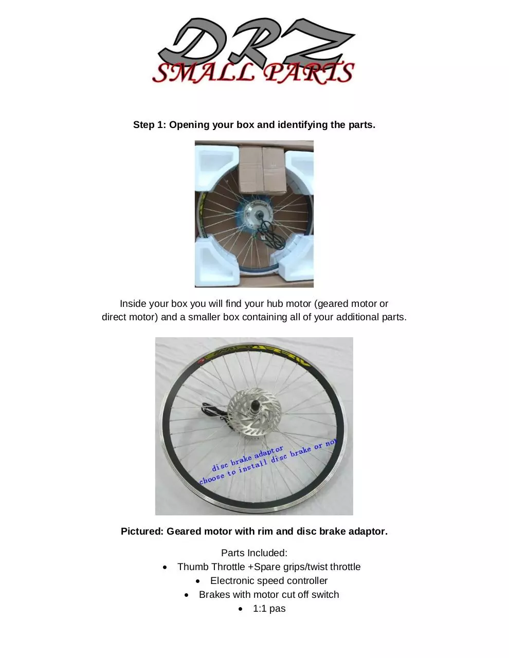
Step 1: Opening your box and identifying the parts.
Inside your box you will find your hub motor (geared motor or
direct motor) and a smaller box containing all of your additional parts.
Pictured: Geared motor with rim and disc brake adaptor.
Parts Included:
Thumb Throttle +Spare grips/twist throttle
Electronic speed controller
Brakes with motor cut off switch
1:1 pas
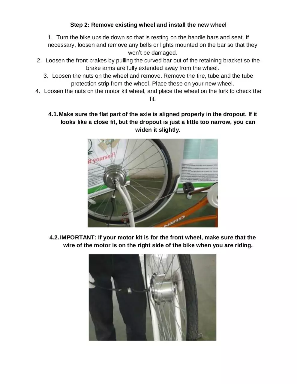
Step 2: Remove existing wheel and install the new wheel
1. Turn the bike upside down so that is resting on the handle bars and seat. If
necessary, loosen and remove any bells or lights mounted on the bar so that they
won’t be damaged.
2. Loosen the front brakes by pulling the curved bar out of the retaining bracket so the
brake arms are fully extended away from the wheel.
3. Loosen the nuts on the wheel and remove. Remove the tire, tube and the tube
protection strip from the wheel. Place these on your new wheel.
4. Loosen the nuts on the motor kit wheel, and place the wheel on the fork to check the
fit.
4.1. Make sure the flat part of the axle is aligned properly in the dropout. If it
looks like a close fit, but the dropout is just a little too narrow, you can
widen it slightly.
4.2. IMPORTANT: If your motor kit is for the front wheel, make sure that the
wire of the motor is on the right side of the bike when you are riding.
4.3. If you can see that the end of the axle is semi-open for wire, you will need
to make sure this semi-circular opening is in the right direction.
5. Make sure the axle is all the way into the dropouts and that the wheel is centered.
6. Verify that the washers are in the proper place, and torque down the axle nuts. Use
an 8 to 10 inch wrench. You will want to tighten these as tight as possible without
having to brace yourself or use leverage.
Step 3: Install 1:1 PAS
PAS Sensor and PAS Magnet
1. Use the tool shown in the image to remove your right pedal, and also the washer.
Put the PAS Sensor onto the end of the axle.
2. Insert the washer, and then put the PAS magnet on. Make sure the arrows on the
outside of the PAS magnet are going clockwise.
3. Install the pedal, and use the shown tool to tighten it as much as possible.
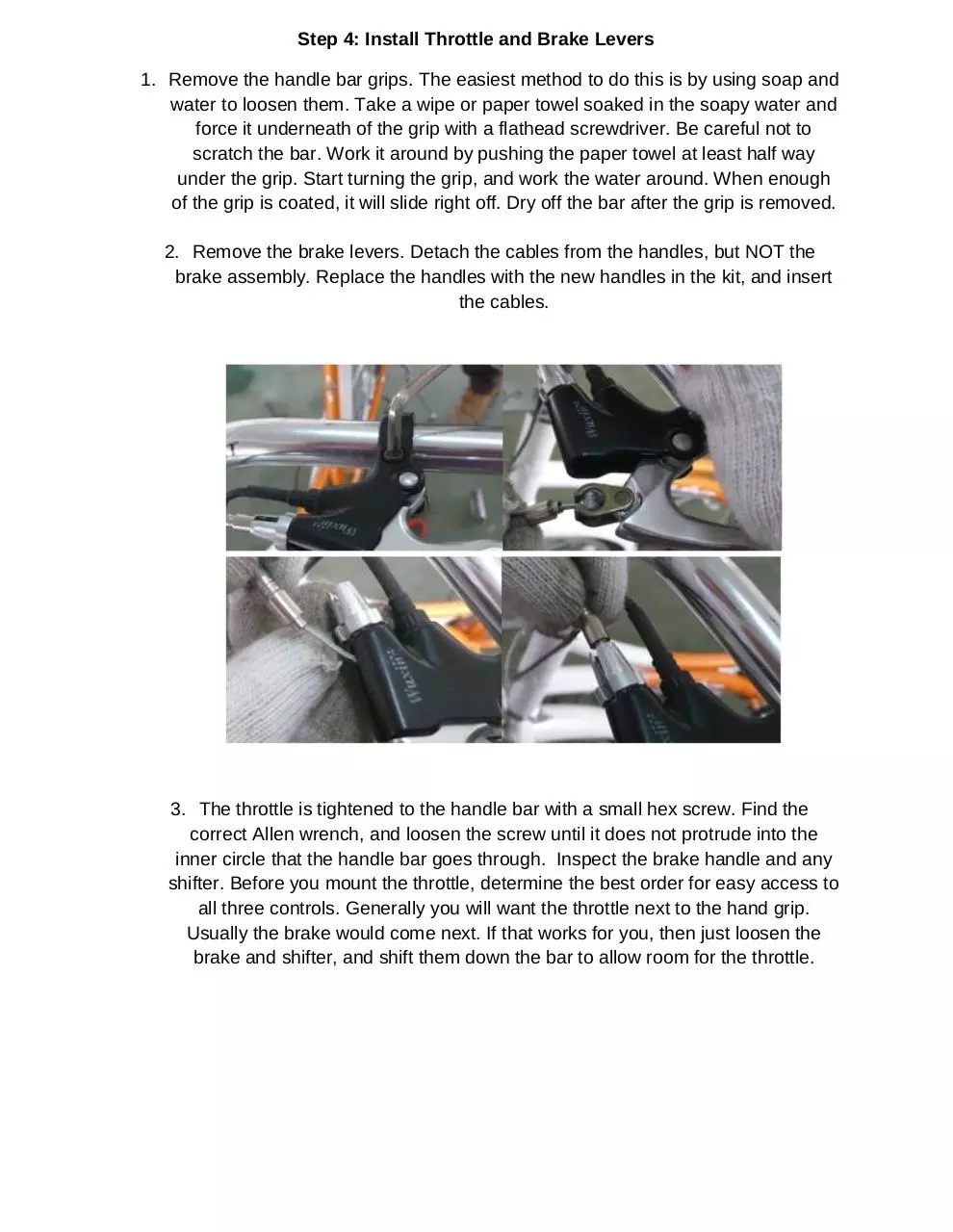
Step 4: Install Throttle and Brake Levers
1. Remove the handle bar grips. The easiest method to do this is by using soap and
water to loosen them. Take a wipe or paper towel soaked in the soapy water and
force it underneath of the grip with a flathead screwdriver. Be careful not to
scratch the bar. Work it around by pushing the paper towel at least half way
under the grip. Start turning the grip, and work the water around. When enough
of the grip is coated, it will slide right off. Dry off the bar after the grip is removed.
2. Remove the brake levers. Detach the cables from the handles, but NOT the
brake assembly. Replace the handles with the new handles in the kit, and insert
the cables.
3. The throttle is tightened to the handle bar with a small hex screw. Find the
correct Allen wrench, and loosen the screw until it does not protrude into the
inner circle that the handle bar goes through. Inspect the brake handle and any
shifter. Before you mount the throttle, determine the best order for easy access to
all three controls. Generally you will want the throttle next to the hand grip.
Usually the brake would come next. If that works for you, then just loosen the
brake and shifter, and shift them down the bar to allow room for the throttle.
4. Slide on the throttle. Be sure to allow enough room for the drop. Align this so that
the LEDs face up and toward the rider. Tighten the Allen screw. Slide the brake
lever and shifter back up the bar and tighten. Slide on the hand grip, making sure
to leave a small space between it and the throttle so that it doesn’t bind.
5. The width of the new rim may be different from the original, and the brakes may
need to be adjusted due to this. The curved tube holding the two brake pad
assemblies together so that they are extended out from the wheel has already be
detached. Using an Allen wrench loosen the brake pad. Hold the pad against the
rim and move it around until it is seated in the proper place. Repeat this on the
other side.
6. When both brakes are seated, insert the curved tube into the bracket. If there is
not enough slack, loosen the cable bolt and let out some cable until there is
about 1/8” of play before the brackets hit the rim. Re-tighten. Test the brakes to
make sure they are working properly.
Step 5: Run the wires with the protecting jacket and nylon ribbon
1. Run the wires from the throttle and brakes back to the controller. Use the
included tie-wraps to secure the cables to the frame.
2.
3. Run all of your cables towards the back of the bike and loosely zip tie them. Keep
them clean and as hidden as possible. Make sure that when running the cables
that you have a full turning radius without putting tension on the cables.
Step 6: Install the battery with the frame, box, and bag. (NOT INCLUDED)
1. Mount the front of the rack to both post bolts on the seat, and mount to each side
of the back axle. Make sure this is fitted, and tighten all bolts.
2. Put the battery into the rack and connect the controller box with the battery. Put
the cables into this box to prepare to connect them to the controller.
Step 7: Connect the controller
NOTE: The limited speed wire can limit the speed to 12mp/h (20km/h). You may choose
to keep this disconnected.
NOTE: The red wire (with no label on the diagram) does not need to be connected
Download ELECTRIC BICYCLE INSTRUCTIONS.docx
ELECTRIC BICYCLE INSTRUCTIONS.docx.pdf (PDF, 472.1 KB)
Download PDF
Share this file on social networks
Link to this page
Permanent link
Use the permanent link to the download page to share your document on Facebook, Twitter, LinkedIn, or directly with a contact by e-Mail, Messenger, Whatsapp, Line..
Short link
Use the short link to share your document on Twitter or by text message (SMS)
HTML Code
Copy the following HTML code to share your document on a Website or Blog
QR Code to this page

This file has been shared publicly by a user of PDF Archive.
Document ID: 0000538561.