U.M. Mara 15B Stove 6 button LED (PDF)
File information
This PDF 1.4 document has been generated by , and has been sent on pdf-archive.com on 17/03/2017 at 10:40, from IP address 195.113.x.x.
The current document download page has been viewed 540 times.
File size: 2.48 MB (28 pages).
Privacy: public file


File preview
Thermostove 15
Cod. 001143
We thank you for having chosen one of our products, the fruit of technological experience and of continual research for
a superior quality product in terms of safety, dependability, and service.
In this manual you will find all the information and useful suggestions to use your product with the maximum safety
and efficiency.
Please remember that the first power must be carried out by our Authorized Assistance
Center (Law 37/2008), which verifies the installation and completes the warranty.
Any kind of tampering or unauthorized substitution with non-original spare parts can be
dangerous to the safety of the operator and relieves the manufacturer from any civil or
criminal liability.
• Incorrect installation, incorrectly performed maintenance, improper use of the product release the manufacturer from
every eventual damage derived from the use of the stove.
• The unit cannot be used as an incinerator. Do not use fuels other than pellets.
• This manual has been realized by the manufacturer and constitutes an integral part of the product and must remain
with it during its entire lifetime. If the product is sold or transferred, be sure that the booklet is present since the
information contained in it are addressed to the buyer, and to all those persons of various titles who complete the
installation, use and maintenance.
• Carefully read the instructions and the technical information contained in this manual, before proceeding with the
installation, use, and any operation on the product.
• The observance of the indications contained in the present manual guarantees the safety of people and the product,
the economy of use and a longer functioning lifetime.
• Although the carefully studied design and the risk analysis done by our company has permitted the realization of a
safe product, in any case, before effecting any operation on the stove, it is recommended to keep said manual available and pay scrupulous attention to the instructions written therein.
• Be very careful when moving the ceramic details where present.
• Check the precise flatness of the pavement where the product will be installed
• The wall where the product will be placed must not be constructed in wood, or in any case, made of an inflammable
material, and in addition it is necessary to maintain a safety distance.
• While the stove is in operation, several parts of the stove (door, handle, sides) can reach high temperatures. Therefore
pay attention and use the proper precautions, above all in the presence of children, elderly or disabled persons, and
animals.
• Assembly must be performed by authorized persons (Authorized Assistance Center).
• Diagrams and drawings are furnished for the purpose of illustration; the manufacturer, with the intent of pursuing a
policy of constant development and renewal of the product can, without any notice, make any modifications that are
believed opportune.
• When the stove is working at its maximum speed, it is strongly suggested to wear gloves while handling with the
door for pellets loading and the door handle.
• It is prohibited to install in bedrooms or in explosive environments.
• Only use replacement parts recommended by the supplier.
Never cover the body of the stove in any way or obstruct the openings placed on the upper side
when the device is operating. All our stoves are trial lighted on the construction line.
In the event of a fire, disconnect the power supply, use an extinguisher and call the fire fighters if necessary.
After that contact the Authorized Assistance Center.
This instruction booklet is an integral part of the product: make sure that it always accompanies the appliance, even in
case of transfer to another owner or in the case of transfer to another place. In the event of damage or loss, request a
copy from the area technician.
These symbols indicate specific messages in this booklet:
ATTENTION:
This warning sign indicates that the message to which it refers should be carefully read and understood,
because failure to comply with what these notices say can cause serious damage to the stove and
put the user’s safety at risk.
INFORMATION:
This symbol is used to highlight information which is important for proper stove operation. Failure to
comply with these provision will compromise use of the stove and its operation will not be satisfactory.
29
GB
Dear Customer,
GB
Norms and declarations of conformity
Our company declares that the stove conforms to the following norms for the EC European Directive labelling:
• 2004 /108 CE (regulation EMC) and following
amendments;
• 2006/95 CE (low tension regulation) and following
amendments;
• 2011/65 EU (RoHS 2 directive);
• The New Rules of Construction Products (CPR-Construction Products Regulation) No. 305/2011 regarding
the construction world;
• For installations in Italy, please refer to UNI 10683/98 or
following changes. For the water-thermo-sanitary equipment, let the installer give you the conformity declaration
in compliance with L. 37/2008. While installing the unit
respect the local, national and Europen rules;
• EN 55014-1; EN 55014-2; EN 61000-3-2; EN 61000-3-3;
EN 60335-1; EN 60335-2-102; EN 62233, EN 50581.
Safety information
Please carefully read this use and maintenance manual
before installing and operating the stove!
If clarification is needed, please contact the dealer or the
Authorized Assistance Center.
• The pellet stove must only be operated in living environments. This stove, being controlled by an electronic
board, permits a completely automatic and controlled
combustion; the exchange, in fact, regulates the lighting
phase, 5 power levels and the shut down stage, guaranteeing the safe operation of the stove.
• The basket used for combustion allows most of the ash
produced by the combustion of the pellets to fall into
the collection compartment. Nevertheless, check the
basket daily, given that not all pellets have high quality
standards (use only quality pellets recommended by the
manufacturer).
Responsibility
With the delivery of the present manual, we decline all
responsibility, both civil and penal, for accidents deriving
from the partial or total lack of observance of the instructions contained herein.
We decline every responsibility derived from improper
use of the stove, from incorrect use by the user, from unauthorized modifications and/or repairs, from the use of
replacement parts that are not original for this model.
The manufacturer declines every civil or penal, direct or
indirect responsibility due to:
• Lack of maintenance;
• Failure to observe the instructions contained in the
manual;
• Use in non-conformity with the safety directives;
30
• Installation in non-conformity with the norms in force in
the country;
• Installation by unqualified or untrained personnel;
• Modifications and repairs not authorized by the manufacturer;
• Use of non-original replacement parts;
• Exceptional events.
• Use only wood pellets;
• Keep / store the pellets in a cool dry
place;
• Never pour pellets directly on the hearth;
• The thermostove must only be fed with quality
6 mm diameter pellets of the type recommended by the manufacturer;
• Before making the electrical connection of the
thermostove the discharge tubes must be connected with the flue;
• The protective grill placed inside the pellet container must never be removed;
• The environment where the stove is installed
must have a sufficient exchange of air;
• It is forbidden to operate the thermostove with
the door open or the glass broken;
• Do not use the thermostove as an incinerator;
the thermostove should be used only for the intended purpose;
• Any other use is considered improper and therefore dangerous. Do not put in the hopper other
than wood pellets;
• When the thermostove is operating, the surfaces, glass, handle and tubes become very hot:
during operation do not touch these parts without adequate protection;
• Keep the fuel and other inflammable materials
off the thermostove.
Fuel is loaded from the upper part of the stove by opening
a door.
Pour the pellets in the hopper; vacuum contains about 17
kg of pellets.
This is easier if performed in two steps:
• Pour half of the contents of the bag into the hopper and
wait for the fuel to settle on the bottom.
• Then pour in the second half;
• Keep the cover closed , after loading the pellets , the lid
of the fuel tank;
GB
Charge pellet
Never remove the protection grille in the
hopper. When filling, do not let the sack
of pellets touch any hot surfaces.
The thermostove is a product by heating, presents the external surfaces particularly hot. For this reason, we recommend extreme caution when operating in particular:
• Do not touch the stove body and the various components, do not approach the door , it could cause burns;
• Do not touch the exhaust fumes;
• Do not perform any type of cleaning;
• Do not dump the ashes;
• Do not open the ash tray;
• Be careful that children do not come near;
Instructions for safe and efficient use
• The appliance is not intended for use by persons ( including children) with reduced physical, sensory or mental capacities , or lack of experience or knowledge, unless
they have been given through the intermediary of a person responsible for their safety, supervision or instruction
concerning use of the appliance;
• The thermostove must be connected to an electrical
system equipped with an earthing conductor in accordance with regulations 73/23 and 93/98 EEC;
• Do not use the thermostove as a ladder or scaffold;
• Do not wash the inside of the thermostove with water.
The water could damage the electrical insulation, causing
electric shock;
• Do not put clothes to dry on the thermostove.
Any clothes hangers and suchlike must be kept a suitable
distance from the stove. - Risk of fire
• Carefully explain that the thermostove is made from material subjected to high temperatures for the elderly , the
disabled, and in particular for all children, keeping them
away from the thermostove during operation
• Do not touch the thermostove with wet hands: the thermostove has electrical components that could produce
sparks if handled incorrectly.
• Never open the glass door of the pellet stove while the
thermostove is in operation.
• The system must be of adequate electrical power declared the thermostove;
• Do not expose your body to hot air for a long time. Do
not overheat the room you are in and where the thermostove is installed.
This can damage the physical conditions and cause
health problems;
• Do not expose to direct the flow of hot air plants or
animals;
• The pellet thermostove is not a cooking element;
• External surfaces during operation can become very
hot. Do not touch them except with the appropriate protection.
31
GB
Operating area
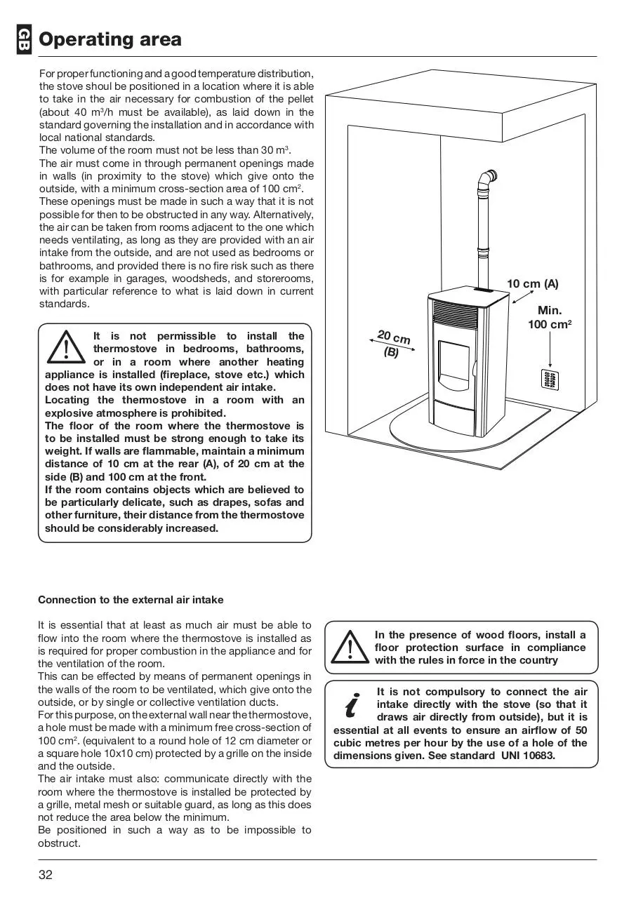
For proper functioning and a good temperature distribution,
the stove shoul be positioned in a location where it is able
to take in the air necessary for combustion of the pellet
(about 40 m3/h must be available), as laid down in the
standard governing the installation and in accordance with
local national standards.
The volume of the room must not be less than 30 m3.
The air must come in through permanent openings made
in walls (in proximity to the stove) which give onto the
outside, with a minimum cross-section area of 100 cm2.
These openings must be made in such a way that it is not
possible for then to be obstructed in any way. Alternatively,
the air can be taken from rooms adjacent to the one which
needs ventilating, as long as they are provided with an air
intake from the outside, and are not used as bedrooms or
bathrooms, and provided there is no fire risk such as there
is for example in garages, woodsheds, and storerooms,
with particular reference to what is laid down in current
standards.
It is not permissible to install the
thermostove in bedrooms, bathrooms,
or in a room where another heating
appliance is installed (fireplace, stove etc.) which
does not have its own independent air intake.
Locating the thermostove in a room with an
explosive atmosphere is prohibited.
The floor of the room where the thermostove is
to be installed must be strong enough to take its
weight. If walls are flammable, maintain a minimum
distance of 10 cm at the rear (A), of 20 cm at the
side (B) and 100 cm at the front.
If the room contains objects which are believed to
be particularly delicate, such as drapes, sofas and
other furniture, their distance from the thermostove
should be considerably increased.
10 cm (A)
20 cm
(B)
Min.
100 cm2
Connection to the external air intake
It is essential that at least as much air must be able to
flow into the room where the thermostove is installed as
is required for proper combustion in the appliance and for
the ventilation of the room.
This can be effected by means of permanent openings in
the walls of the room to be ventilated, which give onto the
outside, or by single or collective ventilation ducts.
For this purpose, on the external wall near the thermostove,
a hole must be made with a minimum free cross-section of
100 cm2. (equivalent to a round hole of 12 cm diameter or
a square hole 10x10 cm) protected by a grille on the inside
and the outside.
The air intake must also: communicate directly with the
room where the thermostove is installed be protected by
a grille, metal mesh or suitable guard, as long as this does
not reduce the area below the minimum.
Be positioned in such a way as to be impossible to
obstruct.
32
In the presence of wood floors, install a
floor protection surface in compliance
with the rules in force in the country
It is not compulsory to connect the air
intake directly with the stove (so that it
draws air directly from outside), but it is
essential at all events to ensure an airflow of 50
cubic metres per hour by the use of a hole of the
dimensions given. See standard UNI 10683.
GB
Connection to the flue pipe
The flue pipe must have internal dimensions not larger
than 20x20 cm, or diameter 20 cm. In the event of larger
dimensions, or of the flue pipe being in poor condition ( for
example cracks, poor insulation, etc.), it is advisable to fit
a stainless steel pipe of suitable diameter inside the flue
pipe throughout its length, right up to the top.
Check with suitable instruments that there is a draught
between 10 Pa and 12 Pa. This type of connection
ensures the evacuation of the fumes even in the event of
a temporary power cut.
At the bottom of the flue pipe, provide an inspection cap
to allow periodic checking and cleaning, which must be
done annually. Make a gas-tight connection to the flue
pipe, using pipes and connectors as recommended by us.
You must ensure that a windproof cowl should be fitted
which complies with the standards in force
Connection to an external flue with insulated or
double-wall pipe
The only type of pipe which is permissible is insulated
(double-walled) stainless steel, smooth on the inside,
fixed to the wall. Flexible stainless steel pipe must not be
used. At the bottom of the flue pipe, provide an inspection
cap to allow periodic checking and cleaning, which must
be done annually. Make a gas-tight connection to the flue
pipe, using pipes and connectors as recommended by us.
You must ensure that a windproof cowl should be fitted
which complies with the standards in force.
Check with suitable instruments that there is a draught
between 10 Pa and 12 Pa.
Connection to the flue pipe
For proper functioning, the connecting pipe between the
stove and the chimney or flue duct must have a slope of
not less than 3% in the horizontal stretches, the length of
which must not exceed 2 metres and the vertical distance
between one tee connector and another (change of
direction) must not be less than 1,5 m.
Check with suitable instruments that there is a draught
between 10 Pa and 12 Pa. At the botton of the flue pipe,
provide an inspection cap to allow periodic checking and
cleaning, which must be done annually.
Make a gas-tight connection to the flue pipe, using pipes
and connectors as recommended by us. You must ensure
that a windproof cowl should be fitted which complies
with the standards in force.
Fig. 2: connection to the
flue pipe.
Fig. 3: connection to an
external flue with insulated
or double-wall pipe.
33
GB
Fireplace flue gas
Distance to objects
Avoid contact with combustible materials (example:
wooden beams) and in any case provide for their insulation
with flame retardant material. In case of pipe penetrations
through roofs or walls is recommended to use special
kits crossing, certificates, are available commercially. In
the event of a chimney fire, turn off the stove, disconnect
from the network and never open the door. Then call the
authorities.
It is also recommended to keep the pellets and all
flammable materials at a suitable distance from the
termostove.
10 cm
20 cm
The chimney cap
The chimney cap must respect the following requirements:
• It must have the equivalent diameter and internal form
of the flue.
• It must have a useful outlet diameter of not less than
double that of the flue.
• The chimney cap on the roof or that remains in contact
with the outside (for example, in case of open lofts or attics), must be covered with elements in brick or tile and
must, in any case, be well insulated.
• It must be constructed to prevent rain, snow, and extraneous bodies from entering the flue and so that the
discharge of the products of combustion is not inhibited
by wind from any quarter or strength (wind-proof chimney cap).
• The chimney cap must be positioned in such a way as
to guarantee the adequate dispersion and dilution of the
products of combustion and in any case, must be out of
the reflux zone. This zone has different dimensions and
forms according to the angle of inclination of the roof so
it is necessary to adopt minimum heights (Fig. 2).
• The chimney cap must be a wind-proof type and must
be above the ridge.
• Eventual structures or other obstacles that are higher
than the chimney cap must not be too close to the
chimney cap itself.
• The device should not be installed in the flue shared.
YES
NO
Fig. 5: Characteristics of chimney
34
150 cm
REMARKS:
- the appliance must be installed by a qualified technician in
possession of the technical and professional requirements
according to the DM37/2008 that, under its responsibility,
to ensure compliance with the rules of good technique.
- the thermostove must be connected to a heating system
and/or to a network of production of sanitary hot water,
consistent with its performance and its power
- you need to keep in mind all laws and national, regional,
provincial and municipal laws of the country in which you
installed the device
- check that the floor is not flammable: if necessary use a
suitable platform
- in the room where the generator must be installed to
heat must not pre-exist or be installed with an extractor
hood or ventilation ducts of the collective type.
Should these devices be located in adjacent rooms
communicating with the installation, and ‘prohibited the
simultaneous use of the heat generator, where there is a
risk that one of the two rooms being placed in depression
than the other
- it is not permissible to install in bedrooms or bathrooms
- for hydraulic connections (see next chapter) it is advisable
to use where possible of hoses
GB
Remote Control
The remote control (Fig. 3) used to adjust water temperature
power and the on/off functions for the pellet thermostove.
Replace the battery observing the correct polarity (Fig. 4)
Size:
12V
Size: 12V
To start the thermostove, press keys
and
simultaneously. The thermostove will automatically enter
the starting phase.
Press keys
and
to adjust water temperature, and
use keys
e
to adjust operating power.
To turn off the thermostove, hold down keys
and
simultaneously.
To replace the 12 volt battery located on the back of the
remote control; use a screwdrives as a lever to lift the
cover.
Fig. 3
Fig. 4
Technical Specification
N.B.: measures with a tolerance of about 10 mm
35
GB
PARAMETER
M. UNITS
NSAT150
Heat input
kW
14,79
Nominal heat output
kW
13,84
Reduced heat output
kW
5,04
Water heat output
kW
10,53
Reduced water heat output
kW
3,81
CO concentration at nominal reference (13% O2)
mg/m3
230,7
CO concentration at reduced reference (13% O2)
mg/m3
299,2
Nominal efficiency
%
93,54
Reduced efficiency
%
96,29
Pellet consumption (min-max)
Kg/h
1,067 - 3,017
Heated surface
mc
270
Flue gas flow rate (min-max)
g/s
4,3 - 8,5
Draft (min-max)
Pa
10 - 12
Flue gas temperature (min-max)
°C
63 - 124,8
Boiler water
litri
17
Maximum working pressure
Bar
1,5
Tank capacity
Kg
17
Smoke outlet tube
mm
80
Diameter air intake
mm
50
Connecting health
Inch
3/4
Nominal voltage
V
230
Nominal frequency
Hz
50
Power consumption max
W
350
Thermostove weight
Kg
130
N° Test Report
36
K 11952013T1
Remove any components wich might
burn from the firebox and from the glass
(various instructions and adhesive labels)
GB
Thermostove start up
2
1
3
4
6
Charge pellet
Fig. 2
Fuel is loaded from the upper part of the thermostove
by opening a door. Pour the pellets in the hopper. When
empty, it will hold slightly more than a 15 kg sack.
This is easier if performed in two steps:
• Pour half of the contents of the bag into the hopper and
wait for the fuel to settle on the bottom.
• Then pour in the rest.
Never remove the protection grille in the
hopper. When filling, do not let the sack of
pellets touch any hot surfaces.
The brazier should be cleaned before each
starting.
Control Panel (Fig. 2)
Button is used to switch on and / or off the thermostove
and to exit programming.
Buttons
and
are used to adjust temperature, for
displays and for the programming functions.
Buttons
and
are used to adjust heating power.
Button
is used to adjust temperature and programming
functions.
The upper and lower displays are used to view different
messages.
Led
Symbol
Description
1
The LED is on when the parameter
UT01 on the menu is not on OFF and
the weekly or daily programming are
set.
2
The LED starts up every time the stove
is loading pellets
3
The LED blinks when the board
signalises a change in temperature
or power set by the infrared remote
control.
4
The LED is on when the room
temperature reaches the value set on
the menu SET Water.
5
The LED blinks to indicate that you are
entering the menu user/technician or
that you are modifying the temperature
set.
6
“SET“
5
The LED switches on when the water
circulator is working.
It is advisable to use dry wood pellets, up
to 6 mm in diameter.
Preliminary checks
Before switching on the pellet stove, make sure that the
pellet hopper is full, the combustion chamber is clean, the
glass door is closed, the power supply plug is connected
and the switch on the back is set to “1.”
Starting the thermostove
Press button for a couple of seconds until the thermostove starts.
“FAN” will be displayed on the
upper display and “ACC” on the
lower one. During this phase the
unit will carry out a diagnosis
(around 20 seconds) on the fume
extraction system.
“LOAD WOOD ”, is the next phase,
which indicates pellets should
be fed. The glow plug will heat
up to light the fire.
When the fume temperature is
50º C (approx. 10 minutes), the
thermostove will confirm the
ignition: “FIRE” will be shown on
the upper display and “ON” on
the lower one.
After this phase, which lasts
around 5 minutes, the heating
power (es. “p06”) and the room
temperature (es. “25C”), will be
simultaneously shown on the
upper display, and the system
delivery water temperature will
be shown on the lower display.
If the flame does not start up correctly within 10 minutes,
the thermostove jams: you will read the words “ALAR” on
the upper display and the words “NO ACC ”: blinking on the
lower display.
Wait 10 minutes until the cooling phase is completed,
open the door, empty the brazier and start a new light-up.
37
Download U.M. Mara 15B Stove 6 button LED
U.M. Mara 15B Stove 6 button LED.pdf (PDF, 2.48 MB)
Download PDF
Share this file on social networks
Link to this page
Permanent link
Use the permanent link to the download page to share your document on Facebook, Twitter, LinkedIn, or directly with a contact by e-Mail, Messenger, Whatsapp, Line..
Short link
Use the short link to share your document on Twitter or by text message (SMS)
HTML Code
Copy the following HTML code to share your document on a Website or Blog
QR Code to this page

This file has been shared publicly by a user of PDF Archive.
Document ID: 0000570367.