HT60 installation guide (PDF)
File information
Title: Microsoft Word - HT60 installation guide v2.0.docx
Author: sleasure
This PDF 1.5 document has been generated by PScript5.dll Version 5.2.2 / Acrobat Distiller 11.0 (Windows), and has been sent on pdf-archive.com on 12/04/2017 at 13:30, from IP address 141.123.x.x.
The current document download page has been viewed 446 times.
File size: 181.78 KB (8 pages).
Privacy: public file


File preview
HT60 Installation Guide
Thank you for your purchase of the HT60 system.
If we can be of assistance in any way please contact us at
http://huntingtactical.com/contact‐us/
In addition to this instruction guide a video of the installation steps
may be found on our website at
http://huntingtactical.com/HT60
1. Tools: Depending on which generation of rifle you have, the tools may vary a little.
The included 5/16 Allen wrench
Flat head screw driver
AR multi‐tool (you can also use a spanner wrench or a pair of slip jaw pliers
Small knife (to open the packaging)
Slip jaw pliers
Note: It is important to use a pair of pliers that are not going to scratch or mar the surface of your
stock.
2. Unboxing the HT60 stock: Using a small knife I’ll cut the security sticker on one end. Slide the
outer package off and take a look at what we have.
a. Package Contents:
Package of hardware that has two (2) short screws, three (3) long screws, seven (7)
hex‐head nuts, one (1) flat washer (that is only used when installing the stock on the
model 795)
5/16 Allen wrench
Locking pin (and the small roll pin)
Lock ring
Castle nut
Lock lever
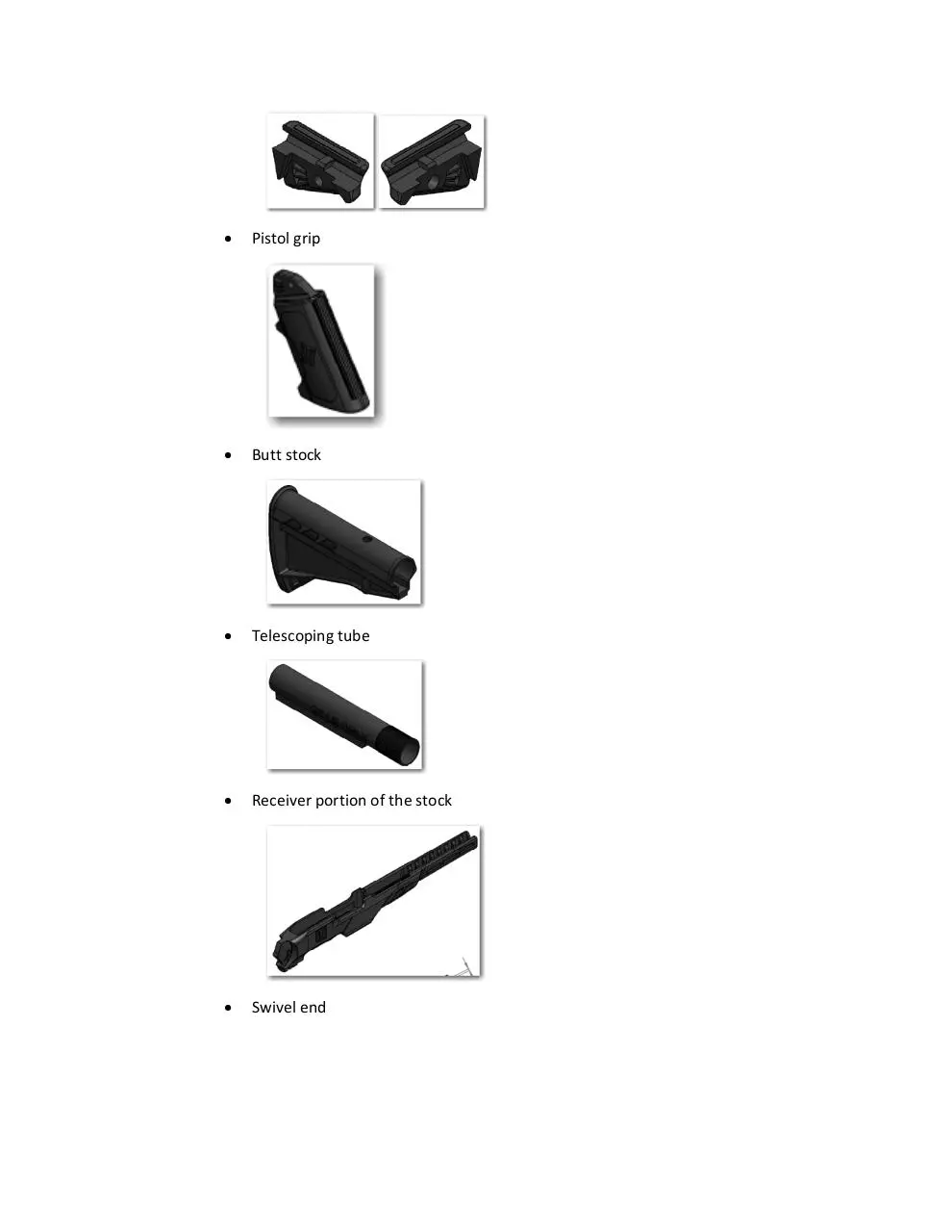
Pistol grip mount (make sure you have a left and a right side)
Pistol grip
Butt stock
Telescoping tube
Receiver portion of the stock
Swivel end
Magazine port plug
Adjustable Picatinny Rail Forearm
Stock Assembly
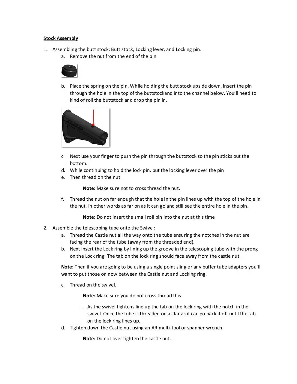
1. Assembling the butt stock: Butt stock, Locking lever, and Locking pin.
a. Remove the nut from the end of the pin
b. Place the spring on the pin. While holding the butt stock upside down, insert the pin
through the hole in the top of the buttstockand into the channel below. You’ll need to
kind of roll the buttstock and drop the pin in.
c. Next use your finger to push the pin through the buttstock so the pin sticks out the
bottom.
d. While continuing to hold the lock pin, put the locking lever over the pin
e. Then thread on the nut.
Note: Make sure not to cross thread the nut.
f.
Thread the nut on far enough that the hole in the pin lines up with the top of the hole in
the nut. In other words as far on as it can go and still see the entire hole in the pin.
Note: Do not insert the small roll pin into the nut at this time
2. Assemble the telescoping tube onto the Swivel:
a. Thread the Castle nut all the way onto the tube ensuring the notches in the nut are
facing the rear of the tube (away from the threaded end).
b. Next insert the Lock ring by lining up the groove in the telescoping tube with the prong
on the Lock ring. The tab on the lock ring should face away from the castle nut.
Note: Then if you are going to be using a single point sling or any buffer tube adapters you’ll
want to put those on now between the Castle nut and Locking ring.
c. Thread on the swivel.
Note: Make sure you do not cross thread this.
i. As the swivel tightens line up the tab on the lock ring with the notch in the
swivel. Once the tube is threaded on as far as it can go back it off until the tab
on the lock ring lines up.
d. Tighten down the Castle nut using an AR multi‐tool or spanner wrench.
Note: Do not over tighten the castle nut.
Note: If you’re going to use a pair of slip jaw pliers take care to avoid scratching
the surface of the castle nut.
3. Swivel Assembly: 5/16 Allen wrench
a. Insert three (3) nuts into hex‐shaped pockets at the swivel end (rear) of the receiver.
i. There are two (2) on one side and one (1) on the other.
Note: Ensure that these lay flush and straight into the receiver. You may need to
press firmly with a pair of slip jaw pliers.
Note: You can also place a small amount of superglue on the edges of the nuts to
hold them in place. This is not required however may be handy if you are going to
be adjusting the stock frequently.
b. Next put the swivel on by sliding the slotted end over the receiver.
i. Ensure that the holes in the Receiver and Swivel are properly aligned.
c. Putting another nut into the left side of the swivel and a long screw into the right side;
tighten down the swivel hand tight but allow for some movement.
Note: Ensure the hole in the Receiver and Swivel are properly aligned. Failure to
do so may result in cross‐threading the nut. The screw should go in very easily and
evenly. If you notice one side of the nut is pushing out as you attempt to thread it
in then most likely the holes are not properly aligned.
Note: To make this easier you may want to insert a screwdriver or something into
the nut side to stop the nut from pushing out.
d. Then using another long screw as a set screw lock the swivel in place.
Note: You can choose any of the three (3) positions here. You can always adjust
this later as well if you need to. This feature is one of the nicest parts of the HT60
stock. Depending on whether you’re going to be using a scope, red dot or barrel
sights, and your body size, you can adjust the angle to provide the best sight
picture.
e. Tighten both screws down with the 5/16 Allen wrench.
Note: It’s important not to over‐tighten these screws. Just make them nice and
snug. If you had a torque wrench, 30 inch pounds would be more than enough.
4. Buttstock on the telescoping tube:
a. Grabbing each side of the locking lever between your fingers at the point of the locking
pin; pull out on the locking lever. Pulling the entire locking lever away from the butt
stock, fully compressing the spring, so that the pin is not visible inside of the butt stock.
b. Slide the butt stock over the end of the telescoping tube.
Note: Then by depressing the locking lever you can move it to any of the six
positions. It helps if you hold the stock receiver between your knees.
c. Adjust the locking pin:
i. Tighten or loosen the locking pin until you are no longer able to change
positions by depressing the locking lever.
ii. Tighten the locking pin in half‐turn increments (so that the hole in the nut and
pin lineup) until you are able to change positions by depressing the locking
lever.
CAUTION! Over adjustment may result in the locking pin not fully seating in the
telescoping tube causing the tube to fail; possibly resulting in injury and damage.
iii. Insert the roll pin to hold the nut in place using slip jaw pliers:
1. Insert the roll pin into the hole in the nut/lock pin.
2. Using the slip jaw pliers push the pin in as far as it will go.
Note: This is probably the most difficult part of the assembly. The pin should not
come out with your fingers.
5. Assemble the Adjustable Picatinny Rail Forearm:
a. Insert three (3) nuts into the hex‐shaped holes inside of the stock near the front.
Note: You should still do this even if you do not intend on installing the Adjustable
Picatinny Rail forearm. That way it can be added on later without removing the
rifle from the stock.
b. Holding the stock top‐side up, slide the Adjustable Picatinny Rail Forearm into place,
with the angled end facing the rear of the stock.
Note: There are three (3) holes in the receiver and only two (2) in the forearm. You will line
it up to where it is comfortable for you. Again, you can always adjust this later. This allows
you to fine tune the stock for balance and fit when you’re using any Picatinny Rail mounted
accessories like a fore‐grip, or flashlight.
c. Thread‐in the two (2) short screws and tighten them down using the 5/16 Allen wrench.
Note: Do not over tighten these screws. Just enough to lock the forearm in place.
Note: You can also place a small amount of superglue on the edges of the nuts to
hold them in place. This is not required however may be handy if you are going to
be removing the forearm frequently.
6. Installing the HT60 stock onto your firearm:
Model 60
a. Install the magazine port plug.
i. The rear of the magazine port plug slides up inside and the front fits in on the
bottom of the stock.
Note: You’ll skip this step if you’re installing the stock on a model 70 or 795.
b. For both the model 60 and 70 you’ll insert the flat washer you removed, when taking
the trigger out of the factory stock, and hold it in place with your finger.
c. Insert the trigger assembly in place and tighten down the small front screw using a flat
head screwdriver. With the model 70 you’ll also want to install the magazine port
shroud before tightening down the screw.
WARNING: When inserting the trigger assembly ensure the assembly is level and
fully seated before tightening. Failure to do so may result in damage to the trigger
assembly. DO NOT use the takedown screws to draw the trigger assembly into
place. This may result in damage to the assembly and/or firearm receiver.
Model 795
a. Insert the small washer in the front hole between the trigger assembly and the stock.
WARNING: If you do not install this washer you will crack your trigger assembly
when tightening down assembly to the rifle.
b. Next insert the trigger assembly in place and hold it with your hand while you perform
the next step.
All Models
a. Insert the rifle into the stock, ensuring the holes in the receiver are properly lined up
with the holes in the stock and trigger assembly.
b. Insert the Front and Rear Takedown screws.
Note: Before you tighten down the screws ensure the rifle and trigger assembly
are fully seated into the stock. The trigger assembly screws should start and
tighten easily. If they are difficult to start or tighten check alignment to ensure
they are not cross threading.
Note: Be sure not to over tighten them.
Note: For the model 795 you’ll need to tip the rifle slightly on its side and jiggle it
to get the bolt release lever through the slot in the trigger housing.
Note: Customers have reported the best practice for this is to have stock upside‐
down, place the washer in position in the stock, roll the trigger guard over the bolt
release lever.
7. Pistol Grip Installation:
a. Laying the rifle on its left side place the left side mount in place (the side with the
threaded insert).
b. Line up the tab in the mount with the grove in the mounting rail.
Note: Here you can determine how close to the trigger you want the grip. There
are three (3) points of adjustment. You can always move this later if you find it is
not adjusted properly for you.
c. Line up the grip with the hole in the mount.
Note: Notice the teeth on the grip matchup with the groves in the mount. This
allows you to adjust the rake angle of the grip.
d. Lay the right side of the mount on top lining up the tab and grove along with the holes.
e. Lastly insert the last long screw and tighten.
Note: Do not over tighten.
CAUTION! As with any stock with a pistol grip, DO NOT hold the rifle solely by the
pistol grip. Doing so may break the grip and possibly result in injury or death.
Breaking the grip mount in this way is not covered under warranty.
8. Well that’s it! Your HT60 stock is now installed on your Marlin rifle. Enjoy but remember to stay
safe and shoot responsibly.
Download HT60 installation guide
HT60 installation guide.pdf (PDF, 181.78 KB)
Download PDF
Share this file on social networks
Link to this page
Permanent link
Use the permanent link to the download page to share your document on Facebook, Twitter, LinkedIn, or directly with a contact by e-Mail, Messenger, Whatsapp, Line..
Short link
Use the short link to share your document on Twitter or by text message (SMS)
HTML Code
Copy the following HTML code to share your document on a Website or Blog
QR Code to this page

This file has been shared publicly by a user of PDF Archive.
Document ID: 0000581675.