floorSight WriteUp Final (PDF)
File information
Title: SIGCHI Conference Paper Format
Author: SIGCHI
This PDF 1.5 document has been generated by Microsoft® Word 2016, and has been sent on pdf-archive.com on 13/05/2017 at 17:51, from IP address 128.84.x.x.
The current document download page has been viewed 572 times.
File size: 533.53 KB (9 pages).
Privacy: public file


File preview
floorSight – Indoor navigation aid for the visually-impaired
Jack Hayford
Ubiquitous Computing
Cornell University
jdh342@cornell.edu
ABSTRACT
For those with vision impairment, navigating new areas can
be arduous and frustrating. While GPS technologies
continue to improve, providing turn-by-turn directions
outdoors with great granularity, their helpfulness ends upon
going indoors. This paper presents the design,
implementation, and experimentation of the floorSight
system, a system to help users maneuver in new indoor
areas, providing navigation for those with visualimpairment through non-visual cues and feedback. An app
utilizes uses Android application, sensor data and Bluetooth
beacons to approximate an indoor positioning system (IPS).
The floorSight uses vibrations and audial alerts to signal
current location to the user, allowing them to maneuver
through new environments with greater ease towards
discrete destinations. Despite general difficulties in the
developing IPS technology beyond a certain threshold of
accuracy, the team in this implementation’s potential
impact on the process of navigating new indoor
environments.
AUTHOR KEYWORDS
Bluetooth beacon; indoor localization; tactile and audial
feedback; navigation system; ubicomp
ACM CLASSIFICATION KEYWORDS
H.1.2 User/Machine Systems; I.2.9 Robotics: Sensors;
H.5.2 User Interfaces: Auditory (non-speech) feedback;
E.1 Data Structures: Tables;
1. INTRODUCTION
For individuals who are visually impaired, the task of
understanding the layout of new environments is a
burdensome process. Difficulty with spatial navigation (e.g.
navigating around obstacles, estimation of distance, noting
landmarks) is a common theme for individuals with these
Permission to make digital or hard copies of all or part of this work
For personal or classroom use is granted without fee provided that copies
Are not made or distributed for profit or commercial advantage and that
Copies bear this notice and the full citation on the first page. Copyrights
For components of this work owned by others than ACM or the author
must be honored. To copy otherwise, or republish, to post on servers or to
redistribute to lists, requires prior specific permission and/or a fee.
Michael Ofori
Ubiquitous Computing
Cornell University
mo366@cornell.edu
disabilities, and a common situation that requires new
forms of assistance [3]. This difficulty is reflected in a
questionnaire conducted to determine the impact of sightbased disability when performing everyday activities
(called the Impact of Vision Impairment or IVI). This
survey, given to 115 individuals, revealed a significant
amount on the degree that difficulty seeing impacts daily
activities. On the 0-5 scale (with 0 being no difficulty and 5
indicating a total inability to perform the task), concerning
getting around one’s home the average score was 1.07, a
significant difference from activities like: getting by outside
the home (1.99), getting around while shopping (2.10), and
going out to performances or sporting events (2.47). In fact,
among those to whom the questionnaire was administered,
68% reported that it made day-to-day activities harder, 38%
stating their disability caused them “a lot of difficulty” [7].
Unfortunately, because most current navigational
technology would cost hundreds or even thousands of
dollars, while also being somewhat complicated to use,
individuals who are older or make average or below
average income (the majority of visually impaired) are at a
significant disadvantage. The team wants to address this
autonomy-focused problem through developing a system to
help users map the arrangement of new areas, providing a
way for those with trouble seeing to maneuver even without
external assistance. To do so, the scientists weighed the
pros and cons of different modes of navigation to maximize
convenience and accuracy while minimizing complexity,
eventually landing on the premise of floorSight.
Most current individual-focused navigation systems
can be divided into five groups: Sonar-based, camerabased, Infrared, GPS, and indoor navigation focused, each
with specific benefits and drawbacks. By weighing the pros
and cons of each, the team eventually decided to focus on
an IPS (Indoor Positioning System) focused approach, as it
would have the greatest impact on visually impaired people
who, while required to “learn” the layouts of new locations,
are frequently limited by the lengthy and inefficient process
of memorization of individual landmarks in familiar
locations.
2. RELATED PROJECTS
Multiple organizations have also attempted to analyze
and address the issue of blind navigation in the past through
multiple different means. Experiments utilizing this design
concept have typically utilized at least one of the five
navigational approaches mentioned above, with the primary
goal being maximization of maneuvering precision.
One example of this is an Emergency Rescue
Localization system (ERL), that integrates cameras and
information extracted from a WLAN (wireless local area
network) setup. This serves to map physical locations
indoors (using the camera), to traceable localization
coordinates from WLAN data. The resulting output of this
interaction is then a matching between point image data and
coordinate data derived from the WLAN information. This
system is also supplemented by using GPS to receive any
location information concerning the outside [2].
Another approach, in this case visual light
communication (VLC)-based, utilizes a mobile device’s
accelerometer and image sensor in combination with LEDs
as indicators. Similarly, to the ERL system, this method
maps 2-dimensional data to a 3-dimensional coordinate
system. Using a system of LED panels, with known
coordinates, and a device’s image sensor, with the team’s
algorithm deriving exact position from comparing the
resulting picture of the panel to the previously known LED
panel coordinates. This system (by including an
accelerometer to uncover the resulting tilt of the image
sensor/device) allowed the team to estimate phone decision
with high accuracy [5].
In comparison, RFID (Radio Frequency Identification)
devices, while originally used for either military or
commercial uses, have also been converted for indoor
localization use. RFID technology, which used radio waves
to transmit the identity (and other information) of specific
objects, has developed quite rapidly in recent years.
Incorporating three main components: a tag (e.g. barcode,
label), a reader (analyzing the data held in the tag), and a
host computer, RFID indoor positioning systems can have
readers activate as soon as tags enter their range, derive
their exact location from signal strength and time of entry,
and return it to the host computer. This process is naturally
very useful in developing localization systems, while, like
most others tending to be hybridized without one of the
other localization modes, like GPS, to maximize efficiency
[1].
A final method similarly uses observation of signal
strength to determine position. The Talking Signs project
installs infrared transmitters throughout the sample
environment, each of which continuously emits digital
speech stating what object lies at the transmitter’s position.
Under this system, any user holding a receiver can collect a
signal, allowing them to decide the correct travelling
direction by orienting the device to magnify signal strength.
This system, developed specifically for visually impaired
users, efficiently uses sound to compensate for the feedback
limitations for this target audience [4]
Each of the processes researched had unique benefits,
and most utilized more than one navigational method, the
team adopted the same strategy for the development of the
floorSight.
3. TECHNOLOGY
Scalability and ease of access was a large focus in
how the team planned and developed the system. Whether
floorSight would make a meaningful impact on indoor
navigation was important, but for the impact to extend to
the real world, it needed to be cheap and simple for any
location to setup the infrastructure that would support
someone who had the smartphone application. As a result,
the team only used three technologies:
Figure 1. Bluetooth Low-Energy Proximity Beacon
Model: EMBC01
1.
EMBC01 Low-Energy Bluetooth Beacons
The beacons chosen had several features that would
help the system. First, each beacon has a battery life of
months, which would be important in ease of
maintaining an array of them in a building. Second,
they are weatherproof, meaning that outdoor
accessibility would not put them at risk. Finally, each
beacon is extremely small, only ~40mm in diameter,
meaning that placing them strategically throughout a
building would not be challenging.
Figure 2: The device used for developing and testing was a
Galaxy S7, the approach taken is not limited to this device
2.
Galaxy S7 Android Smartphone
The second piece of technology required for the system
was a smartphone, which the team chose to use the
Galaxy S7 for no particularly discriminating reason.
This phone has use of a Bluetooth adapter, for
communicating with Bluetooth devices such as the
beacons, as well as an accelerometer and
magnetometer, to be used jointly to determine heading
information.
beacon, and the second is the generalized nature of the
heading– the larger a zone becomes, the more margin of
error there is for the users’ final location after following a
given heading.
USER FEEDBACK
One of the main challenges for the floorSight system
was to determine a way to provide non-visual feedback to
the user. We need to communicate firstly if users are
moving in the correct direction. While most navigation
systems would depend on visual cues, our target audience
limited us to non-visual signals.
To address this, the first idea to convert a potential
visual signal to an audio statement/alert, saying “left” or
“right”. Instead the team focused on a more intuitive sort of
feedback; the eventual system we implemented was a
simple audio tone that, based on the specific signal, would
play through the left earbud exclusively, the right
exclusively, or both at the same time. This new feedback
system was intended to replicate how a continuous soundbased detection system might intuitively operate.
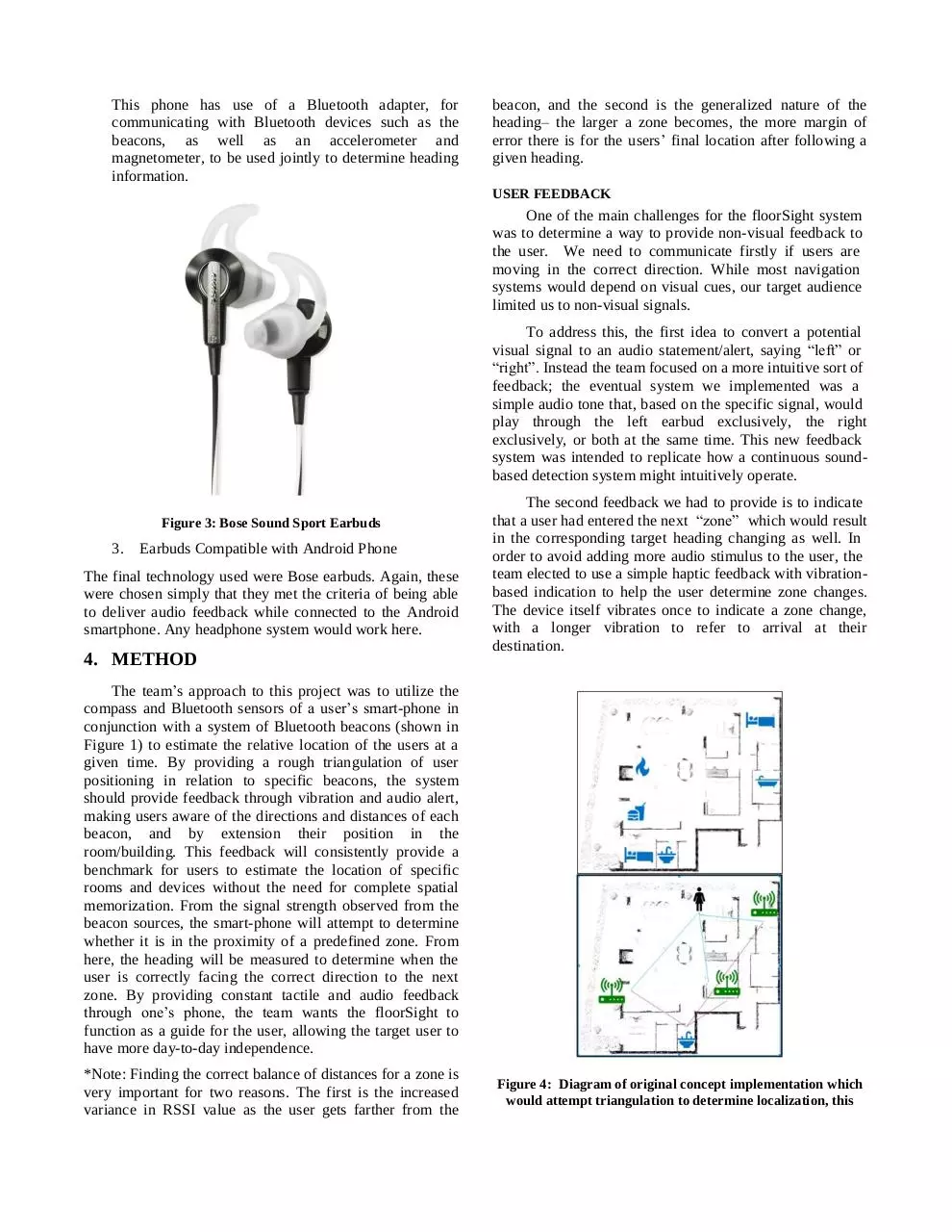
Figure 3: Bose Sound Sport Earbuds
3.
Earbuds Compatible with Android Phone
The final technology used were Bose earbuds. Again, these
were chosen simply that they met the criteria of being able
to deliver audio feedback while connected to the Android
smartphone. Any headphone system would work here.
4. METHOD
The second feedback we had to provide is to indicate
that a user had entered the next “zone” which would result
in the corresponding target heading changing as well. In
order to avoid adding more audio stimulus to the user, the
team elected to use a simple haptic feedback with vibrationbased indication to help the user determine zone changes.
The device itself vibrates once to indicate a zone change,
with a longer vibration to refer to arrival at their
destination.
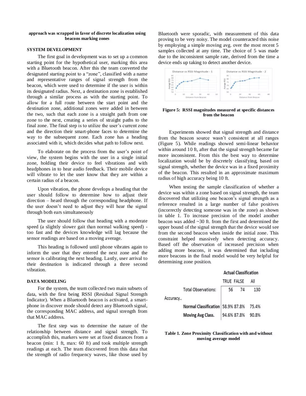
The team’s approach to this project was to utilize the
compass and Bluetooth sensors of a user’s smart-phone in
conjunction with a system of Bluetooth beacons (shown in
Figure 1) to estimate the relative location of the users at a
given time. By providing a rough triangulation of user
positioning in relation to specific beacons, the system
should provide feedback through vibration and audio alert,
making users aware of the directions and distances of each
beacon, and by extension their position in the
room/building. This feedback will consistently provide a
benchmark for users to estimate the location of specific
rooms and devices without the need for complete spatial
memorization. From the signal strength observed from the
beacon sources, the smart-phone will attempt to determine
whether it is in the proximity of a predefined zone. From
here, the heading will be measured to determine when the
user is correctly facing the correct direction to the next
zone. By providing constant tactile and audio feedback
through one’s phone, the team wants the floorSight to
function as a guide for the user, allowing the target user to
have more day-to-day independence.
*Note: Finding the correct balance of distances for a zone is
very important for two reasons. The first is the increased
variance in RSSI value as the user gets farther from the
Figure 4: Diagram of original concept implementation which
would attempt triangulation to determine localization, this
approach was scrapped in favor of discrete localization using
beacons marking zones
SYSTEM DEVELOPMENT
The first goal in development was to set up a common
starting point for the hypothetical user, marking this area
with a Bluetooth beacon. After this the team converted the
designated starting point to a “zone”, classified with a name
and representative ranges of signal strength from the
beacon, which were used to determine if the user is within
its designated radius. Next, a destination zone is established
through a similar process as with the starting point. To
allow for a full route between the start point and the
destination zone, additional zones were added in between
the two, such that each zone is a straight path from one
zone to the next, creating a series of straight paths to the
final zone. The final step is to utilize the user’s current zone
and the direction their smart-phone faces to determine the
way to the subsequent zone. Each zone has a heading
associated with it, which decides what path to follow next.
To elaborate on the process from the user’s point of
view, the system begins with the user in a single initial
zone, holding their device to feel vibrations and with
headphones in to hear audio feedback. Their mobile device
will vibrate to let the user know that they are within a
certain radius of a beacon.
Upon vibration, the phone develops a heading that the
user should follow to determine how to adjust their
direction – heard through the corresponding headphone. If
the user doesn’t need to adjust they will hear the signal
through both ears simultaneously
The user should follow that heading with a moderate
speed (a slightly slower gait than normal walking speed) too fast and the devices knowledge will lag because the
sensor readings are based on a moving average.
This heading is followed until phone vibrates again to
inform the user that they entered the next zone and the
sensor is calibrating the next heading. Lastly, user arrival to
their destination is indicated through a three second
vibration.
Bluetooth were sporadic, with measurement of this data
proving to be very noisy. The model counteracted this noise
by employing a simple moving avg. over the most recent 5
samples collected at any time. The choice of 5 was made
due to the inconsistent sample rate, derived from the time a
device ends up taking to detect another device.
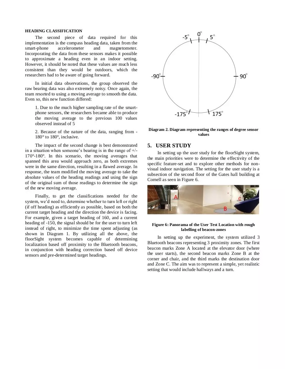
Figure 5: RSSI magnitudes measured at specific distances
from the beacon
Experiments showed that signal strength and distance
from the beacon source wasn’t consistent at all ranges
(Figure 5). While readings showed semi-linear behavior
within around 10 ft, after that the signal strength became far
more inconsistent. From this the best way to determine
localization would be by discretely classifying, based on
signal strength, whether the device was in a fixed proximity
of the beacon. This resulted in an approximate maximum
radius of high accuracy being 10 ft.
When testing the sample classification of whether a
device was within a zone based on signal strength, the team
discovered that utilizing one beacon’s signal strength as a
reference resulted in a large number of false positives
(incorrectly detecting someone was in the zone) as shown
in table 1. To increase precision of the model another
beacon was added ~30 ft. from the first and determined the
upper bound of the signal strength that the device would see
from the second beacon when inside the initial zone. This
constraint helped massively when detecting accuracy.
Based off the observation of increased precision when
adding more beacons, it was determined that including
more beacons in the final model would be very helpful for
determining zone position.
DATA MODELING
For the system, the team collected two main subsets of
data, with the first being RSSI (Residual Signal Strength
Indicator). When a Bluetooth beacon is activated, a smartphone in discover mode should detect any Bluetooth signal,
the corresponding MAC address, and signal strength from
that MAC address.
The first step was to determine the nature of the
relationship between distance and signal strength. To
accomplish this, markers were set at fixed distances from a
beacon (min: 1 ft, max: 60 ft) and took multiple strength
readings at each. The team discovered from this data that
the strength of radio frequency waves, like those used by
Table 1. Zone Proximity Classification with and without
moving average model
HEADING CLASSIFICATION
The second piece of data required for this
implementation is the compass heading data, taken from the
smart-phone
accelerometer
and
magnetometer.
Incorporating the data from these sensors makes it possible
to approximate a heading even in an indoor setting.
However, it should be noted that these values are much less
consistent than they would be outdoors, which the
researchers had to be aware of going forward.
In initial data observations, the group observed the
raw bearing data was also extremely noisy. Once again, the
team resorted to using a moving average to smooth the data.
Even so, this new function differed:
1. Due to the much higher sampling rate of the smartphone sensors, the researchers became able to produce
the moving average to the previous 100 values
observed instead of 5
2. Because of the nature of the data, ranging from 180° to 180°, inclusive.
The impact of the second change is best demonstrated
in a situation when someone’s bearing is in the range of +/170°-180°. In this scenario, the moving averages that
spanned this area would approach zero, as both extremes
were in the same direction, resulting in a flawed average. In
response, the team modified the moving average to take the
absolute values of the heading readings and using the sign
of the original sum of those readings to determine the sign
of the new moving average.
Finally, to get the classifications needed for the
system, we’d need to, determine whether to turn left or right
(if off heading) as efficiently as possible, based on both the
current target heading and the direction the device is facing.
For example, given a target heading of 160, and a current
heading of -150, the signal should be for the user to turn left
instead of right, to minimize the time spent adjusting (as
shown in Diagram 1. By utilizing all the above, the
floorSight system becomes capable of determining
localization based off proximity to the Bluetooth beacons,
in conjunction with heading correction based off device
sensors and pre-determined target headings.
Diagram 2. Diagram representing the ranges of degree sensor
values
5. USER STUDY
In setting up the user study for the floorSight system,
the main priorities were to determine the effectivity of the
specific feature-set and to explore other methods for nonvisual indoor navigation. The setting for the user study is a
subsection of the second floor of the Gates hall building at
Cornell as seen in Figure 6.
Figure 6: Panorama of the User Test Location with rough
labelling of beacon-zones
In setting up the experiment, the system utilized 3
Bluetooth beacons representing 3 proximity zones. The first
beacon marks Zone A located at the elevator door (where
the user starts), the second beacon marks Zone B at the
corner and chair, and the third marks the destination door
and Zone C. The aim was to represent a simple, yet realistic
setting that would include hallways and a turn.
Figure 7: The final beacon can be seen on top of the sign to the
bathroom
In the first several runs, volunteers to the study were
first explained the goal of the study and given a high-level
explanation of the system. After which, they were given
basic instructions to find the destination door from the
elevator while keeping their eyes covered. This was done to
serve as a sort of control proxy, and each trial was video
recorded. After the participants reached the destination,
they were brought to the beginning to try again using the
floorSight system. The basics of the system were explained
to them, including what sort of feedbacks there were and
general practices.
Figure 8: Graph displays the sensor data of the device used for
user testing for the third user trial
FINDINGS FROM PART I:
After explaining the general layout of the hallways
and giving cues to the destination such as being the second
door on the left, the team observed that all 4 users of the
first study reached the destination in 37 seconds on average
by using their hands to feel the wall as reference. The test
then consisted of transferring them back to the start and
giving them the floorSight system, then explaining its
functionality before asking them to attempt it once more,
following the vibration and audio cues.
For the first two users, they followed the audio cues
intuitively, with appropriate vibration feedback at the turn,
however were both led off course by the final heading
information and never reached the destination. The cause of
this inconsistency was determined to be the drop in heading
sensor accuracy while the user was in motion. Based on this
information the next two users were instructed to focus
finding the correct heading at each zone, but to rely less on
the audio signals when moving. This proved to be much
more effective as both users reached the destination in 45
and 39 seconds respectively.
Figure 9: Graph displays heading sensor data from the
floorSight device compared to target heading
Figure 6 shows the signal strengths, the respective
zone classified by the model, and heading data observed by
the device over the course of the trial. As Figure 6 shows,
the zone classification is consistent with what the team
would expect based on the signal strength data. In Figure 7
one can see the actual heading of the device deviated about
the target heading and the user made corrective adjustments
to remain “on-heading”. While the floorSight system saw
two successful runs, the risk of inconsistent heading data
became clear.
ADJUSTMENTS:
Despite these different cues, the team continued to
observe error prone trial runs. The team then moved to
make two major changes. The first of which, that there
would no longer be a control blind run to the destination, as
it gave the participants a prior knowledge of the layout and
the destination. Instead, they would use the floorSight
system from the start, and would not be told where the
destination would end up. This way, there would be no bias
in how users acted upon feedback from the system (such as
ignoring a directional cue because of prior knowledge of
the area). The second major change was that instead of a
constant audible feedback determined by the current
heading and target heading, the users would be given a
discrete instruction at each zone. The team observed from
control runs where the participants would use the wall and
other cues for guidance for nuances, and the hallway paths
were straight anyway. For example, at the elevator door, the
user would hear a single cue from their left ear, which was
explained to be directing a 90 degree turn in that direction
before continuing straight. Then upon entering the second
zone, they would receive another beep, through the left ear
to denote a left 90 degree turn. Finally, upon entering the
destination zone, they would hear another left beep, where
upon turning they would experience the prolonged vibration
representing arriving at the destination.
FINDINGS FROM PART II:
After adjusting the format of the user study, the team
then ran the experiment with 4 brand new volunteers who
were introduced to the system, newly adjusted audio
feedback and the ambiguous destination. Except for one,
each user could locate the destination correctly in 37
seconds on average. The user in exception was unable to
complete the course due to passing through zone B and not
receiving classification until too late due to the speed of
their walking a lagging sample rate. The final user also
received a cue that the destination was on the left upon
entering zone C early due to the classification model being
adjusted for a faster walking speed.
These explorative user studies left the team with
several strong takeaways. Firstly, heading data acquired
from the phone in an indoor environment while moving are
too inconsistent to use continuously for an effective
navigation system. After observing the ability of users to
locate the destination after given a high-level understanding
by using the wall as reference, the team determined that a
system that emphasized the reliable strength of determining
zone proximity with some discrete directional cues would
be optimal. The second was that users quickly found the
nature of the audio cues to suggest direction change to be
very intuitive, requiring very little assistance and quickly
adjusting to feedback. Combining this with the last
observation, the team found that providing discrete
directional cues upon entering different zones along the
way to the destination to yield much stronger and consistent
results of successful navigation. An additional advantage to
implementing this change is that the scalability of the
system for when multiple paths are established using
common beacons and paths.
Figure 10: User navigating the hallway without using vision or
assistance
Figure 11: User arriving at the destination while using
floorSight system, including earbuds
6. DISCUSSION
LIMITATIONS
As the team quickly observed, there were several
limitations on the reliability of the information that could be
gain through signal strength and heading data. For example,
the original intention was to use several Bluetooth beacons
situated throughout a building and then use the resulting
signal strengths as a mapping to distance from each beacon
and hen use that mapping to determine relative location
within the building. After researching and observing the
fickle nature of the radio frequency waves of Bluetooth, this
was determined to be infeasible. While from the data
discovery, the team could classify proximity to beacon (5
feet) with relative accuracy, it was still necessary to use
multiple beacon signal strengths to avoid false
classifications. The other limitation observed around
proximity classification was that surrounding classification
thresholds combined with walking speeds. As seen from the
user study, if one were to “loosen” the threshold to
accurately classify for a fast walking user, that model might
easily give an early classification for a slow-paced walker.
The second major limitation met was the
inconsistency of heading data indoors. While fairly accurate
outdoors, when combining movement and indoor
interference the data can easily be unreliable especially
when attempting to attain a smaller granularity of attaining
the direction from one beacon to another one a distance
away.
With adjustments to both limitations, the most
important limitation remains to be the battery draining
nature of the floorSight application. Due to the nature of
Bluetooth discovery, whenever a device is subject to
continually searching for nearby signals it is incredibly
demanding on the hardware. Should another party attempt
to replicate the floorSight system, it would be necessary to
determine a countermeasure or workaround for this to be a
frequently used technology.
gyroscope and accelerometer on the phone to a further
extent to attempt to classify steps and turning.
Another area or improvement would be to find a
simple method and model for consistent determinations of
signal strength ranges to use for classifying the proximity of
certain zones. Through the experiment, this was done ad
hoc by observing sensor data and using intuition, then hard
coding the ranges. For a system to be scalable, it would be
necessary for a non-tech savvy person to follow a simple
procedure that would automatically generate the needed
criteria.
Finally, while public buildings such as malls, offices
and restaurants were the original foci of locations where
floorSight to be impactful, they do show some drawbacks.
Businesses may not, on their own initiative, take on the
costs and efforts to establish floorSight beacons in their
locations, considering the small population of visually
impaired. It is from this intuition that the team would
refocus the primary target locations for a floorSight system
to be blind schools and universities, which would not only
have the highest and most consistent need, but also the best
opportunity to have a mutually beneficial relationship
through
development,
testing
and
deployment.
FUTURE WORK
In addition to limitations, the floorSight experiments
also gave many positive signals of potential. Auditory
signals through the left, right, or both ears proved to be as
intuitive as the team had hoped, showing its potential in a
more finalized product. Proximity classification showed
promise assuming a moderate walking speed as well, and
the vibration haptic feedback had the desired effect of
giving the user a sense of rough localization.
The success of future work should place emphasis not
on entirely replacing any method of navigation a visually
impaired person may use, but supplementing where it
falters. The evidence for this priority came from the switch
from using continuous heading feedback to simple discrete
instructions at turns and destinations, while allowing for
other intuitions such as feeling a wall for reference worked
well in tandem. While this new approach relieved the
system of the burden of unreliable heading data, it was also
tested in the context of hallway-like navigation where
references such as a wall were constant. Any further work
in this direction should seek to find a medium between
these directional navigation approaches as discrete signals
are scalable and reliable, but granular heading cues become
more necessary in open layouts.
The team believes that next steps in optimizing this
aspect of the system would be to explore use of the
Figure 12: Experimental logo for floorSight
7. CONCLUSION
This paper has now presented the team’s exploration of an
early prototype of a system to facilitate indoor navigation
for the visually-impaired. Not only has the following
exploration outlined shortcomings in technologies that
might be used for navigation, but it has also highlighted the
potential for a lightweight system using a layout of
Bluetooth beacons combined with proximity classification,
as well as intuitive approaches for conveying navigational
feedback through unobtrusive audio and vibration signals.
The floorSight system contributes to the blind accessibility
discussion by creating tangible results at a small scale, all
while using a flexible and scalable approach. While there
remains plenty of room for additional explorations in
classification, edge case exploration and reliability, this
paper presents a strong new platform for indoor
accessibility for the visually-impaired with realistic
deployment implications.
8. ACKNOWLEDGMENTS
We thank Dr. Aung and Alex Adams for their advice and
mentoring during the development of floorSight, in addition
to their guidance throughout the semester. We also thank
the individuals who were willing to assist us throughout the
testing and refining processes for this project.
9. REFERENCES
1. Bai, Y. B., Wu, S., Wu, H. R. & Zhang, K. (2012).
Overview of RFID-Based Indoor Positioning
Technology.. In C. Arrowsmith, C. Bellman, W.
Cartwright, K. Reinke, M. Shortis, M. Soto-Berelov &
L. S. Barranco (eds.), GSR, : CEUR-WS.org.
2. Bejuri, W. M. Y. W., Mohamad, M. M., & Radzi, R. Z.
R. M. (2015). Emergency rescue localization (ERL)
using GPS, wireless LAN and camera. International
Journal of Software Engineering and its Applications,
9(9), 217-232.
3. Giudice, N. A., & Legge, G. E. (2008). Blind navigation
and the role of technology. In A. Helal, M. Mokhtari &
B. Abdulrazak (Eds.), Engineering handbook of smart
technology for aging, disability, and independence, 479500.
4. Golledge, R. G., Klatzky & Loomis, J. M. (1998).
Navigation System for the Blind: Auditory Display
Modes and Guidance. Presence, 7(2), 193–203.
5. Huynh, P., & Yoo, M. (2016). VLC-Based Positioning
System for an Indoor Environment Using an Image
Sensor and an Accelerometer Sensor. Sensors (Basel,
Switzerland), 16(6), 783.
6. Kriz P., Maly F., and Kozel T. (2016). Improving Indoor
Localization Using Bluetooth Low Energy Beacons.
Mobile Information Systems, Volume 2016, 11 pages.
7. Weih L.M., Hassell J.B., Keeffe J. (2002). Assessment
of the impact of vision impairment. Invest Ophthalmol
Vis Sci. 43(4): 927–35.
8. Zhuang, Y., Yang, J., Li, Y., Qi, L., & El-Sheimy, N.
(2016). Smartphone-Based Indoor Localization with
Bluetooth Low Energy Beacons. Sensors (Basel,
Switzerland), 16(5), 596.
Download floorSight WriteUp Final
floorSight_WriteUp_Final.pdf (PDF, 533.53 KB)
Download PDF
Share this file on social networks
Link to this page
Permanent link
Use the permanent link to the download page to share your document on Facebook, Twitter, LinkedIn, or directly with a contact by e-Mail, Messenger, Whatsapp, Line..
Short link
Use the short link to share your document on Twitter or by text message (SMS)
HTML Code
Copy the following HTML code to share your document on a Website or Blog
QR Code to this page

This file has been shared publicly by a user of PDF Archive.
Document ID: 0000596375.