APSC258FinalReport (1) (PDF)
File information
This PDF 1.5 document has been generated by / Skia/PDF m59, and has been sent on pdf-archive.com on 18/05/2017 at 22:10, from IP address 50.68.x.x.
The current document download page has been viewed 701 times.
File size: 2.81 MB (48 pages).
Privacy: public file


File preview
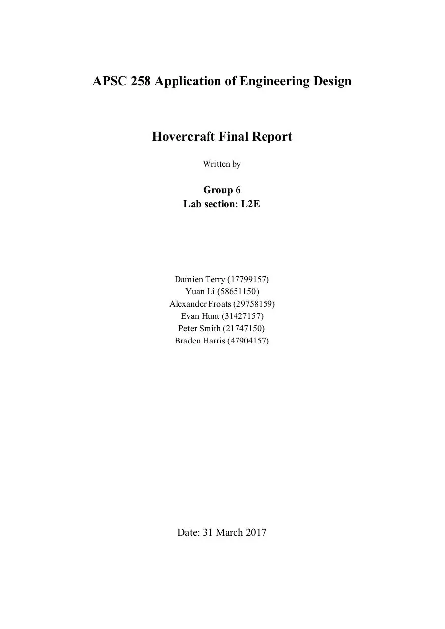
APSC 258 Application of Engineering Design
Hovercraft Final Report
Written by
Group 6
Lab section: L2E
Damien Terry (17799157)
Yuan Li (58651150)
Alexander Froats (29758159)
Evan Hunt (31427157)
Peter Smith (21747150)
Braden Harris (47904157)
Date: 31 March 2017
1
Table of Contents
Table of Figures
3
Executive Summary
4
1.0 Introduction
1.1 Background
1.2 Project Goal
1.3 Objectives / Constraints / Needs
5
5
5
5
2.0 Design Process
2.1 Engineering Aspects
2.2 Process Breakdown
2.2.1 Recognizing the Need
2.2.2 Defining the Problem
2.2.3 Planning the Project
2.2.4 Gathering Information
2.2.5 Conceptualising Alternative Approaches
2.2.6 Evaluating the Alternatives
2.2.7 Selecting the Preferred Alternative
2.2.8 Communicating the Design
2.2.9 Implementing the Preferred Design
2.3 Material Selection
2.4 SolidWorks Modeling
6
6
7
7
7
8
9
11
13
13
14
14
14
16
3.0 Physical Design
3.1 Structural
3.1.1 Frame
3.1.2 Part Allocation
3.1.3 Skirt
3.2 Mechanical
3.2.1 Lift and Thrust Fans
3.2.2 Rudders
3.2.3 Dropping Mechanism
3.3 Electrical
3.3.1 Fan and Rudder Wiring
3.3.2 Bluetooth and Arduino
19
19
19
20
21
23
23
24
26
28
29
30
4.0 Analysis
4.1 Selected Models
4.2 Weight distribution
33
33
34
5.0 Engineering tools used
35
2
5.1 Lift Analysis
5.2 Thrust Analysis
5.3 Analysis of Arduino system with Circuits
35
35
36
6.0 Conclusion
36
7.0 References (APA)
40
Appendix A - Design Drawings
41
Appendix B - Design Calculations
43
Appendix C - Material Billing
43
Appendix D - Meeting Minutes
44
3
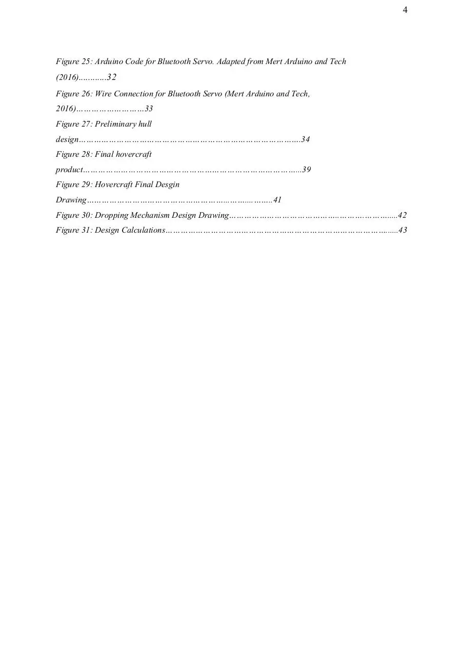
Table of Figures
Figure 1: QFD Chart Comparing Engineering and Customer
Requirements…………………………..…8
Figure 2: Gantt Chart Used to Track Project
Progress……………………………………………………....9
Figure 3. Lift variance vs. position
relation…………………………………………………………………..10
Figure 4: Styrofoam hovercraft design example..…………………………………………………………...
11
Figure 5: Design Process For Planned Hull Construction…………………………………………………14
Figure 6: Conceptual Hovercraft Model……………………………………………………………………...17
Figure 7: Rear View of Prototype
Design……………………………………………………………………..18
Figure 8: Front View of Prototype Design……………………………………………………………………18
Figure 9: Rear View of Final Design………………………………………………………………………….19
Figure 10: Front View of Final
Design………………………………………………………………………..19
Figure 11: Schematic of the Hull of the
Hovercraft……………………………………………………….…19
Figure 12: Hovercraft Part Allocation………………………………………………………………………..21
Figure 13: Final Hovercraft Skirt Design…………………………………………………………………….22
Figure 14: Fan positioning model……………………………………………………………………………..23
Figure 15: Fan Rudders…………………………………………………………………………………………24
Figure 16: Rudder front posts and rudder rotating
bar……………………………………………………..25
Figure 17: Rudder and rudder rotating
bar…………………………………………………………………..25
Figure 18: Side view……………………………………………………………………………………………..25
Figure 19: 3D view of whole rudder and rudder rotating mechanism……………………………………26
Figure 20: Model of dropping mechanism……………………………………………………………………27
Figure 21: Dropping mechanism with cone attachment…………………………………………………….28
Figure 22: Preliminary design drawing of the propulsion and steering system…………………………29
Figure 23: Schematic diagram of the final fan and rudder electrical design solution………………….30
Figure 24: Smartphone app for dropping mechanism control……………………………………………..31
4
Figure 25: Arduino Code for Bluetooth Servo. Adapted from Mert Arduino and Tech
(2016)............32
Figure 26: Wire Connection for Bluetooth Servo (Mert Arduino and Tech,
2016)………………………33
Figure 27: Preliminary hull
design…………………………………………………………………………….34
Figure 28: Final hovercraft
product…………………………………………………………………………...39
Figure 29: Hovercraft Final Desgin
Drawing………………………………………………...……....……..41
Figure 30: Dropping Mechanism Design Drawing……………………………………..……….……….....42
Figure 31: Design Calculations……………………………………………………………………………......43
5
Executive Summary
As the agriculture around the world is continuously advancing, farmers are constantly trying
to increase the efficiency of the process of delivering pesticides and have decided that a
hovercraft is the best solution. We have been assigned the task of designing and building a
hovercraft that is capable of performing the pesticide delivery that the farmers need.
Some major accomplishments documented in this report include:
-Developed a strong understanding of the functions and uses of hovercrafts
-Documented the detailed design process
-Evaluated the design problem and formulated relevant objectives and constraints
-Described in-depth key hovercraft components including the hull, wiring, dropping
mechanism, thrust and propulsion systems, skirt and steering system
-Separated the project into its relative engineering disciplines
-Created schematics and 3D models of preliminary designs, key components, and the final
product
-Explained choice of materials and the importance of material selection
Overall, the hovercraft project provided our team with a greater appreciation of the
complexity of hovercrafts and the many variables needed to be considered when undergoing
a comprehensive design process. The next step is to hopefully appear in the final competition
with the top 20 groups occurring on April 4, 2017.
6
1.0 Introduction
This report will outline the entire hovercraft project and what decisions led to the creation of
our design. With the available resources and equipment this is our team’s design from ideas
to the prototype and lastly the final product. Here is the breakdown of our choices and
changes throughout this project.
1.1 Background
A hovercraft is an air cushion vehicle that can travel over land, water, ice, and mud. Invented
in the 1900’s the hovercraft was created for military uses. It was great at carrying cargo with
efficiency and was built in mind of the military and is still used by them all around the world
today. It did not find much progress till the early 1950’s by Christopher Cockerell a british
engineer made a successful skirt using an idea from an experiment that involved a coffee can
and a tin of cat food. Thought not used commonly the hovercraft has a place with disaster
relief and military applications.
1.2 Project Goal
The objectives of this project are to use several methods to prepare, analyze, and build the
hovercraft design to achieve the purpose in maximizing the efficiency of the hovercraft. This
includes many styles such as brainstorming, scamper and mind mapping to create new and
innovative types of hovercraft designs. The design we chose is created to satisfy the basic
functional standards and the consumer’s requirements that they desire. Therefore many steps
have been taken to build a prototype before the final consumer product. As the goal is to
increase the total efficiency there are many ways to improve the pesticide delivery system.
1.3 Objectives / Constraints / Needs
Using a need statement you can find objectives and constraints to define and help focus on
what are the important aspects. The need statement we have decided to go with is “The
current pesticide delivery methods are not efficient enough” In this hovercraft design we
decided efficiency was one of the many things that was very important but is also restricted
by the speed that we can move. Another objective is the cost or expense of the final product,
7
the farmers need to be able to afford the hovercraft and all of its expenses. The constraint to
this however, is the quantity and the types of materials we will be using for the hovercraft as
higher quality items will be harder to obtain. Lastly another important factor is that the
pesticide drop needs to be accurate enough to be placed only where needed. The distance
from the drop point will determine its accuracy and will be restricted to point.
Need Statement: Current pesticide delivery methods are not efficient enough
Table 1: Design Objectives and Corresponding Constraints
Objective
Constraints
Units
Efficient
Speed
Seconds (s)
Inexpensive
Quantity and Type of
Dollars ($)
Material
Accurate
Distance from drop
Centimeters (cm)
point
2.0 Design Process
Extensive brainstorming, planning and preparation was key in the completion of this project.
To stay organised and on task we decided to track our process based on the design steps that
were covered in the APSC 258 lectures, and we worked on developing a deeper
understanding for the materials which would be used.mrch
2.1 Engineering Aspects
The building of the hovercraft will be divided into three components, mechanical, civil and
electrical. These are the main basis and what we will be focusing on throughout this project.
With the split of these three categories we can divide up how sections will be done. The
8
mechanical work will be the servo, skirt design, rudders and the dropping system that will be
used to drop the pesticides. Next will be the civil work which will include the structure of the
hovercraft, the placement of the components and the weight distribution. Finally the electrical
work will consist of the use of the arduino, the circuitry and the bluetooth connection for
wireless control.
2.2 Process Breakdown
2.2.1 Recognizing the Need
A group of farmers in the Okanagan valley are looking for better ways to deliver pesticides to
their crops. They are trying to increase the efficiency of the process of delivering pesticides,
and have decided that a hovercraft is the best solution. We have been assigned the task of
designing and building a hovercraft that can perform the pesticide delivery that the farmers
need. With this task in mind, our group devised a need statement with which our project was
based off. Our need statement is: “Current pesticide delivery methods are not efficient
enough.” The goal of this statement is to accurately recognize the need while remaining
simple yet effective. Once it was agreed upon, project progression continued.
2.2.2 Defining the Problem
After the need was established, the problem need to be defined. With this in mind, a problem
statement was conceptualised to fit the needs for the project. In order to create the best
problem statement possible, we decided it would be in our best interest to split up the design
into its relative engineering and customer requirements to get a better idea of what we needed
to accomplish. See figure 1 below for an organised table of our ideas in the form of a QFD
chart.
Download APSC258FinalReport (1)
APSC258FinalReport (1).pdf (PDF, 2.81 MB)
Download PDF
Share this file on social networks
Link to this page
Permanent link
Use the permanent link to the download page to share your document on Facebook, Twitter, LinkedIn, or directly with a contact by e-Mail, Messenger, Whatsapp, Line..
Short link
Use the short link to share your document on Twitter or by text message (SMS)
HTML Code
Copy the following HTML code to share your document on a Website or Blog
QR Code to this page

This file has been shared publicly by a user of PDF Archive.
Document ID: 0000598922.