ASCII EP02 (PDF)
File information
Title: PRT3 - ASCII Programming Guide
This PDF 1.4 document has been generated by FrameMaker 7.2 / Acrobat Distiller 8.1.0 (Windows), and has been sent on pdf-archive.com on 02/06/2017 at 12:04, from IP address 86.34.x.x.
The current document download page has been viewed 1207 times.
File size: 328.74 KB (32 pages).
Privacy: public file


File preview
PRT3 Printer Module:
ASCII Protocol Programming Instructions
We hope this product performs to your complete satisfaction. Should you have any
questions or comments, please visit www.paradox.com and send us your comments.
Table of Contents
Technical Specifications ............................................ 1
Panel Specifications .................................................. 1
Installation ................................................................. 3
Overview ................................................................... 3
Programming Sections .............................................. 3
Serial Port Setup ....................................................... 4
Virtual Input Programming ......................................... 4
Virtual PGM Programming ........................................ 7
ASCII Protocol ......................................................... 12
Printer Module to Digiplex Panel
Communication Status ......................................... 12
Commands sent to the Printer Module
from the Home Automation Module ...................... 12
Virtual Input Open ................................................... 12
Virtual Input Closed ................................................. 12
Request Area Status ............................................... 13
Request Zone Status ............................................... 13
Request Zone Label ................................................ 13
Request Area Label ................................................. 14
Request User Label ................................................. 14
Area Arm ................................................................. 14
Area Quick Arm ....................................................... 14
Area Disarm ............................................................. 15
Emergency Panic .................................................... 15
Medical Panic .......................................................... 15
Fire Panic ................................................................ 16
Smoke Reset ........................................................... 16
Utility Key ................................................................. 16
Commands sent from the Printer Module
to the Home Automation Module .......................... 16
Virtual PGM Events ................................................. 16
System Events ......................................................... 17
PGM Activation Event .............................................. 23
PGM Deactivation Option ........................................ 23
PGM Deactivation Event ......................................... 23
PGM Programming Table ........................................ 23
Technical Specifications
Parallel Port:
Serial Port:
Input Voltage:
Current Consumption:
Serial Port Baud Rates:
Event Buffer:
Compatibility:
Minimum 80 column printer
1 start bit, 8 data bit, no parity and 1 stop bit (8N1)
9 -16 Vdc
60mA maximum
2400, 9600, 19200 or 57600 bps
2048 events
Digiplex EVO48, EVO96, EVO192 control panels
DGP-848 control panel (V4.11 and up)
DGP-NE96 control panel (V1.60 and up)
Panel Specifications
Feature
Zones
Users
Areas
1
EVO48
EVO96
EVO192
DGP-848
DGP-NE96
48
96
4
96
999
8
192
999
8
48
96
4
96
999
8
Introduction
The PRT3 Printer Module can be used as an interface between a home automation module and your Digiplex system. When in home
automation mode, the Printer Module can receive and send commands to and from the home automation module and the Digiplex control
panel, linking your home automation capabilities with your security system.
The Printer Module features 16 onboard virtual inputs. These inputs are not related to any physical input on the module, but operate in the
same manner and are programmed in the same way as traditional zone inputs. A virtual input can be programmed to trigger a response
from the Digiplex control panel based on an event that has occurred within the home automation module. For example, your home
automation module may consist of a temperature sensor which you could associate with a virtual input. If the temperature fell to a certain
level, the home automation module would send a command to open/close one of the Printer Module’s virtual inputs and could trigger a
Digiplex zone programmed with a 24-hr. freeze to generate an alarm. Using virtual inputs to trigger events within the Digiplex control panel
involves associating the Printer Module’s virtual input to a zone or a keyswitch on the control panel. See “Virtual Input Programming” on
page 4.
The Printer Module also features 30 virtual PGMs for use with its home automation interface capabilities. These PGMs are not related to any
physical output on the module, but operate in the same manner and are programmed in the same way as a traditional PGM. A virtual PGM
can be used to trigger a response within the home automation module based on an event that has occurred within the Digiplex system. For
example, when a user uses the Digiplex system to disarm an area, this event could activate a virtual PGM on the Printer Module and trigger
a response within the home automation system, such as turning on a specific light on the premises. See “Virtual PGM Programming” on
page 7.
In order for the home automation module and the Digiplex control panel to communicate through the Printer Module, the home automation
module must be programmed to communicate using the ASCII Protocol. See “ASCII Protocol” on page 12.
For a complete list of the Printer Module’s event reporting features, see the Printer Module V1.0 (PRT3) Instructions.
2
Installation
The Printer Module is connected to the control panel’s combus. Connect the four terminals labeled red, black, green, and yellow of the
module to the corresponding terminals on the control panel as shown in Figure 2 on page 22. See the EVO or DGP-848 Reference &
Installation Manual for the maximum allowable installation distance from the control panel.
The home automation module must be connected directly to the Printer Module’s serial port (9-pin/ DB-9 connector). See Figure 2 on page
22 for an overview of the Printer Module’s connections, LEDs and connectors.
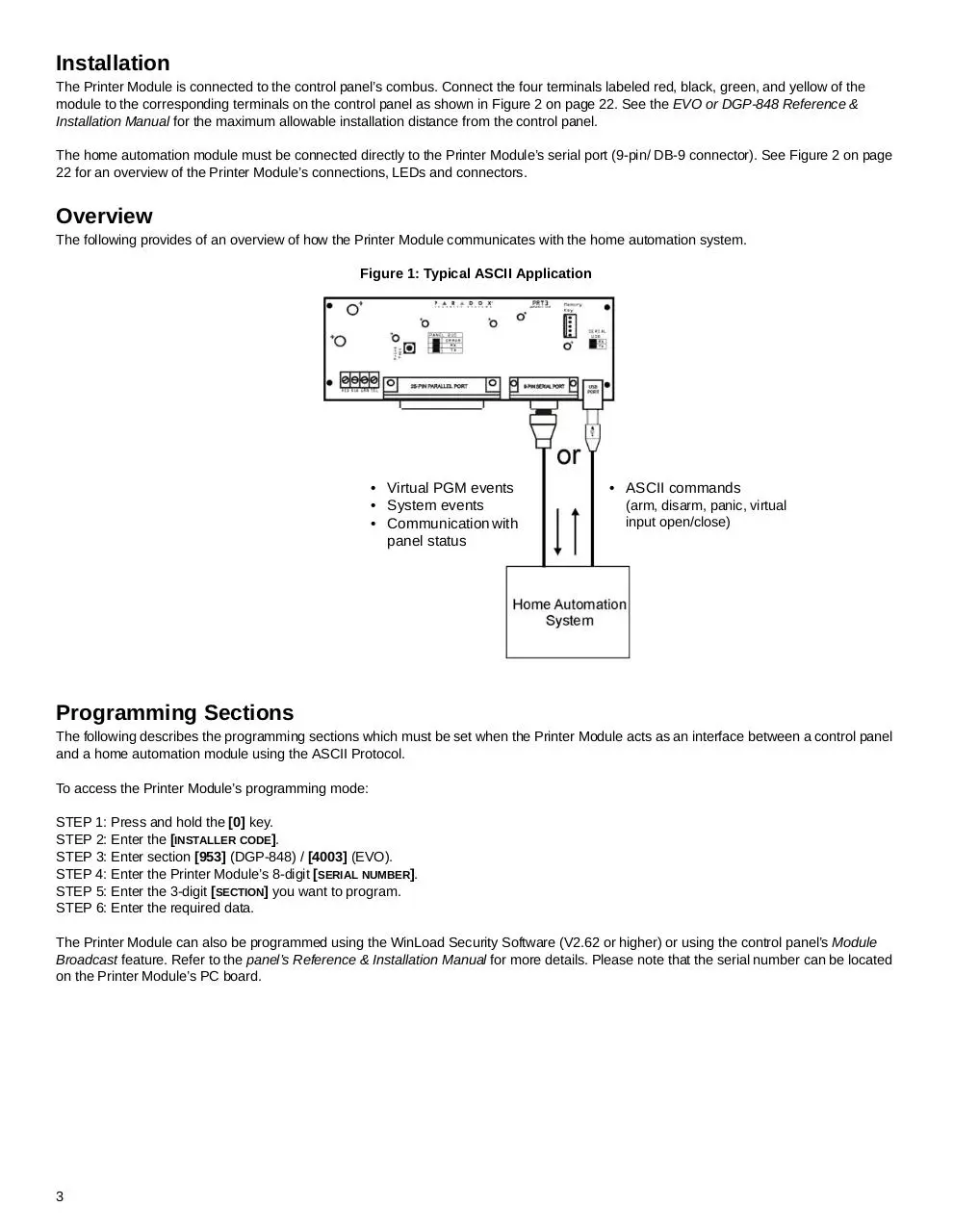
Overview
The following provides of an overview of how the Printer Module communicates with the home automation system.
Figure 1: Typical ASCII Application
• Virtual PGM events
• System events
• Communication with
panel status
• ASCII commands
(arm, disarm, panic, virtual
input open/close)
Programming Sections
The following describes the programming sections which must be set when the Printer Module acts as an interface between a control panel
and a home automation module using the ASCII Protocol.
To access the Printer Module’s programming mode:
STEP 1: Press and hold the [0] key.
STEP 2: Enter the [INSTALLER CODE].
STEP 3: Enter section [953] (DGP-848) / [4003] (EVO).
STEP 4: Enter the Printer Module’s 8-digit [SERIAL NUMBER].
STEP 5: Enter the 3-digit [SECTION] you want to program.
STEP 6: Enter the required data.
The Printer Module can also be programmed using the WinLoad Security Software (V2.62 or higher) or using the control panel’s Module
Broadcast feature. Refer to the panel’s Reference & Installation Manual for more details. Please note that the serial number can be located
on the Printer Module’s PC board.
3
Serial Port Setup
The following list the serial port programming options which must be set in order for the Printer Module to communicate with the home
automation module.
Section [016] - Option [1]
Enable Serial Port
When this option is ON (enabled), you can connect the home automation module directly to the Printer Module’s 9-pin serial or USB port.
Set option [4] to ON when using the Printer Module as an interface between a home automation module and the Digiplex system.
Section [016] - Options [2] & [3]
Baud Settings
This option allows you to set the Printer Module’s serial port baud rate. Set the Printer Module’s baud rate
to match that of the home automation module. Refer to the home automation module’s documentation to
determine what baud rate to set the Printer Module to.
U = default setting
Section [016] - Option [4]
Serial Port Usage
This option allows you to set the Printer Module’s serial port usage to either Event Reporting or Home Automation. To set the Printer Module
to Home Automation mode, set option [4] to ON .
Section [016] - Options [5] & [6]
Home Automation Options
This option allows you to select the home automation protocol for the Printer Module. To select
the ASCII Protocol, set options [5] and [6] to OFF .
U = default setting
For more information on the Clipsal C-Bus Protocol, see the C-Bus Programming Instructions on our website at paradox.com.
Virtual Input Programming
The home automation module can be programmed to open/close the Printer Module’s virtual inputs and generate activity within the Digiplex
system. The tables below offer an example of the virtual input programming sections which must be set for Virtual Input 1.
Section [700] : Virtual Input Options
Option
[1]
OFF
ON
U Disabled
N Enabled
Virtual Input Base Time Selection U Seconds
N Minutes
Enabling Virtual Input
[3] and [4] Virtual Input Close
[5]
4
Section
Data
Description
Default
__/__/__ (000 to 255) x Base Time
Virtual Input 1 Timer
005
[701]
Refer to the table below for a list of the programming sections for all virtual inputs.
Virtual
Input
Section
Virtual
Input
Section
Virtual
Input
Virtual
Input
Section
Section
1
[700] & [701]
5
[740] & [741]
9
[780] & [781]
13
[820] & [821]
2
[710] & [711]
6
[750] & [751]
10
[790] & [791]
14
[830] & [831]
3
[720] & [721]
7
[760] & [761]
11
[800] & [801]
15
[840] & [841]
4
[730] & [731]
8
[770] & [771]
12
[810] & [811]
16
[850] & [851]
The following describes the programming sections and options specific to the Printer Module’s virtual inputs. Use the programming tables to
document specific settings for all programmed virtual inputs.
Section [700] - Option [1]
Enabling Virtual Input Option
Each virtual input must be individually enabled. To enable the virtual input, set option [1] to ON.
U = default setting
Section
Virtual
Input
[1] OFF
[1] ON
Section
[1] OFF
[1] ON
[700]
1
U disabled
N enabled
Virtual
Input
[780]
9
U disabled
N enabled
[710]
2
U disabled
[790]
10
U disabled
[720]
3
U disabled
[800]
11
U disabled
[730]
4
U disabled
[810]
12
U disabled
[740]
5
U disabled
[820]
13
U disabled
[750]
6
U disabled
[830]
14
U disabled
[760]
7
U disabled
[840]
15
U disabled
[770]
8
U disabled
[850]
16
U disabled
N enabled
N enabled
N enabled
N enabled
N enabled
N enabled
N enabled
N enabled
N enabled
N enabled
N enabled
N enabled
N enabled
N enabled
Section [700] - Options [3] and [4]
Virtual Input Close Option
The virtual input can be closed by receiving a virtual input close command and/or after a timer
elapses. This option determines how the virtual input will close.
U = default setting
Section
5
Virtual Input
[3] OFF / [4] OFF
[700]
1
U close command
[710]
2
U close command
[720]
3
U close command
[730]
4
U close command
[740]
5
U close command
[750]
6
U close command
[760]
7
U close command
[770]
8
U close command
[780]
9
U close command
[3] ON / [4] OFF
N virtual input timer
N virtual input timer
N virtual input timer
N virtual input timer
N virtual input timer
N virtual input timer
N virtual input timer
N virtual input timer
N virtual input timer
[3] OFF / [4] ON
N close command or virtual input timer
N close command or virtual input timer
N close command or virtual input timer
N close command or virtual input timer
N close command or virtual input timer
N close command or virtual input timer
N close command or virtual input timer
N close command or virtual input timer
N close command or virtual input timer
[790]
10
U close command
[800]
11
U close command
[810]
12
U close command
[820]
13
U close command
[830]
14
U close command
[840]
15
U close command
[850]
16
U close command
N virtual input timer
N close command or virtual input timer
N virtual input timer
N close command or virtual input timer
N virtual input timer
N close command or virtual input timer
N virtual input timer
N close command or virtual input timer
N virtual input timer
N close command or virtual input timer
N virtual input timer
N close command or virtual input timer
N virtual input timer
N close command or virtual input timer
Section [701]
Virtual Input Timers
If the virtual input is set to follow its Virtual Input Timer, the entered value represents the amount of time that the virtual input will remain
open. To program the Virtual Input Timer, enter a 3-digit value from 000 to 255. Depending on the Virtual Input Base Time (see below), the
Virtual Input Timer will either be in seconds or minutes.
Section
Virtual Input
Data
Section
Virtual Input
Data
[701]
1
__/__/__ (000 to 255) x Base time
[781]
9
__/__/__ (000 to 255) x Base time
[711]
2
__/__/__ (000 to 255) x Base time
[791]
10
__/__/__ (000 to 255) x Base time
[721]
3
__/__/__ (000 to 255) x Base time
[801]
11
__/__/__ (000 to 255) x Base time
[731]
4
__/__/__ (000 to 255) x Base time
[811]
12
__/__/__ (000 to 255) x Base time
[741]
5
__/__/__ (000 to 255) x Base time
[821]
13
__/__/__ (000 to 255) x Base time
[751]
6
__/__/__ (000 to 255) x Base time
[831]
14
__/__/__ (000 to 255) x Base time
[761]
7
__/__/__ (000 to 255) x Base time
[841]
15
__/__/__ (000 to 255) x Base time
[771]
8
__/__/__ (000 to 255) x Base time
[851]
16
__/__/__ (000 to 255) x Base time
Section [700] - Option [5]
Virtual Input Base Time Selection
If option [5] is OFF, the value programmed for the Virtual Input Timer will be in seconds. If option [5] is ON, the Virtual Input Timer will be in
minutes. The following table lists the base time sections and their respective virtual inputs.
U = default setting
Section
Virtual
Input
[5] OFF
[5] ON
Section
[700]
1
U seconds
N minutes
[710]
2
U seconds
[720]
3
U seconds
[730]
4
U seconds
[740]
5
U seconds
[750]
6
U seconds
[760]
7
U seconds
[770]
8
U seconds
N minutes
N minutes
N minutes
N minutes
N minutes
N minutes
N minutes
Virtual
Input
[5] OFF
[5] ON
[780]
9
U seconds
N minutes
[790]
10
U seconds
[800]
11
U seconds
[810]
12
U seconds
[820]
13
U seconds
[830]
14
U seconds
[840]
15
U seconds
[850]
16
U seconds
N minutes
N minutes
N minutes
N minutes
N minutes
N minutes
N minutes
6
Virtual PGM Programming
The Printer Module supports up to 30 virtual PGMs which are not related to any physical output on the module, but operate in the same
manner and are programmed in the same way as traditional PGMs. The tables below offer an example of the virtual PGM programming
sections which must be set for virtual PGM 1.
Section [100] : Virtual PGM Options
Option
OFF
ON
[1] and [2] Virtual PGM Deactivation
[3]
Virtual PGM Base Time Selection U Seconds
[4]
U Message
not resent
Virtual PGM Resend
Section
[101]
N Minutes
N Message
resent
Data
Description
Default
__/__/__ (000 to 255) x Base Time
Virtual PGM 1 Timer
005
Event Group
Feature Group
Section
Section
Start #
Section
End #
Section
Virtual PGM Activation
[102]
__/__/__
[103]
__/__/__
[104]
__/__/__
[105]
__/__/__
Virtual PGM Deactivation
[106]
__/__/__
[107]
__/__/__
[108]
__/__/__
[109]
__/__/__
Refer to the table below for a list of the programming sections for all virtual PGMs.
Virtual
PGM
Section
Virtual
PGM
Section
Virtual
PGM
Section
Virtual
PGM
Section
Virtual
PGM
Section
1
[100] - [109]
7
[160] - [169]
13
[220] - [229]
19
[280] - [289]
25
[340] - [349]
2
[110] - [119]
8
[170] - [179]
14
[230] - [239]
20
[290] - [299]
26
[350] - [359]
3
[120] - [129]
9
[180] - [189]
15
[240] - [249]
21
[300] - [309]
27
[360] - [369]
[370] - [379]
4
[130] - [139]
10
[190] - [199]
16
[250] - [259]
22
[310] - [319]
28
5
[140] - [149]
11
[200] - [209]
17
[260] - [269]
23
[320] - [329]
29
[380] - [389]
6
[150] - [159]
12
[210] - [219]
18
[270] - [279]
24
[330] - [339]
30
[390] - [399]
For more information on PGM programming, see “Appendix 1: Programming PGMs” on page 23.
The following describes the programming sections and options specific to the Printer Module’s virtual PGMs. Use the programming tables to
document specific settings for all programmed virtual PGMs.
Section [100] - Options [1] and [2]
Virtual PGM Deactivation Option
When the Virtual PGM Activation Event occurs, this option determines when the virtual PGM will
return to its normal state (deactivate). Depending on the programmed value, the virtual PGM can stay
activated indefinitely. It can also deactivate following a virtual deactivation event (see “Virtual PGM
Deactivation Event” on page 11) and/or after the Virtual PGM Timer has elapsed (see “Virtual PGM
Timers” on page 8).
7
U = default setting
Section
Virtual
PGM
[100]
1
[110]
2
[120]
3
[130]
4
[140]
5
[150]
6
[160]
7
[170]
8
[180]
9
[190]
10
[200]
11
[210]
12
[220]
13
[230]
14
[240]
15
[250]
16
[260]
17
[270]
18
[280]
19
[290]
20
[300]
21
[310]
22
[320]
23
[330]
24
[340]
25
[350]
26
[360]
27
[370]
28
[380]
29
[390]
30
[1] OFF / [2] OFF
[1] ON / [2] OFF
[1] OFF / [2] ON
[1] ON / [2] ON
N no deactivation
U deactivation event
N virtual PGM timer
N deactivation event or virtual PGM timer
N virtual PGM timer
N deactivation event or virtual PGM timer
N no deactivation
N no deactivation
N no deactivation
N no deactivation
N no deactivation
N no deactivation
N no deactivation
N no deactivation
N no deactivation
N no deactivation
N no deactivation
N no deactivation
N no deactivation
N no deactivation
N no deactivation
N no deactivation
N no deactivation
N no deactivation
N no deactivation
N no deactivation
N no deactivation
N no deactivation
N no deactivation
N no deactivation
N no deactivation
N no deactivation
N no deactivation
N no deactivation
N no deactivation
U deactivation event
U deactivation event
U deactivation event
U deactivation event
U deactivation event
U deactivation event
U deactivation event
U deactivation event
U deactivation event
U deactivation event
U deactivation event
U deactivation event
U deactivation event
U deactivation event
U deactivation event
U deactivation event
U deactivation event
U deactivation event
U deactivation event
U deactivation event
U deactivation event
U deactivation event
U deactivation event
U deactivation event
U deactivation event
U deactivation event
U deactivation event
U deactivation event
U deactivation event
N virtual PGM timer
N virtual PGM timer
N virtual PGM timer
N virtual PGM timer
N virtual PGM timer
N virtual PGM timer
N deactivation event or virtual PGM timer
N deactivation event or virtual PGM timer
N deactivation event or virtual PGM timer
N deactivation event or virtual PGM timer
N deactivation event or virtual PGM timer
N deactivation event or virtual PGM timer
N virtual PGM timer
N deactivation event or virtual PGM timer
N virtual PGM timer
N deactivation event or virtual PGM timer
N virtual PGM timer
N virtual PGM timer
N virtual PGM timer
N virtual PGM timer
N virtual PGM timer
N virtual PGM timer
N virtual PGM timer
N virtual PGM timer
N deactivation event or virtual PGM timer
N deactivation event or virtual PGM timer
N deactivation event or virtual PGM timer
N deactivation event or virtual PGM timer
N deactivation event or virtual PGM timer
N deactivation event or virtual PGM timer
N deactivation event or virtual PGM timer
N deactivation event or virtual PGM timer
N virtual PGM timer
N deactivation event or virtual PGM timer
N virtual PGM timer
N deactivation event or virtual PGM timer
N virtual PGM timer
N virtual PGM timer
N virtual PGM timer
N virtual PGM timer
N virtual PGM timer
N virtual PGM timer
N virtual PGM timer
N virtual PGM timer
N virtual PGM timer
N virtual PGM timer
N deactivation event or virtual PGM timer
N deactivation event or virtual PGM timer
N deactivation event or virtual PGM timer
N deactivation event or virtual PGM timer
N deactivation event or virtual PGM timer
N deactivation event or virtual PGM timer
N deactivation event or virtual PGM timer
N deactivation event or virtual PGM timer
N deactivation event or virtual PGM timer
N deactivation event or virtual PGM timer
Section [101]
Virtual PGM Timers
If the virtual PGM is set to follow its Virtual PGM Timer (see “Virtual PGM Deactivation Option” on page 7), the entered value represents the
amount of time that the virtual PGM will remain activated. To program the Virtual PGM Timer, enter a 3-digit value from 000 to 255.
Depending on the Virtual PGM Base Time (see below), the Virtual PGM Timer will either be in seconds or minutes.
Section
Virtual PGM
Data
Section
Virtual PGM
Data
[101]
1
__/__/__ (000 to 255) x Base time
[251]
16
__/__/__ (000 to 255) x Base time
[111]
2
__/__/__ (000 to 255) x Base time
[261]
17
__/__/__ (000 to 255) x Base time
[121]
3
__/__/__ (000 to 255) x Base time
[271]
18
__/__/__ (000 to 255) x Base time
[131]
4
__/__/__ (000 to 255) x Base time
[281]
19
__/__/__ (000 to 255) x Base time
[141]
5
__/__/__ (000 to 255) x Base time
[291]
20
__/__/__ (000 to 255) x Base time
[151]
6
__/__/__ (000 to 255) x Base time
[301]
21
__/__/__ (000 to 255) x Base time
[161]
7
__/__/__ (000 to 255) x Base time
[311]
22
__/__/__ (000 to 255) x Base time
[171]
8
__/__/__ (000 to 255) x Base time
[321]
23
__/__/__ (000 to 255) x Base time
[181]
9
__/__/__ (000 to 255) x Base time
[331]
24
__/__/__ (000 to 255) x Base time
[191]
10
__/__/__ (000 to 255) x Base time
[341]
25
__/__/__ (000 to 255) x Base time
8
Download ASCII-EP02
ASCII-EP02.pdf (PDF, 328.74 KB)
Download PDF
Share this file on social networks
Link to this page
Permanent link
Use the permanent link to the download page to share your document on Facebook, Twitter, LinkedIn, or directly with a contact by e-Mail, Messenger, Whatsapp, Line..
Short link
Use the short link to share your document on Twitter or by text message (SMS)
HTML Code
Copy the following HTML code to share your document on a Website or Blog
QR Code to this page

This file has been shared publicly by a user of PDF Archive.
Document ID: 0000606475.