ISTA UserManual en GB (PDF)
File information
Title: Dokumenttitel
Author: Riemann Robert
This PDF 1.5 document has been generated by Microsoft® Word 2013, and has been sent on pdf-archive.com on 03/06/2017 at 16:29, from IP address 45.63.x.x.
The current document download page has been viewed 14001 times.
File size: 2.96 MB (69 pages).
Privacy: public file


File preview
ISTA User Guide
ISTA version
4.05
Date
March 2017
BMW Group
Page 2
ISTA User Guide, ISTA version 4.05
of 69
Table of contents
Table of contents ............................................................................................................................................... 2
1
Introduction ................................................................................................................................................. 4
1.1
The workshop system ISTA (Integrated Service Technical Application) ............................................ 4
1.1.1
Diagnosis ................................................................................................................................... 4
1.1.2
Programming ............................................................................................................................. 4
1.1.3
Interfaces ................................................................................................................................... 4
1.2
Data exchange between ISTA and other systems via IPS ................................................................. 5
1.3
Marque separation .............................................................................................................................. 5
1.4
General operation of the application ................................................................................................... 5
1.4.1
Operations bar ........................................................................................................................... 6
1.4.2
Toolbar ....................................................................................................................................... 6
1.4.3
header ........................................................................................................................................ 7
1.4.4
Navigation area .......................................................................................................................... 7
1.4.5
Working range............................................................................................................................ 7
1.4.6
Hint Line ..................................................................................................................................... 7
1.4.7
Action line .................................................................................................................................. 7
1.4.8
Options for text entry (on-screen keyboard) .............................................................................. 7
1.5
Meaning of the symbols used in the document ................................................................................... 8
1.6
Important safety information ................................................................................................................ 9
1.7
Referenced documents ....................................................................................................................... 9
2
Installation and software updates ............................................................................................................. 10
3
Operation .................................................................................................................................................. 11
3.1
Starting the application ...................................................................................................................... 11
3.2
Starting the application (motorcycles) ............................................................................................... 12
3.3
Identifying a vehicle ........................................................................................................................... 12
3.3.1
Editing several operations at the same time ............................................................................ 13
3.3.2
Selecting a vehicle via "Read out vehicle data" ....................................................................... 15
3.4
Testing vehicle .................................................................................................................................. 17
3.5
Show fault memory............................................................................................................................ 18
3.6
Displaying fault memory (motorcycles) ............................................................................................. 19
3.7
Processing the test plan .................................................................................................................... 20
3.8
Programming the vehicle .................................................................................................................. 22
3.8.1
Preparation for the programming ............................................................................................. 24
3.8.2
Software update ....................................................................................................................... 26
BMW Group
Page 3
ISTA User Guide, ISTA version 4.05
3.8.3
Control unit replacement .......................................................................................................... 31
3.8.4
Vehicle modification ................................................................................................................. 34
3.8.5
Measures plan ......................................................................................................................... 42
3.8.6
Subsequent evaluation and final service functions.................................................................. 45
3.8.7
Final report ............................................................................................................................... 46
3.8.8
Execution stop ......................................................................................................................... 47
3.8.9
Enabling codes ........................................................................................................................ 49
3.8.10
Control unit repair measures ................................................................................................... 52
3.8.11
Problem handling ..................................................................................................................... 53
3.9
4
5
6
of 69
Updating or activating navigation maps ............................................................................................ 54
3.9.1
Function selection .................................................................................................................... 54
3.9.2
Updating navigation maps (with or without activation) ............................................................ 55
3.9.3
Activation of an existing navigation map ................................................................................. 58
3.10
Printing process report ...................................................................................................................... 58
3.11
Terminate operation .......................................................................................................................... 59
3.12
Continuing an operation .................................................................................................................... 60
Feedback .................................................................................................................................................. 62
4.1
Support .............................................................................................................................................. 62
4.2
Content feedback .............................................................................................................................. 62
Symbols .................................................................................................................................................... 64
5.1
Toolbar .............................................................................................................................................. 64
5.2
Operations bar................................................................................................................................... 65
Appendix ................................................................................................................................................... 66
6.1
Information types in ISTA documents ............................................................................................... 66
List of tables ..................................................................................................................................................... 67
List of figures ................................................................................................................................................... 68
BMW Group
Page 4
ISTA User Guide, ISTA version 4.05
1
of 69
Introduction
Operation, display masks and the ISTA workshop system functions are described in this document. The user
manual is addressed primarily to service technicians working in the workshop environment.
1.1 The workshop system ISTA (Integrated Service Technical Application)
ISTA is the diagnosis and programming application for BMW Group vehicles in the worldwide Retailer
Organisation
1.1.1 Diagnosis
Vehicle identification for specific vehicle management
Information research for repair and maintenance
Guided troubleshooting
Software repair
1.1.2 Programming
Software update
Control unit replacement
Retrofit/conversion
1.1.3 Interfaces
1.1.3.1 IMIB (Integrated Measurement Interface Box)
The IMIB is a powerful measuring device. It contains several measuring devices, which can adopt the
behaviour of an oscilloscope and a digital multimeter. The IMIB contains controlled current and voltage
sources for output of voltages and signals.
It can be used without a connection to ISTA as a Standalone measuring device or also in connection with
ISTA. Possible connection types are LAN or WLAN.
The IMIB can be operated in two ways in connection with ISTA:
free measuring technique
embedded in test sequences as guided troubleshooting
In the free measuring technique you can make manual adjustments in the corresponding input screens after
establishing the connection with the IMIB, in order to influence the display of current measuring results.
In the guided measuring technique, the measurement system is automatically set using program instructions
in the test module. Results are shown in specific masks and evaluated by the program.
BMW Group
Page 5
ISTA User Guide, ISTA version 4.05
of 69
1.1.3.2 ICOM (Integrated Communication Optical Module)
ICOM is a communication device (VCI, Vehicle Communication Interface) and represents the diagnostic
interface of the vehicle. It is connected to the vehicle and can then be connected via the ISTA connection
manager. ISTA can communicate with the vehicle, for instance for automatic vehicle identification or carrying
out test sequences.
1.2 Data exchange between ISTA and other systems via IPS
The IPS (ISPI Process Services) are a Windows service offering interfaces for the ISPI Next applications
AIR, ISTA, ISPA Next, and ISPA Mobile so that shared data can be accessed across devices and
applications. The service ensures that the exchange of data between applications is allowed. If the service
on the internal network of the outlet is not active, the use of data, depending on the application, is severely
limited. Only one service per data storage can be active at a time.
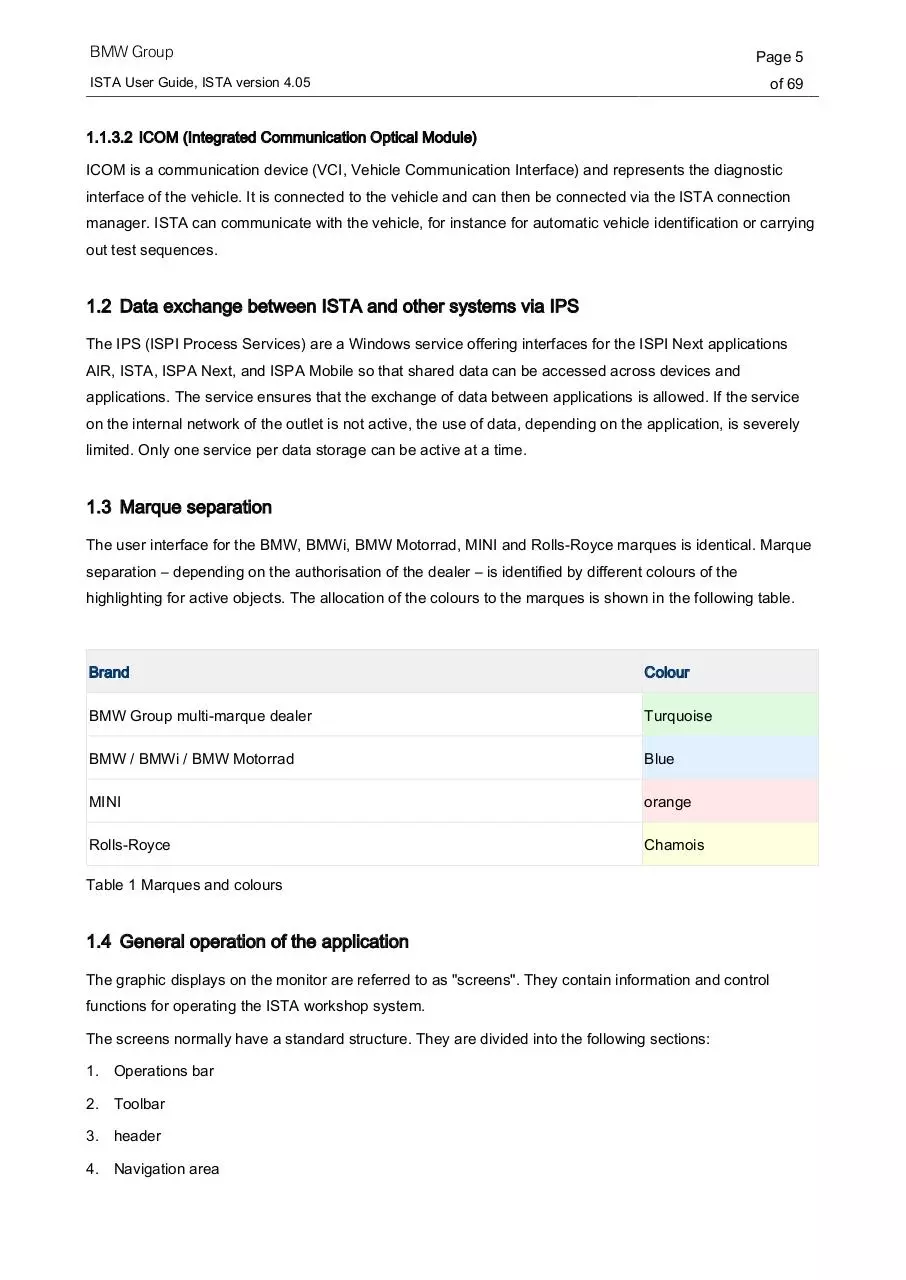
1.3 Marque separation
The user interface for the BMW, BMWi, BMW Motorrad, MINI and Rolls-Royce marques is identical. Marque
separation – depending on the authorisation of the dealer – is identified by different colours of the
highlighting for active objects. The allocation of the colours to the marques is shown in the following table.
Brand
Colour
BMW Group multi-marque dealer
Turquoise
BMW / BMWi / BMW Motorrad
Blue
MINI
orange
Rolls-Royce
Chamois
Table 1 Marques and colours
1.4 General operation of the application
The graphic displays on the monitor are referred to as "screens". They contain information and control
functions for operating the ISTA workshop system.
The screens normally have a standard structure. They are divided into the following sections:
1. Operations bar
2. Toolbar
3. header
4. Navigation area
BMW Group
ISTA User Guide, ISTA version 4.05
Page 6
of 69
5. Working range
6. Hint Line
7. Action line
Figure 1 Control and indication ranges
1.4.1 Operations bar
The operations bar itself is only active during an active operation. All the functions in this bar only affect the
current operation.
1.4.2 Toolbar
The symbol bar is shown in all screen masks. The functions that can be called up via the individual icons are
described in chapter Symbols.
BMW Group
Page 7
ISTA User Guide, ISTA version 4.05
of 69
1.4.3 header
The vehicle identification number and the basic features of the identified vehicle are shown in the header.
The vehicle identification number is only displayed if the vehicle has been identified by entering or reading
out its vehicle identification number.
1.4.4 Navigation area
You can navigate to the individual functions of the workshop system via
main menu (first line),
submenu (second line) and the
tabs.
The tabs selected are highlighted in the respective marque colour.
1.4.5 Working range
Further options and information can be found here. A white arrow pointing up or down identifies the column
that is used for sorting a selection list.
1.4.6 Hint Line
The bottom part of the working area may also contain a comment line in which you will receive additional
information.
1.4.7 Action line
Buttons are shown here depending on the workspace.
1.4.8 Options for text entry (on-screen keyboard)
In various masks, it can be necessary to enter text or characters. In general, this can be done using a
keyboard. Click the "keyboard" button to show the display keyboard. Only keys that are necessary to make
valid entries at the respective function step are enabled on the on-screen keyboard. Impermissible
characters cannot be selected on the display keyboard.
A second click on the "Keyboard" button hides the on-screen keyboard.
BMW Group
Page 8
ISTA User Guide, ISTA version 4.05
of 69
Figure 2 Example of a display keyboard: Entering search terms
1.5 Meaning of the symbols used in the document
The symbols below used in this User Manual have the following meanings:
The symbol indicates “Note” and “Warning”. It represents important text passages to avoid
unexpected results when dealing with ISTA and notes on actions that may lead to personal injury
or property damage.
The "INFORMATION" symbol refers to further documentation.
BMW Group
Page 9
ISTA User Guide, ISTA version 4.05
of 69
1.6 Important safety information
Before using the ISTA workshop system, you should familiarise yourself with the relevant safety regulations
and then read and comply with the notes contained in these instructions.
Certain functions in ISTA can trigger off activations of components in the connected vehicle.
Before activating components, make sure that there are no persons in the danger area. Read and
comply with the general safety provisions.
1.7 Referenced documents
NAME
Description
ISPI Administrator guide
Contains information intended primarily for the ISPI administrator.
ISPI Planning Guide
Required infrastructure and hardware requirements
Table 2 Referenced documents
Download ISTA UserManual en-GB
ISTA_UserManual_en-GB.pdf (PDF, 2.96 MB)
Download PDF
Share this file on social networks
Link to this page
Permanent link
Use the permanent link to the download page to share your document on Facebook, Twitter, LinkedIn, or directly with a contact by e-Mail, Messenger, Whatsapp, Line..
Short link
Use the short link to share your document on Twitter or by text message (SMS)
HTML Code
Copy the following HTML code to share your document on a Website or Blog
QR Code to this page

This file has been shared publicly by a user of PDF Archive.
Document ID: 0000606896.