Motorola WB3025A (PDF)
File information
Title: PTP 600 Series User Guide
Author: Motorola
This PDF 1.4 document has been generated by Acrobat PDFMaker 8.1 for Word / Acrobat Distiller 8.3.1 (Windows), and has been sent on pdf-archive.com on 09/07/2017 at 20:55, from IP address 216.145.x.x.
The current document download page has been viewed 1070 times.
File size: 100.64 KB (6 pages).
Privacy: public file


File preview
PTP 600 Series User Guide
Powered indoor unit (PIDU Plus)
Powered indoor unit (PIDU Plus)
This section describes the PIDU Plus and its interfaces.
PIDU Plus description
The PIDU Plus generates the ODU supply voltage from the mains supply (or from an
external DC source) and injects this supply voltage into the ODU.
The PIDU Plus is connected to the ODU and network equipment using CAT5e cable
with RJ45 connectors. Refer to Cabling and lightning protection on page 1-17.
The ODU for the PTP 600 Series should only be deployed using the supplied PIDU Plus
PTP 300/500/600 Series.
CAUTION
Care should be taken not to connect equipment other than an ODU, LPU or
PTP-SYNC for the PTP 600 Series to a PIDU Plus ODU port, as equipment
damage may occur. The PIDU Plus PTP 300/500/600 Series is not
interchangeable with the PIDU Plus PTP 400 Series.
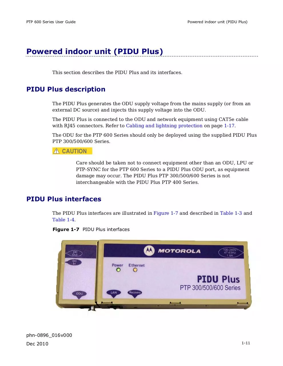
PIDU Plus interfaces
The PIDU Plus interfaces are illustrated in Figure 1-7 and described in Table 1-3 and
Table 1-4.
Figure 1-7 PIDU Plus interfaces
phn-0896_016v000
Dec 2010
1-11
Powered indoor unit (PIDU Plus)
Chapter 1 Product description
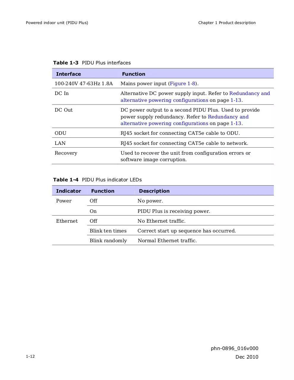
Table 1-3 PIDU Plus interfaces
Interface
Function
100-240V 47-63Hz 1.8A
Mains power input (Figure 1-8).
DC In
Alternative DC power supply input. Refer to Redundancy and
alternative powering configurations on page 1-13.
DC Out
DC power output to a second PIDU Plus. Used to provide
power supply redundancy. Refer to Redundancy and
alternative powering configurations on page 1-13.
ODU
RJ45 socket for connecting CAT5e cable to ODU.
LAN
RJ45 socket for connecting CAT5e cable to network.
Recovery
Used to recover the unit from configuration errors or
software image corruption.
Table 1-4 PIDU Plus indicator LEDs
Indicator
Function
Description
Power
Off
No power.
On
PIDU Plus is receiving power.
Off
No Ethernet traffic.
Blink ten times
Correct start up sequence has occurred.
Blink randomly
Normal Ethernet traffic.
Ethernet
phn-0896_016v000
1-12
Dec 2010
PTP 600 Series User Guide
Powered indoor unit (PIDU Plus)
Figure 1-8 PIDU Plus power input
Redundancy and alternative powering configurations
The PTP 600 Series can be powered from an external DC source and can be provided
with power supply redundancy as follows:
x
External DC supply only (Figure 1-10): This configuration is for use where there
is no mains supply.
x
External DC supply and AC supply (Figure 1-11): This configuration provides
redundancy through the use of mains and DC supply.
x
External DC supply and redundant AC Supply (Figure 1-12): This configuration
guards against mains failure and failure of the DC output of single PTP
300/500/600 PIDU Plus.
NOTE
The use of DC supplies of less than 55v will reduce the usable distance
between the PIDU Plus and ODU (Figure 1-9).
phn-0896_016v000
Dec 2010
1-13
Powered indoor unit (PIDU Plus)
Chapter 1 Product description
Figure 1-9 Relationship between DC voltage and cable length
250
Cable length (metres)
200
150
100
80
50
0
45
46
47
48
49
50
51
52
53
54
Figure 1-10 External DC supply only
phn-0896_016v000
1-14
Dec 2010
PTP 600 Series User Guide
Powered indoor unit (PIDU Plus)
Figure 1-11 External DC supply and AC supply
Figure 1-12 External DC supply and redundant AC supply
Remote LEDs and recovery switch
The PIDU Plus provides a facility to connect remote LEDs and Recovery switch
allowing the PIDU Plus to be mounted inside an enclosure. At the left hand end of the
PIDU Plus under the ODU connection cover can be found a PCB header and three
jumpers. Jumpers J906 and J907 should be removed and connection to the remote
LEDs and Recovery switch made to J908 as shown in Figure 1-13.
phn-0896_016v000
Dec 2010
1-15
Powered indoor unit (PIDU Plus)
Chapter 1 Product description
Figure 1-13 Remote LED and recovery switch wiring
phn-0896_016v000
1-16
Dec 2010
Download Motorola WB3025A
Motorola_WB3025A.pdf (PDF, 100.64 KB)
Download PDF
Share this file on social networks
Link to this page
Permanent link
Use the permanent link to the download page to share your document on Facebook, Twitter, LinkedIn, or directly with a contact by e-Mail, Messenger, Whatsapp, Line..
Short link
Use the short link to share your document on Twitter or by text message (SMS)
HTML Code
Copy the following HTML code to share your document on a Website or Blog
QR Code to this page

This file has been shared publicly by a user of PDF Archive.
Document ID: 0000622298.