FMT 25 SERIES HANDBOOK (PDF)
File information
Title: Microsoft Word - FMT 25 SERIES HANDBOOK
Author: Owner
This PDF 1.4 document has been generated by PScript5.dll Version 5.2.2 / GPL Ghostscript 8.15, and has been sent on pdf-archive.com on 16/07/2017 at 18:10, from IP address 103.205.x.x.
The current document download page has been viewed 627 times.
File size: 474.03 KB (14 pages).
Privacy: public file


File preview
FMT SERIES
25W FM TRANSMITTER
TECHNICAL HANDBOOK
CONFIDENTIAL
The material contained within this manual consists of information that is the property of FORDRAY
ELECTRONICS and is intended solely for the use of the purchasers of the LINEAR BROADCAST FMT
SERIES of FM TRANSMITTERS. FORDRAY ELECTRONICS expressly prohibits the duplication of any
portion of this manual or the use thereof for any other purposes other than the operation of the equipment
described in this manual without the written permission of FORDRAY ELECTRONICS.
DISCLAIMER
The material contained herein was accurate at the time of printing, however, due to upgrades and/or
improvements; FORDRAY ELECTRONICS reserves the right to make changes at any time without notice.
FORDRAY ELECTRONICS shall not be held liable in any way for any direct, indirect or incidental harm or
damage caused by using the information contained in this manual.
(‘LINEAR BROADCAST’ is a registered product name for electronic transmission equipment manufactured by FORDRAY ELECTRONICS)
FMT25
SPECIFICATIONS
The Linear Broadcast FMT25 transmitter was designed to meet the needs of the broadcaster
requiring high performance and reliability. Self-contained in a 2RU rack case, the FMT25 provides fully
adjustable power output up to 25 Watts and a user-programmable Phase Locked Loop frequency via internal
rotary switches.
Audio Input
Output Power
Controls
Frequency Range
Carrier Freq. Stability
PLL Phase Jitter
Spurious Emissions
Pre-Emphasis
Frequency Response
Total Distortion
Signal to Noise
Dimensions
Weight
Power Supply
Finish
Mono (RCA) -10 - +1dBm, 47 kOhm unbalanced
MPX (BNC) 4V p/p 10 kOhm
25W, 50 Ohm, N connector
Mono deviation, RF Output Power, 4 frequency
rotary switches
87 to 108 MHz in 100 kHz steps
0.0005%
0.001%
> - 68dB at maximum output, in and out of band
Flat/50us
30 Hz – 65 kHz, +/- 2dB MPX / 30 Hz – 15 kHz
<0.08% at 75 kHz deviation
>73dB
2RU rack case x 400mm deep
9kg
220 – 250VAC
Stone Beige powder coat
FMT25
THEORY OF OPERATION
The operation of the transmitter can be broken down into functional blocks, each of which will be
discussed in isolation
OSCILLATOR AND RF AMPLIFIERS
The oscillator is a modified Hartley type with a printed circuit inductor on the underside of the board.
The active device is a dual gate FET, the bias of which is set by resistors R30 and R31. Frequency and
modulation of the oscillator are controlled by two separate pairs of varicap diodes, giving low distortion and
consistent deviation across the band.
The oscillator is followed by three stages of amplification resulting in 2 watts of power output. Simple
bias is applied to all three stages of and feedback networks are used on the final two stages to keep gain
fairly consistent across the band. The output level is controlled by adjusting the collector supply voltage to
the final transistor, Q2. This is achieved by Q1 a BD681 Darlington transistor. Q90 lowers the base voltage
of Darlington Q1 if the detected reflected power at the output of the transmitter reaches a critical level, set by
RV90.
FREQUENCY SYNTHESIS
The 87 to 108MHz oscillator signal is fed to the PLL chip U4, type MC145191. The division ratios
and operating mode of the MC145191 are set when the transmitter is powered up by microcontroller U2,
type 68HC05J1. This microcontroller reads the state of the frequency control switches and sends serial data
on the three wire interface (ENB, DIN and CLK) to set the programmable dividers in the MC145191 to
achieve the correct output frequency. This operation is complete a fraction of a second after power up and
the microcontroller then serves only a 4.00MHz reference oscillator. Consequently the transmitter must be
powered down for about four seconds before a new frequency setting will take effect. Test point 1 near the
PLL chip will have narrow positive 4.5V pulses at a rate of 1.5 kHz when the PLL is locked.
The 0-5V phase detector output from U4 is filtered and amplified by Op-Amp U5, giving a possible
range of 0-11V. The frequency range 87-108 MHz corresponds to a voltage range of approx 1.5V to 8.5V.
This DC voltage is applied to varicaps D2 and D1 in the VCO.
TRANSMITTER SHUTDOWN
The supply to the 2W RF stage is removed if either of two things occurs;
PLL fails to lock
If the PLL is set to a frequency outside the 87-108Mhz range, or the PLL or VCO
malfunctions, an out of lock state will be detected by U5B, turning of transistor Q8, extinguishing the PLL
lock LED on the front panel and removing volts from the power control pot.
TXEN connections on rear of the transmitter are not tied together.
This allows the transmitter to be placed in a low supply drain “standby” mode with no power
output but PLL lock and power supplies maintained.
MODULATION
The MPX is fed directly to the varicaps with attenuation but no filtering. This allows SCA signals to
be included with the MPX if required.
The mono signal is buffered by emitter follower Q7 and level set by VR1. It is then low pass filtered
to 15 kHz by active filter U1, a TL072 FET op amp. The output of the filter is then pre-emphasised at 50us by
network R38, C21 and R46 before being applied to the varicaps. A jumper block must be set to either MPX
or mono.
FMT25
ALIGNMENT PROCEDURE
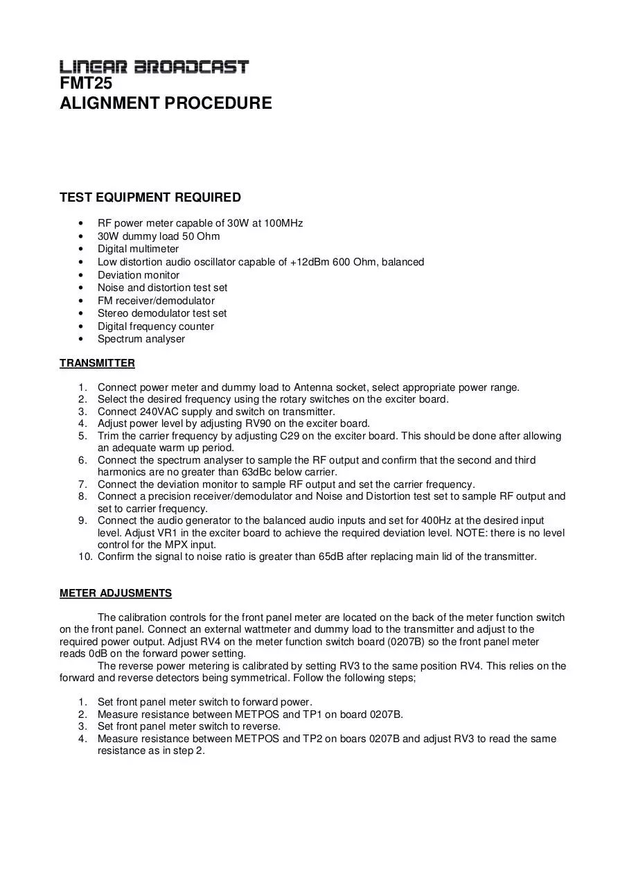
TEST EQUIPMENT REQUIRED
•
•
•
•
•
•
•
•
•
•
RF power meter capable of 30W at 100MHz
30W dummy load 50 Ohm
Digital multimeter
Low distortion audio oscillator capable of +12dBm 600 Ohm, balanced
Deviation monitor
Noise and distortion test set
FM receiver/demodulator
Stereo demodulator test set
Digital frequency counter
Spectrum analyser
TRANSMITTER
1.
2.
3.
4.
5.
6.
7.
8.
9.
10.
Connect power meter and dummy load to Antenna socket, select appropriate power range.
Select the desired frequency using the rotary switches on the exciter board.
Connect 240VAC supply and switch on transmitter.
Adjust power level by adjusting RV90 on the exciter board.
Trim the carrier frequency by adjusting C29 on the exciter board. This should be done after allowing
an adequate warm up period.
Connect the spectrum analyser to sample the RF output and confirm that the second and third
harmonics are no greater than 63dBc below carrier.
Connect the deviation monitor to sample RF output and set the carrier frequency.
Connect a precision receiver/demodulator and Noise and Distortion test set to sample RF output and
set to carrier frequency.
Connect the audio generator to the balanced audio inputs and set for 400Hz at the desired input
level. Adjust VR1 in the exciter board to achieve the required deviation level. NOTE: there is no level
control for the MPX input.
Confirm the signal to noise ratio is greater than 65dB after replacing main lid of the transmitter.
METER ADJUSMENTS
The calibration controls for the front panel meter are located on the back of the meter function switch
on the front panel. Connect an external wattmeter and dummy load to the transmitter and adjust to the
required power output. Adjust RV4 on the meter function switch board (0207B) so the front panel meter
reads 0dB on the forward power setting.
The reverse power metering is calibrated by setting RV3 to the same position RV4. This relies on the
forward and reverse detectors being symmetrical. Follow the following steps;
1.
2.
3.
4.
Set front panel meter switch to forward power.
Measure resistance between METPOS and TP1 on board 0207B.
Set front panel meter switch to reverse.
Measure resistance between METPOS and TP2 on boars 0207B and adjust RV3 to read the same
resistance as in step 2.
Download FMT 25 SERIES HANDBOOK
FMT 25 SERIES HANDBOOK.pdf (PDF, 474.03 KB)
Download PDF
Share this file on social networks
Link to this page
Permanent link
Use the permanent link to the download page to share your document on Facebook, Twitter, LinkedIn, or directly with a contact by e-Mail, Messenger, Whatsapp, Line..
Short link
Use the short link to share your document on Twitter or by text message (SMS)
HTML Code
Copy the following HTML code to share your document on a Website or Blog
QR Code to this page

This file has been shared publicly by a user of PDF Archive.
Document ID: 0000624543.