PROSPER Examination Protocol (PDF)
File information
Author: Priya
This PDF 1.7 document has been generated by Microsoft® Word 2016, and has been sent on pdf-archive.com on 24/07/2017 at 13:38, from IP address 47.29.x.x.
The current document download page has been viewed 455 times.
File size: 683.23 KB (10 pages).
Privacy: public file


File preview
Annexure
Ophthalmic Examination Procedures
Key Points
Inclusion Step 1
• Subject is 40yrs or older
Distance Acuity Test
• Chart at 4m distance, 1m above ground
• Consistent lighting (as possible) across trial period
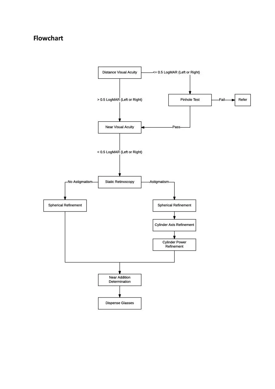
• Pinhole if unaided distance visual acuity is 0.5 LogMAR or worse
Inclusion Step 2
• Unaided Acuity better than 0.5 LogMAR in both eye OR acuity improves through pinhole
Near Acuity Test
• Chart at 40cm distance, at the level of subject’s chin
• Chart held by examiner, subject occludes own eyes using palm of hand
• Maintain 40 cm working distance
Inclusion Step 3
• Unaided near visual acuity is at <= 0.8M on the near chart for either eye
• Subject does not already own or use reading glasses
Distance refraction
• Retinoscopy end-point is neutrality or fastest ‘with’ motion (least myopic correction)
• Trial frame refraction end-point is maximum sphere for best corrected acuity
Inclusion Step 4
• Best corrected distance visual acuity is 0.1 LogMAR or better for both eyes
Near Refraction
• Use a ‘standardized’ tea bush as target
• Let subject determine ‘ideal/desired’ working distance without trial frame and prior to
performing the near refraction
• Measure and record the ‘ideal/desired’ working distance
• Maintain ‘ideal/desired’ working distance throughout testing
• Near refraction end-point is the highest plus sphere value (near-point addition) that enables the
subject to identify 2-3 leaves and a bud that are appropriate for picking at the ‘ideal/desired’
working distance.
Flowchart
Vision Assessment
Distance Visual Acuity
•
•
•
•
•
•
•
•
•
•
•
•
•
•
•
•
•
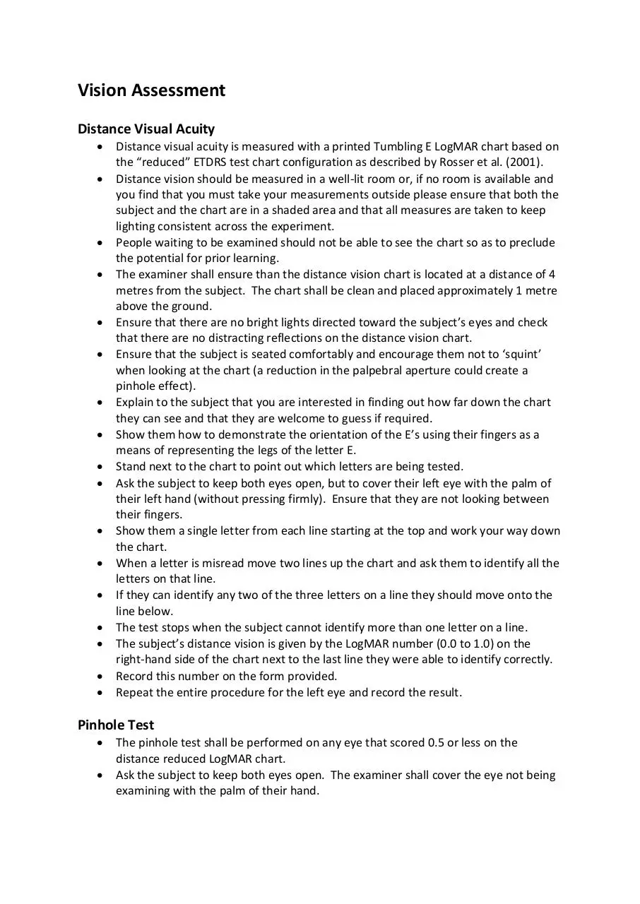
Distance visual acuity is measured with a printed Tumbling E LogMAR chart based on
the “reduced” ETDRS test chart configuration as described by Rosser et al. (2001).
Distance vision should be measured in a well-lit room or, if no room is available and
you find that you must take your measurements outside please ensure that both the
subject and the chart are in a shaded area and that all measures are taken to keep
lighting consistent across the experiment.
People waiting to be examined should not be able to see the chart so as to preclude
the potential for prior learning.
The examiner shall ensure than the distance vision chart is located at a distance of 4
metres from the subject. The chart shall be clean and placed approximately 1 metre
above the ground.
Ensure that there are no bright lights directed toward the subject’s eyes and check
that there are no distracting reflections on the distance vision chart.
Ensure that the subject is seated comfortably and encourage them not to ‘squint’
when looking at the chart (a reduction in the palpebral aperture could create a
pinhole effect).
Explain to the subject that you are interested in finding out how far down the chart
they can see and that they are welcome to guess if required.
Show them how to demonstrate the orientation of the E’s using their fingers as a
means of representing the legs of the letter E.
Stand next to the chart to point out which letters are being tested.
Ask the subject to keep both eyes open, but to cover their left eye with the palm of
their left hand (without pressing firmly). Ensure that they are not looking between
their fingers.
Show them a single letter from each line starting at the top and work your way down
the chart.
When a letter is misread move two lines up the chart and ask them to identify all the
letters on that line.
If they can identify any two of the three letters on a line they should move onto the
line below.
The test stops when the subject cannot identify more than one letter on a line.
The subject’s distance vision is given by the LogMAR number (0.0 to 1.0) on the
right-hand side of the chart next to the last line they were able to identify correctly.
Record this number on the form provided.
Repeat the entire procedure for the left eye and record the result.
Pinhole Test
•
•
The pinhole test shall be performed on any eye that scored 0.5 or less on the
distance reduced LogMAR chart.
Ask the subject to keep both eyes open. The examiner shall cover the eye not being
examining with the palm of their hand.
•
•
•
•
Let the subject hold the Pinhole plate in their hand and encourage them to look
through the hole in the centre of it.
Ask the subject to look at the smallest line of optotypes visible during the distance
visual acuity assessment and ask them to identify the letters on that line.
If their visual acuity improves while viewing the chart through the pinhole plate then
the examiner may continue with the refraction procedures
If the subject’s visual acuity does not improve while looking at the chart through the
pinhole plate then the examiner should refer for further examination
Near Visual Acuity
•
•
•
•
•
•
•
•
•
•
•
•
•
Near visual acuity is measured with a printed Tumbling E LogMAR chart based on the
“reduced” ETDRS test chart configuration as described by Rosser et al. (2001) and
scaled for use at a distance of 40cm.
The examiner shall hold the chart at the level of the subject’s chin and use a ruler to
measure out a distance of 40cm between the chart and the subject. It is essential
that the subject doesn’t move closer or further away from the chart so the examiner
must encourage the subject to remain still.
The examiner must remain vigilant of movement of the chart closer to - or further
away from - the subject to ensure that inaccuracies in the near visual acuity
measurement are not introduced.
Ensure that there are no bright lights directed toward the subject’s eyes and that
there are no distracting reflections on the near vision chart.
Ensure that the subject does not ‘squint’ when looking at the near vision chart (a
reduction in the palpebral aperture could create a pinhole effect).
Ask the subject to keep both eyes open but to cover their left eye with the palm of
their left hand.
Use the back of a pen to show them a single letter from each line starting at the top
and work your way down the chart.
When a letter is misread move two lines up the chart and ask them to identify all the
letters on that line.
If they can identify at least two of the three letters on a line they should move onto
the line below.
The test stops when the subject cannot identify more than one letter on a line.
The subject’s near vision is given by the LogMAR number (0.0 to 1.0) on the righthand side of the chart next to the last line they were able to identify correctly.
Record this number on form provided.
Repeat the entire procedure for the left eye and record the result.
Refraction Procedures
Distance Refraction
1.
2.
Determine starting point using static retinoscopy
Refine retinoscopy result using non-cyclopegic subjective refraction
1. Static Distance Retinoscopy
•
•
•
•
•
•
•
Adjust the height of the examination chair so as to ensure that the subject’s eyes are
at the same level as the examiner’s.
Measure the subject’s interpupillary distance.
Place the trial frame on the subject, ensuring that it is adjusted to the subject’s
interpupillary distance.
The examiner shall seat himself/herself such that his/her head blocks the view of the
distant target for the eye being examined (ensure that the subject can still see the
target with the eye not being examined). This ensures that retinoscopy is performed
as close to the visual axis as possible If the subject finds it difficult to ignore the light
shining into his/her eye the examiner may move off the line of sight of the eye being
examined to facilitate testing.
The retinoscope shall be is held at the examiner’s preferred working distance
(usually either 40cm, 50cm or 67cm). Place the collimating lens (the inverse of the
retinoscopy working distance in metres) in the trial frame and instruct the subject to
keep both eyes open while looking at the target (remind subject that the target may
appear blurred).
Examine the subject’s right eye by moving the beam of the retinoscope across the
eye and observe the motion of the light reflected off the retina through the pupil.
Rotate the retinoscope beam through 360 degrees. If the reflex and the beam
orientation are not continuous throughout the rotation, the eye is astigmatic and the
principle meridians must be identified.
Spherical eyes
• If ‘against’ motion is observed, place minus lenses in front of the eye in
steps of 0.25 D until the motion disappears and neutrality is reached. If
‘with’ motion is observed, place lenses of positive power in front of the eye
in steps of 0.25 D until the motion disappears and neutrality is achieved.
Astigmatic eyes
• Rotate the retinoscope beam through 360 degrees. If the reflex and the
beam orientation are not continuous throughout the rotation, the eye is
astigmatic and the principle meridians must be identified.
• Once the orientation of the principle meridians have been identified, the
examiner shall selects the least myopic (or most hyperopic) meridian to
scope along and neutralizes it through the use or plus or minus spheres.
• The retinoscope beam is then rotated by 90 degrees and the examiner
scopes along the remaining meridian (which should have ‘against
movement’).
• Minus cylinder shall then be placed in the trial frame such that its axis lies
parallel to the orientation of the retinoscope beam (i.e. parallel to the
orientation of the remaining principle meridian).
• Minus cylinder power is added to the trial frame in steps of 0.25 D until
neutrality is reached.
• If neutrality cannot be reached leave the eye with the lowest positive
(most negative) power that is closest to neutrality (i.e smallest ‘with’
movement possible)
• Recheck both principle meridians, ensuring that both are ‘neutral’.
•
•
Repeat the process for the left eye
Remove the collimating lenses and proceed to the subjective refraction
2. Non-cycloplegic Subjective Refraction
Spherical Refinement
• The right eye is tested first and then the left eye. The starting refraction determined
through static distance retinoscopy shall be placed in the trial frame; the left eye is
occluded with an occluder lens and the examiner shall determine the lowest line on
the reduced LogMAR chart for which the subject can read at least 2 of 3 letters.
• With the subject focused on the smallest letters that he/she can read, a +0.50 D
sphere is held in front of the trial frame over the right eye, and the subject is asked if
the lens makes the vision clearer, blurrier, or keeps the vision exactly the same.
(“Clearer, Blurrier, or No change” preferred but “Better, Worse, or No change” can
be used)
• If vision is clearer or there is no change, the sphere in the trial frame is replaced with
a sphere that is 0.50 D more plus or less minus. The subject should be asked to read
the letters through the +0.50 challenge lens to demonstrate that vision is indeed
clearer or the same.
• The +0.50 D sphere is again held in front of the trial frame over the right eye and the
subject is asked again if the lens makes the vision clearer, blurrier, or keeps the
vision exactly the same.
• If vision is again clearer or there is no change, the sphere in the trial frame is
replaced with a sphere that is 0.50 D more plus or less minus.
• This process of increasing the plus sphere or decreasing the minus sphere in the right
eye is repeated until the +0.50 D sphere makes the vision blurrier.
• When the +0.50 D sphere makes the vision blurrier, no additional change in the
sphere is made at this time. By this process the highest plus or least minus sphere for
best vision is determined.
• After determining the highest plus or least minus sphere, the subject is asked to read
the smallest line possible (the reading should be at least as good as the initial
reading). A -0.25 D sphere is held in front of the trial frame before the right eye and
the subject is asked if the lens allows them to read more optotypes.
• If vision is not improved, the +0.50 D sphere is held in front of the trial frame before
the right eye once again to see if the subject will accept more plus.
• If the subject reports that the –0.25 D lens improves vision, the subject is requested
to read the smallest line possible while the –0.25 D lens is held in front of the trial
frame.
• If there is an actual improvement in acuity and the examiner is convinced that the
subject is able to read at least one additional optotype, then the sphere in the trial
frame is replaced by a sphere that is 0.25 D less plus or more minus.
• For each change in spherical power, visual threshold must be determined by asking
the subject to read the smallest line or letters possible either prior to increasing
minus or decreasing plus spherical power (if using a -0.25 D challenge lens) or after
the lens power has been changed.
•
•
•
Minus spherical power is added in –0.25 D increments in this fashion as long as the
subject continues to read at least one additional optotype.
If the subject is unable to read any more optotypes, the sphere is not changed, even
if the subject reports that the vision with the extra minus is better or clearer (or
sharper and darker or more distinct).
The final check in the initial sphere evaluation should be the presentation of a +0.50
D sphere to determine if any more plus sphere will be accepted initially.
Cylinder Axis Refinement
• For purposes of this discussion, only minus cylinder techniques are presented. Plus
cylinders may be used instead of minus cylinders to determine the axis and power of
the cylinder. If plus cylinders are used, the procedure described must be revised to
reflect this change in sign.
• If the starting refraction contains a cylinder correction, changes in cylindrical axis are
tested by holding a 0.50 D Jackson Cross Cylinder in front of the trial frame, first with
the negative axis 45 degrees to one side of the cylinder axis, and then with the
negative axis 45 degrees to the opposite side of the cylinder axis (in most cases, the
handle of the Jackson Cross Cylinder lens should be aligned directly over the axis of
the cylinder lens in the trial frame).
• Instruct the subject to focus on an optotypes two lines above the smallest line on
which he/she can read at least 2 of 3 optotypes.
• Explain to the subject: I am going to show you two views of this “E” and neither view
may be clearer than the view you have right now. I would like to know which of the
two views is the clearer of the two, or are both views about the same or equally
blurry. Ask: Is the “E” clearer on view 1 [flip the lens] or view 2, or are both views
about the same or equally blurred?
• Since neither position may produce a clear image, the subject is encouraged to select
the orientation that offers the least blur.
• If the subject cannot choose between the two orientations of the Jackson Cross
Cylinder at the beginning of this test, the axis of the cylinder is moved 5-15 degrees,
first in one direction and then in the other, with the Jackson Cross Cylinder being
checked in each position to confirm that the original axis was indeed correct.
• If the subject does prefer one position of the cross cylinder to the other, the axis of
the cylinder is moved 5-15 degrees toward the negative axis of the cross cylinder
when in the position the subject said was better.
• When the power of the cylinder is low and/or the subject’s discrimination is poor,
larger shifts will produce more clear-cut responses.
• The cross cylinder is tried again with the negative axis 45 degrees to one side of the
new cylinder axis and then with the negative axis 45 degrees to the opposite side of
the new cylinder axis; the subject is asked which position is the clearer of the two or
if the two views are about the same or equally blurry.
• If the subject prefers one position to the other, the axis of the negative cylinder is
moved toward the negative axis of the cross cylinder.
• Testing for change of axis is repeated until the subject cannot decide that one
position of the cross cylinder is clearer than the other by reporting that both views
are about the same or equally blurry.
Cylinder Power Refinement
• Before refining cylinder power, once again establish visual threshold by determining
the smallest line or letters the subject can read on the chart. Change in cylinder
power is now tested by adding the 0.25 D cross cylinder, first with the negative axis
and then with the positive axis coincident with the cylinder axis.
• Again, instruct the subject to focus on an optotype two lines above the smallest line
for which the subject could correctly identify 2 of 3 optotypes. Explain to the subject:
Once again I am going to show you two views of this “E” and neither view may be
clearer than the view you have right now. I would like to know which of the two
views is the clearer of the two, or are both about the same or equally blurry. Ask: Is
the “E” clearer on view 1 [flip the lens] or view 2, or are both views about the same
or equally blurred?
• If the subject prefers the negative axis coincident with cylinder axis, the power of the
correcting negative cylinder is increased by an additional -0.25 D.
• If the subject prefers the positive axis coincident with the cylinder, the power of the
cylinder is reduced by 0.25 D.
• The process is repeated until the subject cannot choose one of the cross-cylinder
positions as clearer than the other (i.e., until both positions are about the same or
equally blurred).
• Whenever the cylinder is changed by 0.50 D, a 0.25 D of sphere of opposite sign is
added as well (the changing of the sphere occurs during the procedure as soon as
the cylinder has been changed by 0.50 D rather than making the adjustment
following the completion of the refinement).
• If all cylinder power is removed during cylinder power refinement (i.e., sphere only
in the trial frames), check for the presence of astigmatism, following the steps axis
refinement above. In addition, if the cylinder power has been changed by more than
0.50 D, the axis should be refined again.
Checking Cylinder When Beginning Refraction is a Sphere
• If the beginning refraction is a sphere and does not contain a cylinder, the presence
of astigmatism can be tested by one of two methods:
• Instruct the subject to focus on an optotype one-two lines above the smallest line of
optotypes that he/she can read. Using a Jackson Cross Cylinder appropriate for the
current acuity (0.25 D for visual acuity of 0.5 or better; 0.5 D for visual acuity poorer
than 0.5), test for the presence of cylinder power by placing the cross cylinder with
the plus axis alternately at 90 degrees and 180 degrees, and then alternately at 45
degrees and 135 degrees.
• If the subject reports that the Jackson Cross Cylinder makes the optotype clearer
than the spherical correction in any of the four axis locations, insert a cylinder
matching the “minus” presentation of the JCC at the preferred axis and continue the
refraction by refining the cylinder axis and power, as described above.
Refraction Recheck/Final Sphere Refinement
• The power of the sphere is rechecked according to the sphere refinement protocol
above by using +0.25 D and -0.25 D spheres and changing the spherical power by
0.25 D increments of the appropriate sign until the subject reports that the +0.25
lens blurs the vision and the -0.25 does not improve vision. If the sphere is changed
at this point by 0.50 D or more, the cylinder axis and power should be rechecked.
This process is repeated until no further significant lens changes are made.
Near Refraction
•
•
•
Remove the trial frame with the distance refraction from the subject’s face.
Ask the subject to stand near a tea bush (representative of the height of the majority
of tea bushes likely to be worked on over the course of the study) and assume the
stance that they usually use while picking leaves. Instruct them to handle the leaves
on the bush as they would while working.
Ask the subject whether it would be more comfortable to hold their head closer or
further away from the bush while working. Remind them that its ok if the leaves on
Download PROSPER Examination Protocol
PROSPER_Examination Protocol.pdf (PDF, 683.23 KB)
Download PDF
Share this file on social networks
Link to this page
Permanent link
Use the permanent link to the download page to share your document on Facebook, Twitter, LinkedIn, or directly with a contact by e-Mail, Messenger, Whatsapp, Line..
Short link
Use the short link to share your document on Twitter or by text message (SMS)
HTML Code
Copy the following HTML code to share your document on a Website or Blog
QR Code to this page

This file has been shared publicly by a user of PDF Archive.
Document ID: 0000628041.