4123.0000 (PDF)
File information
Title: Microsoft Word - E4123_2012.doc
Author: Schneider
This PDF 1.4 document has been generated by PScript5.dll Version 5.2 / Acrobat Distiller 6.0 (Windows), and has been sent on pdf-archive.com on 21/08/2017 at 09:12, from IP address 72.52.x.x.
The current document download page has been viewed 948 times.
File size: 290.59 KB (6 pages).
Privacy: public file
File preview
4123.0000 BG
Page: 1 / 6
Wind direction sensor
6
5
7
Issue.
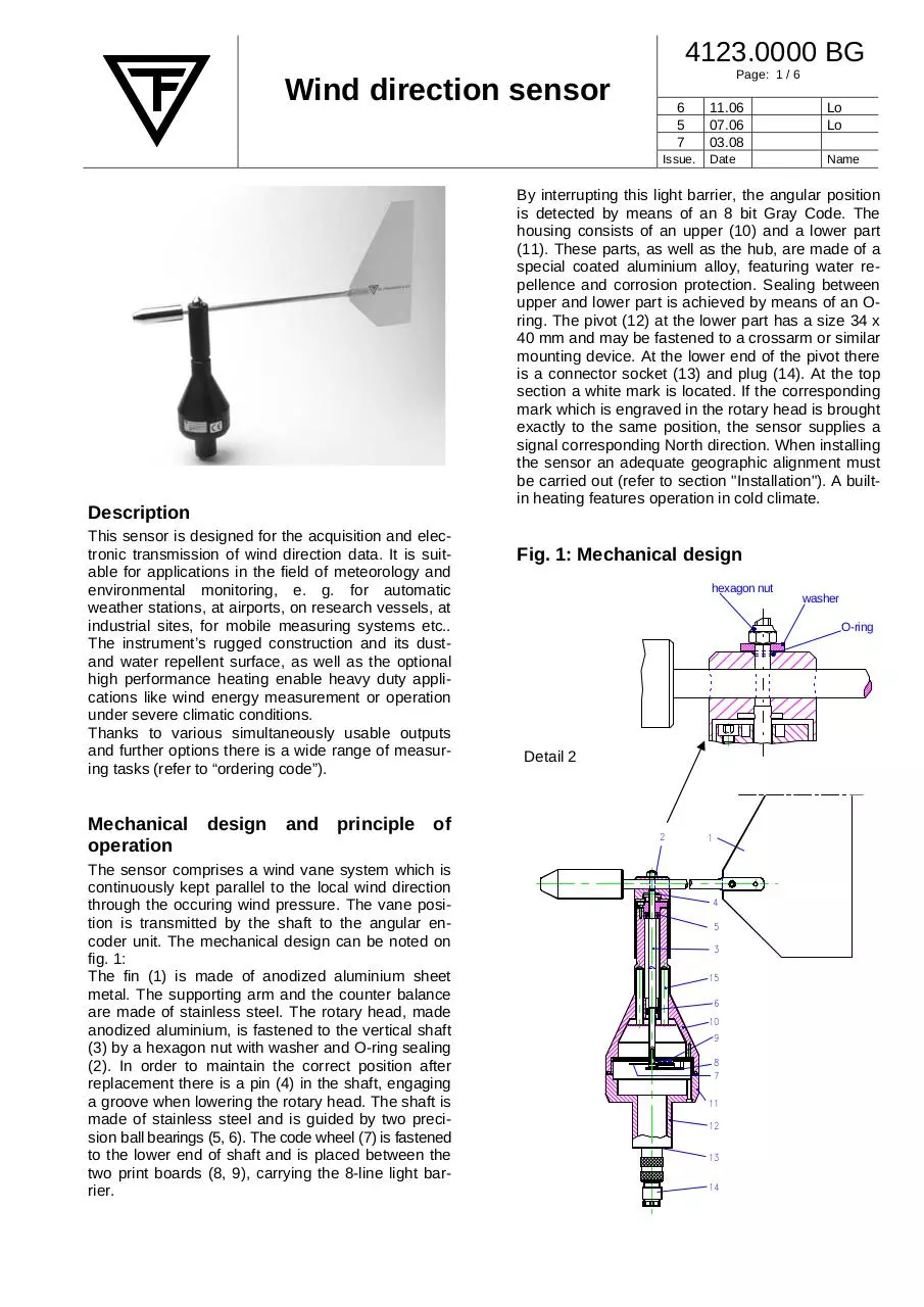
Description
This sensor is designed for the acquisition and electronic transmission of wind direction data. It is suitable for applications in the field of meteorology and
environmental monitoring, e. g. for automatic
weather stations, at airports, on research vessels, at
industrial sites, for mobile measuring systems etc..
The instrument’s rugged construction and its dustand water repellent surface, as well as the optional
high performance heating enable heavy duty applications like wind energy measurement or operation
under severe climatic conditions.
Thanks to various simultaneously usable outputs
and further options there is a wide range of measuring tasks (refer to “ordering code”).
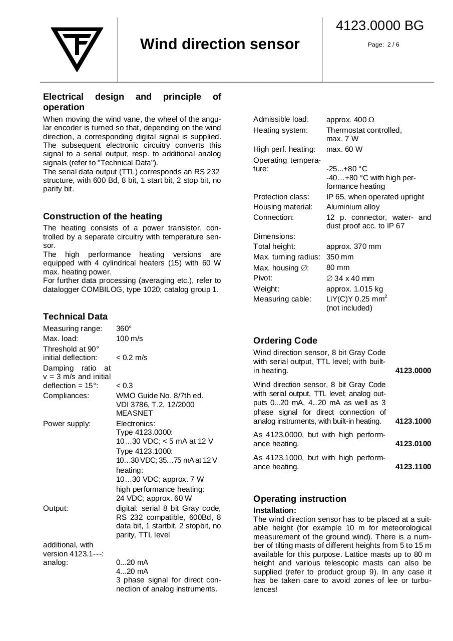
Mechanical design and principle of
operation
The sensor comprises a wind vane system which is
continuously kept parallel to the local wind direction
through the occuring wind pressure. The vane position is transmitted by the shaft to the angular encoder unit. The mechanical design can be noted on
fig. 1:
The fin (1) is made of anodized aluminium sheet
metal. The supporting arm and the counter balance
are made of stainless steel. The rotary head, made
anodized aluminium, is fastened to the vertical shaft
(3) by a hexagon nut with washer and O-ring sealing
(2). In order to maintain the correct position after
replacement there is a pin (4) in the shaft, engaging
a groove when lowering the rotary head. The shaft is
made of stainless steel and is guided by two precision ball bearings (5, 6). The code wheel (7) is fastened
to the lower end of shaft and is placed between the
two print boards (8, 9), carrying the 8-line light barrier.
11.06
07.06
03.08
Lo
Lo
Date
Name
By interrupting this light barrier, the angular position
is detected by means of an 8 bit Gray Code. The
housing consists of an upper (10) and a lower part
(11). These parts, as well as the hub, are made of a
special coated aluminium alloy, featuring water repellence and corrosion protection. Sealing between
upper and lower part is achieved by means of an Oring. The pivot (12) at the lower part has a size 34 x
40 mm and may be fastened to a crossarm or similar
mounting device. At the lower end of the pivot there
is a connector socket (13) and plug (14). At the top
section a white mark is located. If the corresponding
mark which is engraved in the rotary head is brought
exactly to the same position, the sensor supplies a
signal corresponding North direction. When installing
the sensor an adequate geographic alignment must
be carried out (refer to section "Installation"). A builtin heating features operation in cold climate.
Fig. 1: Mechanical design
hexagon nut
washer
O-ring
Detail 2
2
1
4
5
3
15
6
10
9
8
7
11
12
13
14
4123.0000 BG
Wind direction sensor
Electrical
operation
design
and
principle
Page: 2 / 6
of
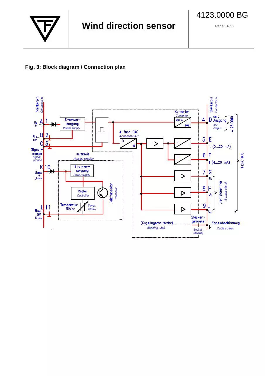
When moving the wind vane, the wheel of the angular encoder is turned so that, depending on the wind
direction, a corresponding digital signal is supplied.
The subsequent electronic circuitry converts this
signal to a serial output, resp. to additional analog
signals (refer to "Technical Data").
The serial data output (TTL) corresponds an RS 232
structure, with 600 Bd, 8 bit, 1 start bit, 2 stop bit, no
parity bit.
Construction of the heating
The heating consists of a power transistor, controlled by a separate circuitry with temperature sensor.
The high performance heating versions are
equipped with 4 cylindrical heaters (15) with 60 W
max. heating power.
For further data processing (averaging etc.), refer to
datalogger COMBILOG, type 1020; catalog group 1.
Admissible load:
Heating system:
approx. 400 Ω
Thermostat controlled,
max. 7 W
max. 60 W
High perf. heating:
Operating temperature:
-25...+80 °C
-40…+80 °C with high performance heating
Protection class:
IP 65, when operated upright
Housing material:
Aluminium alloy
Connection:
12 p. connector, water- and
dust proof acc. to IP 67
Dimensions:
Total height:
approx. 370 mm
Max. turning radius: 350 mm
80 mm
Max. housing ∅:
Pivot:
∅ 34 x 40 mm
Weight:
approx. 1.015 kg
Measuring cable:
LiY(C)Y 0.25 mm2
(not included)
Technical Data
Measuring range:
Max. load:
Threshold at 90°
initial deflection:
Damping ratio at
v = 3 m/s and initial
deflection = 15°:
Compliances:
Power supply:
Output:
additional, with
version 4123.1---:
analog:
360°
100 m/s
< 0.2 m/s
< 0.3
WMO Guide No. 8/7th ed.
VDI 3786, T.2, 12/2000
MEASNET
Electronics:
Type 4123.0000:
10…30 VDC; < 5 mA at 12 V
Type 4123.1000:
10…30 VDC; 35…75 mA at 12 V
heating:
10…30 VDC; approx. 7 W
high performance heating:
24 VDC; approx. 60 W
digital: serial 8 bit Gray code,
RS 232 compatible, 600Bd, 8
data bit, 1 startbit, 2 stopbit, no
parity, TTL level
0...20 mA
4...20 mA
3 phase signal for direct connection of analog instruments.
Ordering Code
Wind direction sensor, 8 bit Gray Code
with serial output, TTL level; with builtin heating.
4123.0000
Wind direction sensor, 8 bit Gray Code
with serial output, TTL level; analog outputs 0...20 mA, 4...20 mA as well as 3
phase signal for direct connection of
analog instruments, with built-in heating.
4123.1000
As 4123.0000, but with high performance heating.
4123.0100
As 4123.1000, but with high performance heating.
4123.1100
Operating instruction
Installation:
The wind direction sensor has to be placed at a suitable height (for example 10 m for meteorological
measurement of the ground wind). There is a number of tilting masts of different heights from 5 to 15 m
available for this purpose. Lattice masts up to 80 m
height and various telescopic masts can also be
supplied (refer to product group 9). In any case it
has be taken care to avoid zones of lee or turbulences!
4123.0000 BG
Wind direction sensor
Page: 3 / 6
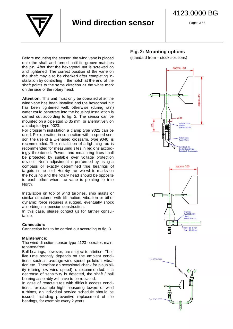
Fig. 2: Mounting options
approx. 350
approx. 370
Attention: This unit must only be operated after the
wind vane has been installed and the hexagonal nut
has been tightened well; otherwise (during rain)
water could penetrate into the housing! Installation is
carried out according to fig. 2. The sensor can be
mounted on a pipe stud ∅ 35 mm, or alternatively on
an adapter type 9023.
For crossarm installation a clamp type 9022 can be
used. For operation in connection with a speed sensor, the use of a U-shaped crossarm, type 9040, is
recommended. The installation of a lightning rod is
recommended for measuring sites in regions accordingly threatened. Power- and measuring lines shall
be protected by suitable over voltage protection
devices! North adjustment is performed by using a
compass or exactly determined true bearings of
targets in the field. Hereby the two white marks on
the housing and the rotary head should be opposite
to each other when the vane is pointing to true
North.
(standard from – stock solutions)
ø 34
105
Before mounting the sensor, the wind vane is placed
onto the shaft and turned until its groove matches
the pin. After that the hexagonal nut is screwed on
and tightened. The correct position of the vane on
the shaft may also be checked after completing installation by controlling if the notch at the end of the
shaft points to the same direction as the white mark
on the side of the rotary head.
Rohr φ48 mm
Tube φ48 mm
Durchbruch für
Steckerdurchführung
Slotted hole for connection
approx. 350
Installation on top of wind turbines, ship masts or
similar structures with tilt motion, vibration or other
dynamic force requires a rugged, eventually shock
absorbing, suspension construction.
In this case, please contact us for further consultance.
Klemmfix
Typ 9022.0000
Clamp
Type 9022.0000
Connection:
Connection has to be carried out according to fig. 3.
Maintenance:
The wind direction sensor type 4123 operates maintenance-free!
Ball bearings, however, are subject to attrition. Their
live time strongly depends on the ambient conditions, such as: average wind speed, pollution, vibration etc.. Therefore an occasional check for plausibility (during low wind speed) is recommended: If a
decrease of sensitivity is detected, the shaft / ball
bearing assembly will have to be replaced.
In case of remote sites with difficult access conditions, for example high measuring towers or wind
turbines, an individual service schedule should be
issued, including preventive replacement of the
bearings, for example every 2 years.
Typ 9023.0000
Adapter
Type 9023.0000
Rohr 33
φ -34 mm
Tube φ33 -34 mm
Typ 9112.2000
Typ 9040.0000
4123.0000 BG
Wind direction sensor
Page: 4 / 6
Connector pi
Connector pi
Fig. 3: Block diagram / Connection plan
Converter
ser.
output
Power supply
4-channel DAC
signal
ground
Heating circuitry
Power supply
Transistor
Controller
3 phase signal
Heat.
Temp.
sensor
Heat.
(Bearing tube)
Socket
housing
Cable screen
4123.0000 BG
Wind direction sensor
Page: 5 / 6
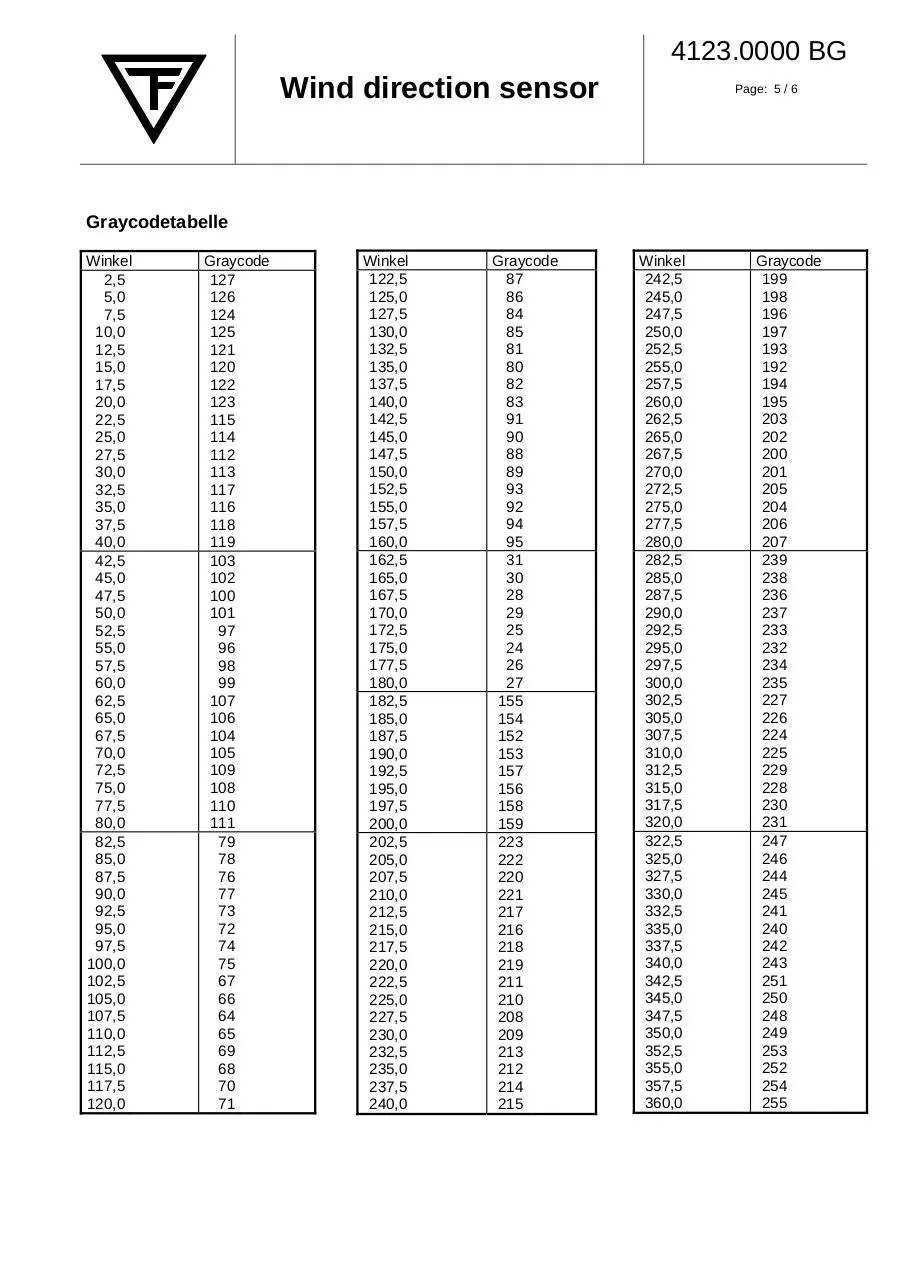
Graycodetabelle
Winkel
2,5
5,0
7,5
10,0
12,5
15,0
17,5
20,0
22,5
25,0
27,5
30,0
32,5
35,0
37,5
40,0
42,5
45,0
47,5
50,0
52,5
55,0
57,5
60,0
62,5
65,0
67,5
70,0
72,5
75,0
77,5
80,0
82,5
85,0
87,5
90,0
92,5
95,0
97,5
100,0
102,5
105,0
107,5
110,0
112,5
115,0
117,5
120,0
Graycode
127
126
124
125
121
120
122
123
115
114
112
113
117
116
118
119
103
102
100
101
97
96
98
99
107
106
104
105
109
108
110
111
79
78
76
77
73
72
74
75
67
66
64
65
69
68
70
71
Winkel
122,5
125,0
127,5
130,0
132,5
135,0
137,5
140,0
142,5
145,0
147,5
150,0
152,5
155,0
157,5
160,0
162,5
165,0
167,5
170,0
172,5
175,0
177,5
180,0
182,5
185,0
187,5
190,0
192,5
195,0
197,5
200,0
202,5
205,0
207,5
210,0
212,5
215,0
217,5
220,0
222,5
225,0
227,5
230,0
232,5
235,0
237,5
240,0
Graycode
87
86
84
85
81
80
82
83
91
90
88
89
93
92
94
95
31
30
28
29
25
24
26
27
155
154
152
153
157
156
158
159
223
222
220
221
217
216
218
219
211
210
208
209
213
212
214
215
Winkel
242,5
245,0
247,5
250,0
252,5
255,0
257,5
260,0
262,5
265,0
267,5
270,0
272,5
275,0
277,5
280,0
282,5
285,0
287,5
290,0
292,5
295,0
297,5
300,0
302,5
305,0
307,5
310,0
312,5
315,0
317,5
320,0
322,5
325,0
327,5
330,0
332,5
335,0
337,5
340,0
342,5
345,0
347,5
350,0
352,5
355,0
357,5
360,0
Graycode
199
198
196
197
193
192
194
195
203
202
200
201
205
204
206
207
239
238
236
237
233
232
234
235
227
226
224
225
229
228
230
231
247
246
244
245
241
240
242
243
251
250
248
249
253
252
254
255
4123.0000 BG
Wind direction sensor
Page: 6 / 6
Montageanleitung, Gegenstecker
Handling instruction, Connector
Section A-A, magnified
Technical data are subject to change!
THEODOR FRIEDRICHS & CO. Meteorologische Geräte und Systeme GmbH
POB 1105 • D 22858 Schenefeld • Tel. (040) 839 600-0 • Fax (040) 839 600-18
Email: info@th-friedrichs.de • http://www.th-friedrichs.de
Download 4123.0000
4123.0000.pdf (PDF, 290.59 KB)
Download PDF
Share this file on social networks
Link to this page
Permanent link
Use the permanent link to the download page to share your document on Facebook, Twitter, LinkedIn, or directly with a contact by e-Mail, Messenger, Whatsapp, Line..
Short link
Use the short link to share your document on Twitter or by text message (SMS)
HTML Code
Copy the following HTML code to share your document on a Website or Blog
QR Code to this page

This file has been shared publicly by a user of PDF Archive.
Document ID: 0000653614.