IDT00610100000000000isro05401 (PDF)
File information
Title: Microsoft Word - GSAT-11 Ground Segment RFP-Final (28th June 2017).docx
Author: isro
This PDF 1.4 document has been generated by PDF24 Creator / GPL Ghostscript 9.07, and has been sent on pdf-archive.com on 15/10/2017 at 17:36, from IP address 27.56.x.x.
The current document download page has been viewed 1008 times.
File size: 932.76 KB (88 pages).
Privacy: public file


File preview
2017
REQUEST FOR PROPOSAL (RFP) FOR
GSAT-11 GROUND SYSTEM
SATCOM SYSTEMS TECHNOLOGY GROUP, SNAA
SPACE APPLICATIONS CENTRE, ISRO
1
DOC: Ka-BAND RFP/GSAT-11 GS/SAC/2017
Request for Proposal (RFP)
Supply, Installation and Commissioning of
GSAT-11 Ground System
SPACE APPLICATIONS CENTRE
INDIAN SPACE RESEARCH ORGANIZATION
AHMEDABAD
2
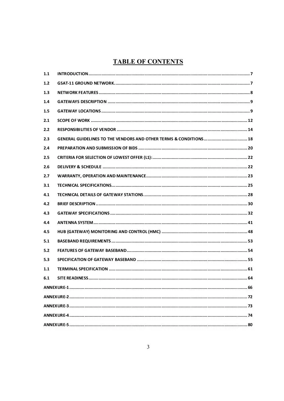
TABLE OF CONTENTS
1.1
INTRODUCTION .............................................................................................................................. 7
1.2
GSAT-11 GROUND NETWORK .......................................................................................................... 7
1.3
NETWORK FEATURES ...................................................................................................................... 8
1.4
GATEWAYS DESCRIPTION ............................................................................................................... 9
1.5
GATEWAY LOCATIONS .................................................................................................................... 9
2.1
SCOPE OF WORK .......................................................................................................................... 12
2.2
RESPONSIBILITIES OF VENDOR ...................................................................................................... 14
2.3
GENERAL GUIDELINES TO THE VENDORS AND OTHER TERMS & CONDITIONS .................................. 18
2.4
PREPARATION AND SUBMISSION OF BIDS ..................................................................................... 20
2.5
CRITERIA FOR SELECTION OF LOWEST OFFER (L1): .......................................................................... 22
2.6
DELIVERY & SCHEDULE ................................................................................................................. 22
2.7
WARRANTY, OPERATION AND MAINTENANCE ............................................................................... 23
3.1
TECHNICAL SPECIFICATIONS .......................................................................................................... 25
4.1
TECHNICAL DETAILS OF GATEWAY STATIONS ................................................................................. 28
4.2
BRIEF DESCRIPTION ...................................................................................................................... 30
4.3
GATEWAY SPECIFICATIONS ........................................................................................................... 32
4.4
ANTENNA SYSTEM ........................................................................................................................ 41
4.5
HUB (GATEWAY) MONITORING AND CONTROL (HMC) ................................................................... 48
5.1
BASEBAND REQUIREMENTS .......................................................................................................... 53
5.2
FEATURES OF GATEWAY BASEBAND .............................................................................................. 54
5.3
SPECIFICATION OF GATEWAY BASEBAND ...................................................................................... 55
1.1
TERMINAL SPECIFICATION ............................................................................................................ 61
6.1
SITE READINESS ............................................................................................................................ 64
ANNEXURE-1 ........................................................................................................................................... 66
ANNEXURE-2 ........................................................................................................................................... 72
ANNEXURE-3 ........................................................................................................................................... 73
ANNEXURE-4 ........................................................................................................................................... 74
ANNEXURE-5 ........................................................................................................................................... 80
3
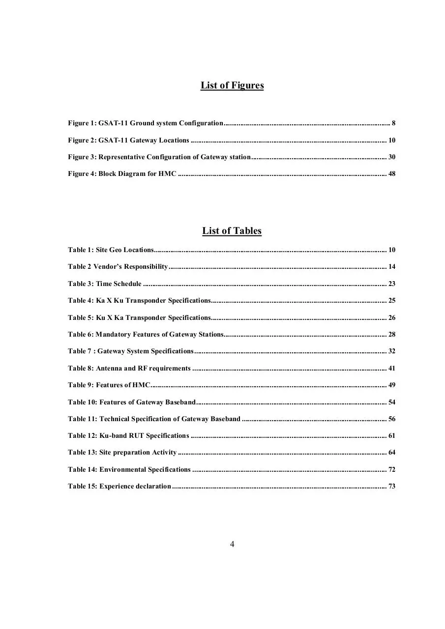
List of Figures
Figure 1: GSAT-11 Ground system Configuration ........................................................................................... 8
Figure 2: GSAT-11 Gateway Locations ........................................................................................................... 10
Figure 3: Representative Configuration of Gateway station .......................................................................... 30
Figure 4: Block Diagram for HMC .................................................................................................................. 48
List of Tables
Table 1: Site Geo Locations............................................................................................................................... 10
Table 2 Vendor’s Responsibility ....................................................................................................................... 14
Table 3: Time Schedule ..................................................................................................................................... 23
Table 4: Ka X Ku Transponder Specifications................................................................................................ 25
Table 5: Ku X Ka Transponder Specifications................................................................................................ 26
Table 6: Mandatory Features of Gateway Stations......................................................................................... 28
Table 7 : Gateway System Specifications ......................................................................................................... 32
Table 8: Antenna and RF requirements .......................................................................................................... 41
Table 9: Features of HMC................................................................................................................................. 49
Table 10: Features of Gateway Baseband ........................................................................................................ 54
Table 11: Technical Specification of Gateway Baseband ............................................................................... 56
Table 12: Ku-band RUT Specifications ........................................................................................................... 61
Table 13: Site preparation Activity .................................................................................................................. 64
Table 14: Environmental Specifications .......................................................................................................... 72
Table 15: Experience declaration ..................................................................................................................... 73
4
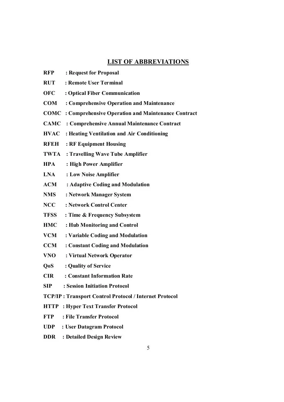
LIST OF ABBREVIATIONS
RFP
: Request for Proposal
RUT
: Remote User Terminal
OFC
: Optical Fiber Communication
COM
: Comprehensive Operation and Maintenance
COMC : Comprehensive Operation and Maintenance Contract
CAMC : Comprehensive Annual Maintenance Contract
HVAC
: Heating Ventilation and Air Conditioning
RFEH
: RF Equipment Housing
TWTA : Travelling Wave Tube Amplifier
HPA
: High Power Amplifier
LNA
: Low Noise Amplifier
ACM
: Adaptive Coding and Modulation
NMS
: Network Manager System
NCC
: Network Control Center
TFSS
: Time & Frequency Subsystem
HMC
: Hub Monitoring and Control
VCM
: Variable Coding and Modulation
CCM
: Constant Coding and Modulation
VNO
: Virtual Network Operator
QoS
: Quality of Service
CIR
: Constant Information Rate
SIP
: Session Initiation Protocol
TCP/IP : Transport Control Protocol / Internet Protocol
HTTP : Hyper Text Transfer Protocol
FTP
: File Transfer Protocol
UDP
: User Datagram Protocol
DDR
: Detailed Design Review
5
Section-1: Introduction to GSAT-11 Ground
Systems
6
1.1 Introduction
Space Applications Centre (SAC) located at Ahmedabad, India is one of the major centers of
the Indian Space Research Organization (1), Department of Space, Government of India.
The next-generation Ku/Ka communication satellite GSAT-11 is currently under development
at ISRO. It is a High Throughput Satellite (HTS) and its application shall primarily focus on
meeting the country-wide demand for satellite based broadband applications.
The ground infrastructure for complete GSAT-11 system will include four (4) Ka-band
Gateways (or Hubs). There will be provisions for multiple service providers to share the
satellite bandwidth at L-band interface in the gateway stations and provide services to the end
users. Each Service provider will have their own network architecture managed by themselves
and operating within the designated bandwidth with their remote terminals. Each Gateway will
have one, diversity site with a capability for seamless switching to counter outages due to rain
fades and provide redundancy. Thus, each of the four Gateways will have one active and one
redundant (space diversity configuration, total 8 RF stations).
The Gateways through their common facilities will provide satellite access to one or more
service providers on Hire-purchase/ Lease / Rent or any other suitable arrangement. The
arrangement of service providers is outside the scope of this document and will be dealt with
separately. However, the Gateways shall be suitably configured and equipped to provide full
set of features and connectivity to multiple service providers.
This “Request for Proposal” is for “Supply, Installation, Commissioning, Operation and
Maintenance of the complete GSAT-11 Ground System Network” comprising all
Gateway Stations and related equipment, defined in this document.
1.2 GSAT-11 Ground Network
GSAT-11 Satellite will provide Ku-band user spot beams, covering Indian mainland as well as
islands regions (Refer Section-3, Technical Details of Satellite Transponders). The Satellite
will also provide Ka-band spot beams for Gateways. Figure-1 shows the overall ground system
comprising four Ka-band Gateway earth stations.
The GSAT-11 Ground network will consist of following major components:
A.
B.
C.
32 Ku-band spot beams over Indian region with frequency and polarization reuse
8 Ka-band spot beams over Indian region with frequency and polarization reuse
Four interconnected Ka-band Gateways (Main Gateways) using OFC link. each
main Gateway will have one diversity site with RF systems.
7
D.
The Diversity Gateway will be located at a distance of minimum 10 Km from Main
Gateway and connected through OFC link.
E. Ku-band 1.2m VSATs (Remote User Terminals-RUTs)
GSAT-11
Ku-Band
Ku-Band Terminals
Ka Band
South
Beam
Ka Band
North
Beam
Hub Main &
Redundant
(North Beam)
Hub Main &
Redundant
(East Beam)
Hub
HubMain
Main&&
Redundant
Redundant
(South
(West
Beam)
beam)
Hub Main &
Redundant
(South Beam)
OFC Link
Terrestrial
Network
Figure 1: GSAT-11 Ground system
1.3
Network features
1.
2.
3.
4.
5.
Configuration
The Gateways will communicate to Satellite in Ka-band
RUTs will communicate in Ku-band with Satellite.
Star connectivity between Ku-band RUTs through Ka-band Gateways. The user-touser communication will only be possible via Gateways.
Each Gateway will be connected to the RUTs through eight Ku-band spot beams in
both polarizations (four beams in one polarization, total eight beams)
All Gateways shall be interconnected through OFC ground network for enabling
seamless flow of user data for all India coverage.
8
1.4
Gateways Description
1. Each Gateway will house number of service providers, who will be allotted satellite
bandwidth capacity with access at IF level (L-Band).
2. Each Gateway station will be connected to corresponding diversity stations at L-band.
3. While only RF sub-system will be installed at diversity site, Base band sub-systems
will be housed at main Gateway stations.
4. The main Gateways will be the master and should take care of seamless switchover
process and delay compensation associated with RF switchover to diversity sites in case
of rain fade.
5. The RF systems will have to provide L-band interface to connect multiple (up to 10)
baseband equipment housed at Main Gateway stations for establishment of
communication network. L band interface connector details (i.e. SMA, N type) will be
finalized during DDR. All four Main Gateways will be inter-connected to one-another
through OFC links for Pan-India coverage among user nodes.
6. It should be possible to operate the Gateways independently or from a common control
site, which may or may not be co-located with any of the Gateways.
7. With respect to baseband, it is planned to establish baseband equipment in each
Gateway. The baseband equipment for this portion is part of this RFP.
1.5 Gateway Locations
The Gateways shall be installed at different locations in India. These locations are Ahmedabad,
Delhi, Ranchi, and Bangalore. However, the exact location of the site within the places
mentioned will be decided at the time of DDR,
Figure- 2 provides a country-wide map of India, showing site locations. Table-1 provides
Gateway Geo Location of the sites:
9
Download IDT00610100000000000isro05401
IDT00610100000000000isro05401.pdf (PDF, 932.76 KB)
Download PDF
Share this file on social networks
Link to this page
Permanent link
Use the permanent link to the download page to share your document on Facebook, Twitter, LinkedIn, or directly with a contact by e-Mail, Messenger, Whatsapp, Line..
Short link
Use the short link to share your document on Twitter or by text message (SMS)
HTML Code
Copy the following HTML code to share your document on a Website or Blog
QR Code to this page

This file has been shared publicly by a user of PDF Archive.
Document ID: 0000685556.