3D printing (PDF)
File information
Author: 123
This PDF 1.5 document has been generated by Microsoft® Word 2013, and has been sent on pdf-archive.com on 17/10/2017 at 09:30, from IP address 37.255.x.x.
The current document download page has been viewed 324 times.
File size: 417.06 KB (29 pages).
Privacy: public file


File preview
3D
printing
Researcher Pr. Reza Azimi
3D Printing, also known as Additive Manufacturing (AM),
refers to processes used to create a threedimensional object[1] in which layers of material are formed
under computer control to create an object.[2] Objects can be
of almost any shape or geometry and typically are produced
using digital model data from a 3D model or another
electronic data source such as an Additive Manufacturing
File (AMF) file. STereoLithography (STL) is one of the most
common file types that 3D printers can read. Thus, unlike
material removed from a stock in the conventional
machining process, 3D printing or AM builds a threedimensional object from computer-aided design (CAD)
model or AMF file by successively adding material layer by
layer.[3]
The term "3D printing" originally referred to a process that
deposits a binder material onto a powder bed with inkjet
printer heads layer by layer. More recently, the term is
being used in popular vernacular to encompass a wider
variety of additive manufacturing techniques. United States
and global technical standards use the official term additive
manufacturing for this broader sense.
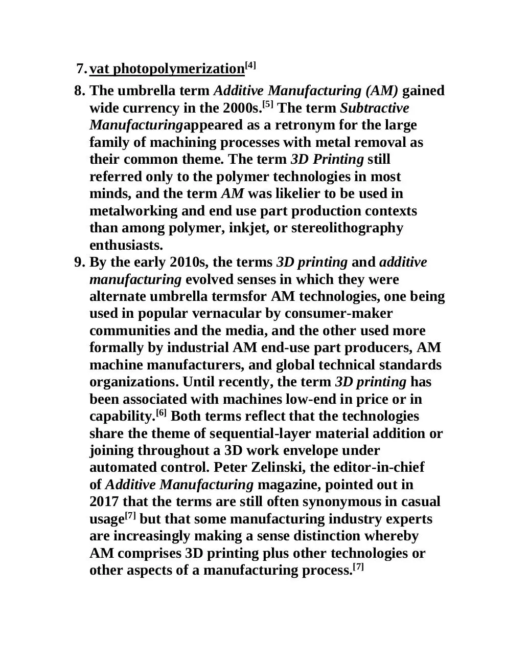
ISO/ASTM52900-15 defines seven categories of Additive
Manufacturing (AM) processes within its meaning:
1. binder jetting
2. directed energy deposition
3. material extrusion
4. material jetting
5. powder bed fusion
6. sheet lamination
7. vat photopolymerization[4]
8. The umbrella term Additive Manufacturing (AM) gained
wide currency in the 2000s.[5] The term Subtractive
Manufacturingappeared as a retronym for the large
family of machining processes with metal removal as
their common theme. The term 3D Printing still
referred only to the polymer technologies in most
minds, and the term AM was likelier to be used in
metalworking and end use part production contexts
than among polymer, inkjet, or stereolithography
enthusiasts.
9. By the early 2010s, the terms 3D printing and additive
manufacturing evolved senses in which they were
alternate umbrella termsfor AM technologies, one being
used in popular vernacular by consumer-maker
communities and the media, and the other used more
formally by industrial AM end-use part producers, AM
machine manufacturers, and global technical standards
organizations. Until recently, the term 3D printing has
been associated with machines low-end in price or in
capability.[6] Both terms reflect that the technologies
share the theme of sequential-layer material addition or
joining throughout a 3D work envelope under
automated control. Peter Zelinski, the editor-in-chief
of Additive Manufacturing magazine, pointed out in
2017 that the terms are still often synonymous in casual
usage[7] but that some manufacturing industry experts
are increasingly making a sense distinction whereby
AM comprises 3D printing plus other technologies or
other aspects of a manufacturing process.[7]
10.
Other terms that have been used as AM synonyms
or hypernyms have included desktop
manufacturing, rapid manufacturing (as the logical
production-level successor to rapid prototyping), and ondemand manufacturing (which echoes on-demand
printing in the 2D sense of printing). That such
application of the adjectives rapid and on-demand to the
noun manufacturing was novel in the 2000s reveals the
prevailing mental model of the long industrial era in
which almost all production manufacturing involved
long lead timesfor laborious tooling development.
Today, the term subtractive has not replaced the
term machining, instead complementing it when a term
that covers any removal method is needed. Agile
tooling is the use of modular means to design tooling
that is produced by additive manufacturing or 3D
printing methods, to enable quick prototyping and
responses to tooling and fixture needs. Agile tooling uses
a cost effective and high quality method to quickly
respond to customer and market needs, and it can be
used in hydro-forming, stamping, injection molding and
other manufacturing processes.
Early additive manufacturing equipment and materials were
developed in the 1980s.[8] In 1981, Hideo
Kodama of Nagoya Municipal Industrial Research Institute
invented two additive methods for fabricating threedimensional plastic models with photo-hardening thermoset
polymer, where the UV exposure area is controlled by a
mask pattern or a scanning fiber transmitter.[9][10]
On July 16, 1984 Alain Le Méhauté, Olivier de Witte,
and Jean Claude André filed their patent for
the stereolithography process.[11] The application of the
French inventors was abandoned by the French General
Electric Company (now Alcatel-Alsthom) and CILAS (The
Laser Consortium).[12] The claimed reason was "for lack of
business perspective".[13]
Three weeks later in 1984, Chuck Hull of 3D
Systems Corporation[14] filed his own patent for
a stereolithography fabrication system, in which layers are
added by curing photopolymers with ultraviolet light lasers.
Hull defined the process as a "system for generating threedimensional objects by creating a cross-sectional pattern of
the object to be formed,".[15][16] Hull's contribution was
the STL (Stereolithography) file format and the digital
slicing and infill strategies common to many processes today.
The technology used by most 3D printers to date—especially
hobbyist and consumer-oriented models—is fused deposition
modeling, a special application of plastic extrusion,
developed in 1988 by S. Scott Crump and commercialized by
his company Stratasys, which marketed its first FDM
machine in 1992.
The term 3D printing originally referred to a powder bed
process employing standard and custom inkjet print heads,
developed at MIT in 1993 and commercialized by Soligen
Technologies, Extrude Hone Corporation, and Z
Corporation.
The year 1993 also saw the start of a company
called Solidscape, introducing a high-precision polymer jet
fabrication system with soluble support structures,
(categorized as a "dot-on-dot" technique).
AM processes for metal sintering or melting (such
as selective laser sintering, direct metal laser sintering,
and selective laser melting) usually went by their own
individual names in the 1980s and 1990s. At the time, all
metalworking was done by processes that we now call nonadditive (casting, fabrication, stamping, and machining);
although plenty of automation was applied to those
technologies (such as by robot welding and CNC), the idea of
a tool or head moving through a 3D work envelope
transforming a mass of raw material into a desired shape
layer by layer was associated in metalworking only with
processes that removed metal (rather than adding it), such
as CNC milling, CNC EDM, and many others. But the
automated techniques that added metal, which would later
be called additive manufacturing, were beginning to
challenge that assumption. By the mid-1990s, new
techniques for material deposition were developed
at Stanford and Carnegie Mellon University, including
microcasting[17] and sprayed materials.[18] Sacrificial and
support materials had also become more common, enabling
new object geometries.[19]
As the various additive processes matured, it became clear
that soon metal removal would no longer be the
only metalworking process done through a tool or head
moving through a 3D work envelope transforming a mass of
raw material into a desired shape layer by layer. The 2010s
were the first decade in which metal end use parts such as
engine brackets[20] and large nuts[21] would be grown (either
before or instead of machining) in job production rather
than obligately being machined from bar stock or plate. It is
still the case that casting, fabrication, stamping, and
machining are more prevalent than AM in metalworking,
but AM is now beginning to make significant inroads, and
with the advantages of design for additive manufacturing, it
is clear to engineers that much more is to come.
As technology matured, several authors had begun to
speculate that 3D printing could aid in sustainable
development in the developing world. 3D printing was
perceived to be the future of 2D printing.[22][23][24]
3D printable models may be created with a computer-aided
design (CAD) package, via a 3D scanner, or by a
plain digital camera and photogrammetry software. 3D
printed models created with CAD result in reduced errors
and can be corrected before printing, allowing verification in
the design of the object before it is printed.[25]
CAD model used for 3D printing
The manual modeling process of preparing geometric data
for 3D computer graphics is similar to plastic arts such as
sculpting. 3D scanning is a process of collecting digital data
on the shape and appearance of a real object, creating a
digital model based on it.
Printing[edit]
Timelapse video of a hyperboloid object (designed by George
W. Hart) made of PLA using a RepRap "Prusa Mendel" 3D
printer for molten polymer deposition
Before printing a 3D model from an STL file, it must first be
examined for errors. Most CAD applications produce errors
in output STL files:[26][27]
1. holes.
2. faces normals.
3. self-intersections.
4. noise shells.
5. manifold errors.[28]
A step in the STL generation known as "repair" fixes such
problems in the original model.[29][30] Generally STLs that
have been produced from a model obtained through 3D
scanning often have more of these errors.[31] This is due to
how 3D scanning works-as it is often by point to point
acquisition, reconstruction will include errors in most
cases.[32]
Once completed, the STL file needs to be processed by a
piece of software called a "slicer," which converts the model
into a series of thin layers and produces a G-code file
containing instructions tailored to a specific type of 3D
printer (FDM printers).[citation needed] This G-code file can then
be printed with 3D printing client software (which loads the
G-code, and uses it to instruct the 3D printer during the 3D
printing process).
Printer resolution describes layer thickness and X-Y
resolution in dots per inch (dpi) or micrometers (µm).
Typical layer thickness is around 100 µm (250 DPI),
although some machines can print layers as thin as 16 µm
(1,600 DPI).[33] X-Y resolution is comparable to that of laser
printers. The particles (3D dots) are around 50 to 100 µm
(510 to 250 DPI) in diameter.[citation needed]
Construction of a model with contemporary methods can
take anywhere from several hours to several days,
depending on the method used and the size and complexity
of the model. Additive systems can typically reduce this time
to a few hours, although it varies widely depending on the
type of machine used and the size and number of models
being produced simultaneously.[34]
Traditional techniques like injection moulding can be less
expensive for manufacturing polymer products in high
quantities, but additive manufacturing can be faster, more
flexible and less expensive when producing relatively small
quantities of parts. 3D printers give designers and concept
development teams the ability to produce parts and concept
models using a desktop size printer.[35]
Seemingly paradoxic, more complex objects can be cheaper
for 3D printing production than less complex objects.[citation
needed]
Download 3D printing
3D printing.pdf (PDF, 417.06 KB)
Download PDF
Share this file on social networks
Link to this page
Permanent link
Use the permanent link to the download page to share your document on Facebook, Twitter, LinkedIn, or directly with a contact by e-Mail, Messenger, Whatsapp, Line..
Short link
Use the short link to share your document on Twitter or by text message (SMS)
HTML Code
Copy the following HTML code to share your document on a Website or Blog
QR Code to this page

This file has been shared publicly by a user of PDF Archive.
Document ID: 0000686566.