Laser Harp Online Instructions 5 (PDF)


File preview
Laser Harp Build Instructions
This is a simplified version of the Laser Harp project built by the Artisan’s Asylum hackerspace in
Somerville, Massachusetts, and winners of the RadioShack East Vs. West Hackerspace Challenge.
The Artisan’s Asylum version of the harp is quite large and involved a considerable amount of
construction. It has 12 strings, uses an Arduino Mega and communicates with a PC, which plays the
audio samples. Plucking the strings also triggers cool lighting effects.
This version has been scaled down a bit to make it a great beginner project, but the basic functionality
is the same: a set of laser pointers are aimed at a series of photoresistors, which are hooked up to the
input pins on an Arduino. The Arduino is running a program that detects any interruptions in the beams
and plays the note corresponding to that sensor. The harp is played by “plucking” the laser strings; i.e.,
blocking the path of the laser.
For this version, the Arduino itself produces the audio, and a small piezo speaker is connected directly
to the Arduino. These instructions describe how to build a three-string harp, which allows us to use the
smaller Arduino Uno. Adding more strings is easy: the Uno can handle up to five sensors; more than
that will require an Arduino with more input pins, such as the Mega.
Parts
Note: the parts for this simplified version of the project are different than what appears in print in the
magazine, which lists the parts used in the full-size version.
Arduino Uno:
http://www.radioshack.com/product/index.jsp?productId=12268262
Laser pointer device, e.g.:
http://www.radioshack.com/product/index.jsp?productId=4344500
or:
http://www.radioshack.com/product/index.jsp?productId=2103037
3 photoresistors:
http://www.radioshack.com/product/index.jsp?productId=2062590
3 10k resistors
http://www.radioshack.com/product/index.jsp?productId=2062347
Piezo speaker:
http://www.radioshack.com/product/index.jsp?productId=2062402
Potentiometer:
http://www.radioshack.com/product/index.jsp?productId=2062354&filterName=Type&filterV
alue=Potentiometers
Solid-core hookup wire:
http://www.radioshack.com/product/index.jsp?productId=2049743
Solderless breadboard:
http://www.radioshack.com/product/index.jsp?productId=2882885
Jumper wire kit:
http://www.radioshack.com/product/index.jsp?productId=2103801
Getting Started
Install Arduino Software
Download Arduino software from the Arduino website: http://arduino.cc
If you’ve not used an Arduino before, you’ll want to spend some time familiarizing yourself with the
basics. Check out the Arduino website (above) for some great beginner tutorials.
Install the Tone Library
For this project, you’ll need to install the “Tone” library, which can be downloaded here:
http://code.google.com/p/rogue-code/wiki/ToneLibraryDocumentation
When you unzip the downloaded file, it will create a “Tone” folder. This folder should be moved to the
“Libraries” folder, which is in your Arduino sketchbook folder. If you’re not sure of your sketchbook
folder location, it can be found in your Arduino preferences. If the “libraries” folder doesn’t exist, create
it, then copy the “Tone” folder to that location. Restart your Arduino application. You should now see
“Tone” when you select from the menu bar:
Sketch > Import Library... (look under “Contributed”)
For more information, see “Contributed Libraries” on the page: http://arduino.cc/it/Reference/Libraries
How it Works
Photo Sensors
The laser-detecting circuits use a photoresistor paired with a resistor to create a voltage divider. A
change in resistance in one of the resistors creates a change in voltage. The photoresistor’s resistance
changes according to the intensity of the light hitting it; the brighter the light, the lower the resistance.
Each sensor circuit is hooked up to an analog input pin. The pin reads variations in voltage and
translates them to a value from 0 to 1023, which can be read by the Arduino program (or sketch)
running on the device. Depending on the value, the sketch will determine if the laser is hitting the
sensor.
Calibration
Because the photoresistors will behave differently depending on various ambient lighting conditions,
we need a way to calibrate the sensors. We’ll calibrate manually using a potentiometer as an input.
The potentiometer also acts as a voltage divider and will be hooked up to one of the analog input pins.
Turning the potentiometer sends a value from 0 to 1023 to your Arduino sketch. This will be used to
dial in the calibration (more on this later).
The Sketch
Download the “LaserHarpJr” sketch from here:
http://www.radioshack.com/graphics/uc/rsk/Support/ProductManuals/RS_DIY_LaserHarpJr.ino.zip
Unzip it and open the “LaserHarpJr.ino” file with your Arduino software. You don’t need to understand
everything about the sketch to build this project, but familiarizing yourself with it is a great way to learn
about programming an Arduino. It’s also a good starting point for customization. For example, if you
want to add more sensors or change the notes played by the harp, find the following chunk of code,
which defines the analog input pin and the musical note for each sensor:
sensor[0].pin = A0;
sensor[0].note = NOTE_G3;
sensor[1].pin = A1;
sensor[1].note = NOTE_D4;
sensor[2].pin = A2;
sensor[2].note = NOTE_A4;
If you want to change the sequence of notes from this arpeggio to the first three notes of the C-major
scale, simply change “NOTE_G3” to “NOTE_C4” and “NOTE_A4” to “NOTE_E4”. Note that if you want
to add “strings,” you’ll need to change the following line as well, towards the top of the sketch:
const int SENSOR_COUNT = 3;
More information about the tone library can be found here:
http://code.google.com/p/rogue-code/wiki/ToneLibraryDocumentation
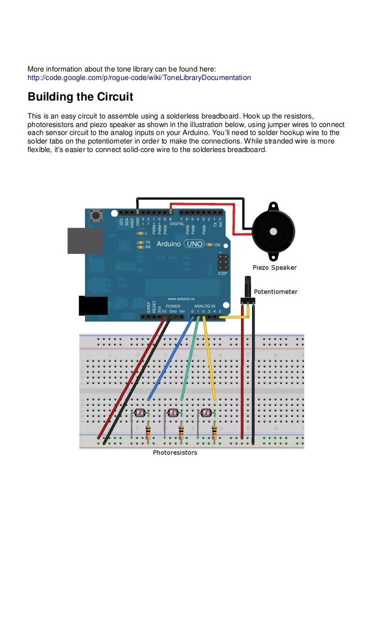
Building the Circuit
This is an easy circuit to assemble using a solderless breadboard. Hook up the resistors,
photoresistors and piezo speaker as shown in the illustration below, using jumper wires to connect
each sensor circuit to the analog inputs on your Arduino. You’ll need to solder hookup wire to the
solder tabs on the potentiometer in order to make the connections. While stranded wire is more
flexible, it’s easier to connect solid-core wire to the solderless breadboard.
When
assembled, it
should look
something like
this.
No need to worry
about setting up
the lasers just
yet!
Program
ming the
Arduino
Next we’ll upload
the Arduino
sketch to the
device. Connect
your Arduino to
your computer
using a USB A/B cable, and make sure the right board and serial port are selected (see the
appropriate “Getting Started” section for your operating system:
http://arduino.cc/en/Guide/HomePage).
Open the “LaserHarpJr.ino” file with your Arduino software and click the right-arrow button (next to the
check button). Some LEDs should blink on the Arduino board, and after a few moments, you should
see “Done Uploading” in the console area of the Arduino software. Your sketch should now be running!
Testing Without a Laser
Using only the ambient light in the room, we can test the harp's sensors before setting up the lasers.
However, the sensors will need to be calibrated first.
Calibration
You may or may not hear a tone coming from the speaker; slowly turning the potentiometer should
cause the tone to turn on (or off) at some point. The trick is to turn
it just past the point where the tone turns off; at this point, any reduction in light falling on the sensor
should trigger it, causing the tone for that sensor to sound.
Test
When you’re done calibrating, test each sensor (one at a time) by putting a finger over it:
When a sensor is blocked, you should hear a tone. When you remove your finger, the tone should
stop. Move your finger from sensor to sensor. You should hear a series of notes (a different note for
each sensor).
Troubleshooting
If it’s not working...
• Check all connections. Make sure all components and jumper wires are in the appropriate rows in the
solderless breadboard. Make sure you’ve connected to the correct pins on the Arduino.
• Use a multimeter to test your circuit. Hook it up in voltage testing mode to test the voltage coming
from each photoresistor (In the illustration and photo above, you would test the blue, green and yellow
wires coming from each sensor. Unplug each wire in turn from the Arduino and test the voltage across
the wire and ground. The voltage should vary as you block and unblock the sensor).
• Use a multimeter to test the resistance of the photoresistors. A fully blocked photoresistor should be
in the same ballpark as the fixed (non-photo) resistor in the
voltage divider circuit. If the resistance is significantly different (e.g., 10K vs. 100K), try to find a
photoresistor in the correct range. Otherwise, replace the fixed resistor with one of a similar value as
the blocked photoresistor.
If you want to see what’s going on in the Arduino program, turn on debug input in the sketch by
changing this line:
const boolean DEBUG = false;
To this:
const boolean DEBUG = true;
Turn on the Serial Monitor in Arduino while the program is running, keeping the USB cable connected.
This will print some interesting information to the screen as you play your harp, but it will negatively
affect its performance; there will be a lag as you block and unblock the beams.
Laser Time!
Once you have everything working, it’s time to set up the lasers. (You might want to power down the
Arduino for now by unplugging its USB cable.)
There is any number of ways to position the lasers, as long as each beam points at one of the sensors.
I happened to have a microphone boom stand kicking around, so I used that as a horizontal bar onto
which I clamped the three laser pointers, using three small spring clamps and some gaffer’s tape:
However, the
endless! For example,
position the pointers
staircase so that
melodies play when
and down the stairs!
require some additional
course).
possibilities are
you could
along a
different
people walk up
(This will
wiring, of
In any case, the lasers must be aimed carefully so that they hit each photoresistor,
and you will need to re-calibrate. Power on the Arduino by plugging in the USB cable (you can also use
a 9V battery, plugged in using a barrel connector). With all three lasers hitting the sensors, turn the
potentiometer just past the point where you stop hearing a tone.
Play Your Harp
Place your hand in the path of one of the three lasers. You should hear a note play. When you move it
out of the path, the note should stop. As you move your hand from beam to beam, you should hear a
series of notes, with each laser “string” playing a different note.
Download Laser Harp Online Instructions-5
Laser_Harp_Online_Instructions-5.pdf (PDF, 1.37 MB)
Download PDF
Share this file on social networks
Link to this page
Permanent link
Use the permanent link to the download page to share your document on Facebook, Twitter, LinkedIn, or directly with a contact by e-Mail, Messenger, Whatsapp, Line..
Short link
Use the short link to share your document on Twitter or by text message (SMS)
HTML Code
Copy the following HTML code to share your document on a Website or Blog
QR Code to this page

This file has been shared publicly by a user of PDF Archive.
Document ID: 0000697281.